Call us 24/7uaedcs@163.com
Welcome to the official website of CNIACS Automation Technology Co., Ltd!
Call us 24/7uaedcs@163.com

WOODWARD PG-PL Governor Installation and Operation

Basic information of the document

Document type: PG-PL Governor Installation and Operation Manual

Manual Number: 36694 (Revision P)

Applicable product: Woodward PG-PL governor (used for speed control of engines, turbines, and other prime movers)

Core safety requirements

(1) Warning definition and protection principles

Danger (DANGER): Failure to avoid causing death or serious injury

Warning: Failure to avoid may result in death or serious injury

CAUTION: Failure to avoid may result in minor or moderate injury

Notice: May only cause property damage

Important: Operation tips or maintenance recommendations

(2) Key safety measures

The prime mover must be equipped with an overspeed shutdown device independent of the speed control system, and if necessary, an overtemperature/overpressure shutdown device must be installed

Wear appropriate PPE during operation, including goggles, hearing protection equipment, helmets, gloves, safety boots, respirators, etc

Be prepared for emergency shutdown when starting the prime mover to prevent loss of control or overspeed

Electrostatic protection: Release human static electricity before coming into contact with electronic controls, avoid using non anti-static plastic/vinyl materials, and do not touch printed circuit board components

(3) Special scenario security

Automotive application: A monitoring device independent of the speed control system needs to be installed (if Woodward control is a monitoring control)

Battery charging device: Before disconnecting the battery, the charging device must be turned off

Solvent usage: Operate in a well ventilated area, away from sources of ignition, and follow the manufacturer’s instructions

Installation and commissioning specifications

(1) Installation requirements

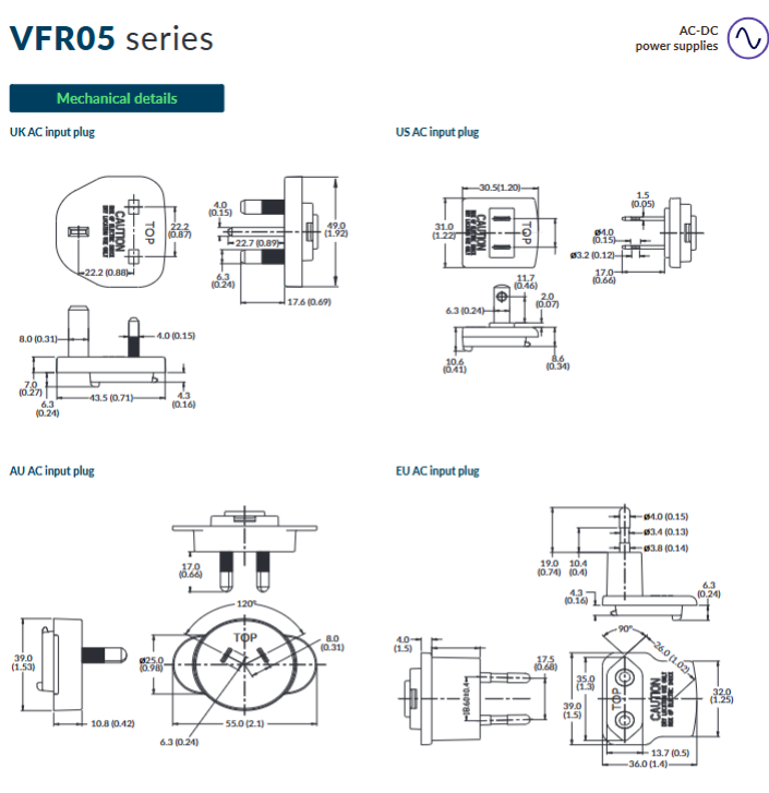
Please refer to Figure 5-3 to confirm the physical dimensions and reserve gaps for installation, disassembly, and maintenance

A gasket needs to be added between the installation surface and the governor base to ensure that the installation is square and the transmission connection is aligned

The transmission gear needs to have no jamming or excessive backlash to avoid affecting the stability of speed regulation

(2) Oil specifications and requirements

Specific project parameters

Oil type: Hydraulic lubricating oil (compatible with nitrile, polyacrylic acid, fluorocarbon sealing materials)

Viscosity range: 50-3000 SUS at operating temperature, ideal 100-300 SUS

Applicable standard API “5” group or “C” group (SA-SF, CA-CD), MIL-L-2104A, etc

Temperature requirement: Continuous working oil temperature of 60-93 ℃, ambient temperature of -29-93 ℃

The oil capacity is 29 ft lb (39 J) and the rotary servo governor is 1.6 US quarts (1.5 liters)

The replacement requirement is to replace the oil immediately when it deteriorates/becomes contaminated, and the ideal working condition can be extended to more than 6 months

(3) Key adjustment operations

Connecting rod adjustment: Ensure that the fuel/steam valve is just closed when the power piston of the governor reaches the end of its stroke in the “closing” direction; Fully open fuel control before maximum travel

Start speed setting: set the direct acting governor to the minimum speed, and the reverse acting governor to the maximum speed (set to the minimum when the air pressure signal is unknown)

Compensation needle valve adjustment: Open the needle valve at idle until the engine fluctuates, then gradually close it until the fluctuation is eliminated, and keep it open for 1/16-2 turns

High and low speed adjustment: By setting the speed control nut, limit screw, etc., ensure that the minimum control air pressure corresponds to the minimum speed, and the maximum control air pressure corresponds to the maximum speed (direct speed control)

Working principle

(1) Core functions

Implement isochronous control: Within the capacity range of the prime mover, maintain a stable speed regardless of load changes

Control logic: By adjusting the fuel or steam supply, respond to changes in engine speed

(2) Key components and mechanisms

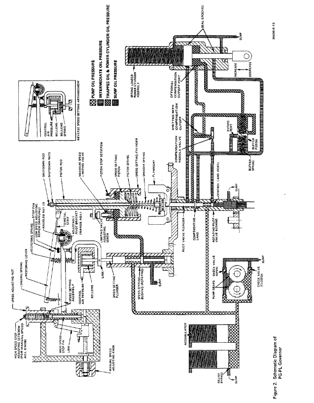
Core components: oil pump, pressure storage area, relief valve, flyweight head directional valve assembly, power cylinder, compensation system, pneumatic speed control mechanism

Speed regulation mechanism

Direct speed regulation: control the increase of air pressure → increase of speed (minimum 3 psi, maximum 100 psi)

Reverse speed regulation: control the increase of air pressure → decrease of speed

Manual speed regulation: When there is no air pressure signal, adjust it within the normal speed range through the knob

Response to special working conditions

Temperature compensation: The old model uses bimetallic strips, while the new model is integrated into the speed regulating spring

Signal loss: Direct speed regulator reduces to minimum speed, reverse speed increases to maximum speed

Maintenance and upkeep

(1) Troubleshooting steps

Confirm if the load exceeds the capacity of the prime mover

Check the working status of the prime mover (engine cylinder ignition, turbine steam valve, etc.)

Check if the connecting rod is stuck or has empty travel

Check for changes in steam/fuel pressure

Verify the compensation needle valve setting and the output pressure of the pneumatic transmitter

Detect the working oil pressure of the governor (standard 100 psi)

(2) Disassembly and assembly

Dismantling sequence: Operate according to the index numbers in Figure 5-1 and 5-2, discard old gaskets, O-rings, etc

Cleaning requirements: Use compatible solvents for ultrasonic cleaning, blow dry with compressed air, and avoid scratching with metal brushes

Assembly specification: Operate in a dust-free environment, apply clean lubricating oil to moving parts, and tighten bolts to the specified torque (such as 45 lb ft for power cylinder bolts)

(3) Parts maintenance

Key inspection points: bearings (replace if there is roughness), flyweight (replace if worn), speed regulating springs (replace if corroded/damaged)

Replacement requirement: Information such as the serial number, part number, manual number, etc. of the speed controller must be provided

Auxiliary functions and membrane speed regulation

(1) Optional auxiliary device

Function and requirements of auxiliary devices

When the oil temperature of the governor oil cooler exceeds 93 ℃ or the speed exceeds 1200 rpm (engine)/1100 rpm (turbine), it is necessary to equip it

The shutdown device includes pneumatic/hydraulic/hydraulic type and electromagnetic type, and cannot be used as overspeed protection (independent overspeed device is required)

Pre loaded buffer spring reduces fuel linkage fluctuations caused by misfire or pump instability

Boost servo motor assists in quick engine start, immediately pushing the connecting rod to the fuel on position

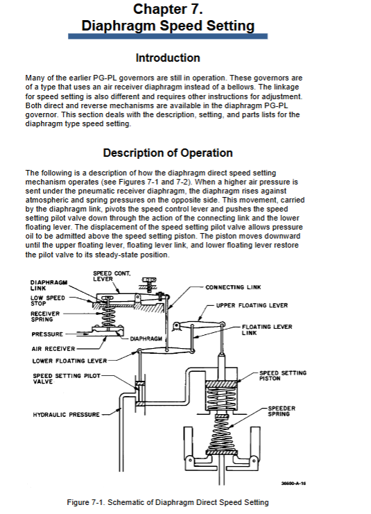
(2) Diaphragm speed regulation setting

Applicable scenario: Early PG-PL speed controller (using air receiver diaphragm instead of bellows)

Adjustment logic: Set the correspondence between air pressure and speed through sliding blocks, idle screws, and base speed adjustment nuts. The direct and reverse types require adjustment of the connecting rod arrangement

WOODWARD 2301A Speed Control Controller

​Product Overview

Product Name: Woodward 2301A Speed Control Controller

Core positioning: Provide high-precision speed and load control for various types of prime movers (engines, turbines), supporting single operation or parallel load distribution for multiple units

Core advantages:

Dual working modes: equal time mode (maintaining constant speed when load changes), deceleration mode (speed changes with load, adapted for parallel operation)

Wide adaptability: supports forward/reverse actuators, single/dual actuator drivers

High environmental tolerance: working temperature -40 to+85 ° C, anti vibration, electromagnetic interference protection

Safety requirement: An overspeed shutdown device independent of the controller must be equipped, and the use of the minimum fuel contact for emergency shutdown is prohibited

Key technical specifications

(1) Electrical parameters

Category specification remarks

Low input voltage: 10-40Vdc (12W); High voltage: 88-131Vac/90-150Vdc (12W) AC frequency 50-400Hz

Speed sensing magneto electric sensor (MPU), signal range 1.0-30Vrms, minimum starting signal 1.0Vrms (crankshaft speed)

Speed range corresponds to sensor frequency: 500-1500Hz, 1000-3000Hz, 2000-6000Hz, 4000-12000Hz. Internal dip switch selection

Adjustment accuracy speed fine adjustment ± 5% (100 Ω multi turn potentiometer), maximum speed reduction of 8% (2K potentiometer)-

Response characteristic ramp time: 1-22 seconds (idle to rated speed), deceleration ramp<1 second potentiometer adjustment

Output terminals 9 (+) and 10 (-) of the actuator support dual series drive (dual actuator) shielded wiring, with the shielding layer only grounded at the controller end

(2) Physical and environmental parameters

Characteristic specification remarks

Dimensions: Low voltage version: 215.9 × 174.6 × 65.1mm; High voltage version: 215.9 × 177.8 × 65.1mm Unit: mm, inches are marked in parentheses

The weight is not clearly marked, and the body material is sheet metal chassis-

Working temperature -40 ° C to+85 ° C No condensation, anti direct water spray

Vibration protection 10-300Hz, 2g acceleration, 30 minutes per axis in accordance with IEC68-2-6 standard

Impact protection: Drop 1 meter into concrete, 1 time on each of the 6 surfaces-

Installation process

(1) Installation preparation

Location selection: Good ventilation, reserved maintenance space, away from high voltage/high current equipment and EMI sources, prohibited from installation on the engine

Power requirements: Low voltage models need to be directly connected to batteries (low impedance), and it is prohibited to draw power from high-voltage sources through resistors/Zener diodes

Shielded wiring: All signal lines use twisted pair shielded cables, with the shielding layer only grounded at the controller end (length<5cm) and exposed wires<15cm

(2) Key wiring

Remarks on Terminal Function Wiring Requirements

Low voltage of power terminal: 1 (+), 2 (-); High voltage: 1 (L), 2 (N) grounding in accordance with local regulations

Sensor terminals 7 and 8 (non-polar) MPU sensor, shield layer connected to the grounding column below terminal 9

Dual actuator terminals 9 (+) and 10 (-) are connected in series

Speed reduction adjustment terminals 13 (wiper), 14 (cw), 15 (ccw) 2K potentiometers, if there is no need for speed reduction, do not wire them

Short circuit the speed adjustment terminals 11 and 12 if there is no need for adjustment

(3) Installation inspection

Visual inspection: The actuator connecting rod is not loose/stuck, the wiring conforms to the drawing, and the terminals are not damaged

Grounding check: The resistance between terminals 7-17 and the grounding column is infinite (except for power terminals that allow grounding)

Sensor inspection: The clearance between MPU and gear meets the requirements, and the signal is ≥ 1.0Vrms when the crankshaft rotates

Operation and adjustment

(1) Pre start settings

Parameter setting value remarks

Minimum rated speed (counterclockwise to the bottom) 10 turn potentiometer

Reset the middle position single turn potentiometer

Gain (GAIN) middle position single turn potentiometer, adjusting too quickly may cause speed fluctuations

Minimum slope time (counterclockwise rotation to the end) to avoid excessive torque

Minimum idle speed (counterclockwise to the bottom) single turn potentiometer

Maximum fuel limit for startup (clockwise needle rotation to the bottom). It is recommended to disable this function for the reverse actuator

(2) Key adjustment steps

Stable operation adjustment: If there is a fast fluctuation, the gain will be reduced; if there is a slow fluctuation, the reset will be increased. If it is still unstable, the actuator compensation can be adjusted

Dynamic adjustment: gradually increase the gain until the actuator is slightly unstable, then callback to stability, and reduce overshoot by increasing reset

Idle speed adjustment: Open the rated speed contact and adjust the idle potentiometer counterclockwise to the recommended speed

Speed reduction regulation: When running in parallel, set the no-load speed, full load speed, and no-load speed according to the formula, with a typical value of 5%

Start fuel limit adjustment: The forward actuator is set to rated speed voltage+30%, and the reverse actuator is set to -30%

Troubleshooting

Typical Symptoms, Common Causes, and Solutions

The prime mover cannot start, the actuator does not operate, the polarity of the power supply is reversed, the voltage is low, and the starting fuel limit is too low. Check the power supply (meets the rated value), adjust the starting fuel limit clockwise, and verify the wiring of the actuator

When starting the prime mover, if the overspeed ramp time is too short or the rated speed is set too high, increase the ramp time (clockwise adjustment), reset the rated speed, and check the actuator linkage

Unstable speed (no load/load changes), improper gain/reset adjustment, unshielded wiring, link jamming. Re adjust gain/reset, check shielded wiring, and troubleshoot link loosening/jamming

No speed signal MPU fault, wiring error, excessive gap. Measure MPU resistance (100-300 Ω), adjust sensor gap, and check wiring

XP POWER VFR05 series 5W wall mounted AC-DC power adapter

Product Overview

Product Name: VFR05 Series Wall Mounted AC-DC Power Adapter

Core positioning: To provide globally applicable and multi interface adaptable high-efficiency external power supplies for low-power electronic devices, solving the problem of plug adaptation for cross-border use

Core advantages:

Global universal: comes standard with replaceable US/UK/EU/AU plugs, no need for additional adapters, suitable for different regional power grids

Flexible interface: covering four mainstream interfaces: USB A, Mini USB B, Micro USB B, and DC Jack (5.5 × 2.1 × 12mm)

High energy efficiency and low power consumption: Complies with Level VI energy efficiency standards, supports Level VII upgrades, and has a no-load power consumption of ≤ 75mW

Physical specifications:

Body size: 37.0 × 55.1 × 42.9mm (1.45 “× 2.16” × 1.69 “)

Weight: 80g (0.28lb) (body only)

Output cable: Length 1500mm (59.0 inches), specifications VW-1 80 ° C 300V, 24 AWG

Model and Output Specification Table

Model Output Voltage Output Current Total Adjustment Efficiency Output Interface Output Power Remarks

VFR05US050-BB 5.0V 1000mA ±5% 77% USB A in case 5W –

VFR05US050-MB 5.0V 1000mA ± 5% 74% Mini USB B 5W only available for OEM bulk supply

VFR05US050-UB 5.0V 1000mA ±5% 74% Micro USB B 5W –

VFR05US050-JA 5.0V 1000mA ±5% 75% 5.5×2.1×12mm DC Jack 5W –

VFR05US090-JA 9.0V 550mA ±5% 78% 5.5×2.1×12mm DC Jack 5W –

VFR05US120-JA 12.0V 420mA ±5% 79% 5.5×2.1×12mm DC Jack 5W –

Electrical parameter details

(1) Input parameters

Characteristic Minimum Value Typical Value Maximum Value Unit Remarks

Input voltage 90-264 VAC covering the global 110V/220V power grid

Input frequency 47-63 Hz compatible with different regional power grid frequencies

Power factor – compliant with EN61000-3-2 Class A

Input current -0.18 A under 100VAC input conditions

Surge current -30 A 240VAC cold start, 25 ° C environment

No load input power -75 mW high energy efficiency design, low standby power consumption

Input protection – built-in T1.0A/250VAC fuse

(2) Output parameters

Characteristic Minimum Value Typical Value Maximum Value Unit Remarks

Output voltage range of 5-12 VDC differentiated by model to meet different equipment requirements

Minimum load – No minimum load requirement, suitable for low-power devices

Startup delay -4 seconds-

Start up time -50-ms-

Hold time -8ms full load, 100VAC input

Total regulation -5% including initial setting accuracy, line regulation, and load regulation

Transient response -4% deviation 5V model 25% load step, other models 50% load step, restored to ± 1% within 500 µ s

Ripple and noise -200 mV pk pk 20MHz bandwidth, requiring parallel measurement of 10 µ F electrolytic capacitor and 0.1 µ F ceramic capacitor

Temperature coefficient -0.05%/° C, high stability of output voltage

Short circuit protection – continuous hiccup mode, automatically restored after troubleshooting

(3) General and reliability parameters

Characteristic Minimum Value Typical Value Maximum Value Unit Remarks

Efficiency 74-79% under 115VAC input, average load efficiency of 25%/50%/75%/100%

Energy Efficiency Standard – Level VI – Supports Level VII Upgrade, Energy saving and Environmental Protection

Input output isolation -3000VAC ensures safe use

Switching frequency 50-70 kHz variable frequency design

Mean Time Between Failures (MTBF) 100- khrs MIL-HDBK-217F standard, 25 ° C environment

Environment and Compliance

(1) Environmental adaptability

Minimum environmental conditions, typical values, maximum values, unit notes

Full load at working temperature 0-60 ° C and 50 ° C, reduced to 50% load at 60 ° C

Storage temperature -40-85 ° C, suitable for extreme storage environments

Cooling method – natural convection – no additional cooling equipment required

Working humidity 5-95% RH non condensing, suitable for humid environments

Impact – Drop to concrete from a height of 1 meter, 1 time on each of the 6 surfaces

Vibration 10-300 Hz 2g acceleration, 30 minutes per axis (15 minutes/scan)

(2) Compliance and Certification

Key Explanation of Certification Type Standards

UL/cUL62368-1, EN61000-3-2, IEC62368-1 safety certification approved as Limited Power Source (LPS)

Regional certifications CCC (China), AU/NZ 62368.1 (Australia and New Zealand), CE (European Union), UKCA (United Kingdom) cover major global markets

EMC emissions EN55032, FCC Part 15 Subpart B conduction/radiation all reach Level B, harmonic class A

EMC immunity EN61000-4 series, EN55035 ESD ± 4kV contact/± 8kV air, radiation immunity 3V/m

XP POWER VFL05 series AC-DC power adapter

Product Overview

Product Name: VFL05 Series Wall Mounted AC-DC Power Adapter

Core positioning: To provide a universal, efficient, and adaptable external power supply for low-power electronic devices, balancing global grid compatibility and multi scenario interface requirements

Core advantages:

Global compatibility: 90-264VAC wide input covering 110V/220V power grid, four types of plugs suitable for different regions

Flexible interface: Supports four output interfaces: USB A, Mini USB B, Micro USB B, and DC Jack, suitable for different devices

High energy efficiency and low power consumption: compliant with Level VI energy efficiency standards, no-load power consumption ≤ 75mW, energy-saving and environmentally friendly

Physical specifications:

Weight: 80g (0.28lb)

Output cable length: 1500mm (59.0 inches)

Cable specification: VW-1 80 ° C 300V, 24 AWG

Size: Due to slight differences in plug types, the typical size is 55.1 × 35.49 × 24.1mm (taking US plug as an example)

Model and Output Specification Table

Plug type, model, output voltage, output current, output interface, overall regulation efficiency

US VFL05US050-US-BB 5.0V 1000mA USB A in case ±5% 77%

US VFL05US050-US-MB 5.0V 1000mA Mini USB B ±5% 74%

US VFL05US050-US-UB 5.0V 1000mA Micro USB B ±5% 74%

US VFL05US050-US-JA 5.0V 1000mA 5.5×2.1×12mm DC Jack ±5% 75%

US VFL05US090-US-JA 9.0V 550mA 5.5×2.1×12mm DC Jack ±5% 78%

US VFL05US120-US-JA 12.0V 420mA 5.5×2.1×12mm DC Jack ±5% 79%

EU VFL05US050-EU-BB 5.0V 1000mA USB A in case ±5% 77%

EU VFL05US050-EU-MB 5.0V 1000mA Mini USB B ±5% 74%

EU VFL05US050-EU-UB 5.0V 1000mA Micro USB B ±5% 74%

EU VFL05US050-EU-JA 5.0V 1000mA 5.5×2.1×12mm DC Jack ±5% 75%

EU VFL05US090-EU-JA 9.0V 550mA 5.5×2.1×12mm DC Jack ±5% 78%

EU VFL05US120-EU-JA 12.0V 420mA 5.5×2.1×12mm DC Jack ±5% 79%

UK VFL05US050-UK-BB 5.0V 1000mA USB A in case ±5% 77%

UK VFL05US050-UK-MB 5.0V 1000mA Mini USB B ±5% 74%

UK VFL05US050-UK-UB 5.0V 1000mA Micro USB B ±5% 74%

UK VFL05US050-UK-JA 5.0V 1000mA 5.5×2.1×12mm DC Jack ±5% 75%

UK VFL05US090-UK-JA 9.0V 550mA 5.5×2.1×12mm DC Jack ±5% 78%

UK VFL05US120-UK-JA 12.0V 420mA 5.5×2.1×12mm DC Jack ±5% 79%

AU VFL05US050-AU-BB 5.0V 1000mA USB A in case ±5% 77%

AU VFL05US050-AU-MB 5.0V 1000mA Mini USB B ±5% 74%

AU VFL05US050-AU-UB 5.0V 1000mA Micro USB B ±5% 74%

AU VFL05US050-AU-JA 5.0V 1000mA 5.5×2.1×12mm DC Jack ±5% 75%

Note: The 9V and 12V models of EU/UK/AU plugs are only available for OEM bulk supply and require confirmation from sales.

Electrical parameter details

(1) Input parameters

Characteristic Minimum Value Typical Value Maximum Value Unit Remarks

Input voltage 90-264 VAC-

Input frequency 47-63 Hz-

Power factor – compliant with EN61000-3-2 Class A

Input current -0.18 A 100VAC input

Surge current -30 A 240VAC cold start, 25 ° C

No load input power -75 mW-

Input protection – built-in fuse

(2) Output parameters

Characteristic Minimum Value Typical Value Maximum Value Unit Remarks

Output voltage range 5-12 VDC differentiated by model

Minimum load – No minimum load requirement

Startup delay -4 seconds-

Start up time -50 ms-

Hold time 8– ms full load, 100VAC input

Total regulation -5% including initial setting accuracy, line regulation, and load regulation

Transient response -4% deviation 5V model 25% load step, other models 50% load step, restored to ± 1% within 500 µ s

Ripple and noise -200 mV pk pk 20MHz bandwidth, parallel 10 µ F electrolytic capacitor+0.1 µ F ceramic capacitor

Temperature coefficient -0.05-%/° C-

Short circuit protection – continuous hiccup mode, automatic recovery

(3) General and reliability parameters

Characteristic Minimum Value Typical Value Maximum Value Unit Remarks

Efficiency 74-79% by model, with an average load of 25%/50%/75%/100% under 115VAC input

Energy Efficiency Standard – Level VI (Level VII ready)

Input output isolation 3000– VAC-

Switching frequency 50-70 kHz, variable frequency

Mean Time Between Failures (MTBF) 100- khrs MIL-HDBK-217F standard, 25 ° C

Environment and Compliance

(1) Environmental adaptability

Minimum environmental conditions, typical values, maximum values, unit notes

Full load at working temperature 0-60 ° C and 50 ° C, reduced to 50% load at 60 ° C

Storage temperature -40-85 ° C-

Cooling method – natural convection —

Working humidity -95% RH non condensing

Impact – Drop to concrete from a height of 1 meter, 1 time on each of the 6 surfaces

Vibration -10-300Hz, 2g, 30 minutes per axis (15 minutes/scan)

(2) Compliance and Certification

Certification Type Standards/Directive Key Requirements

UL/cUL62368-1, EN61000-3-2, IEC62368-1 safety certification approved as Limited Power Source (LPS)

Regional certifications CCC (China), AU/NZ 62368.1 (Australia and New Zealand), CE, UKCA comply with corresponding regional regulations

EMC emissions EN55032, FCC Part 15 Subpart B Conducted/Radiated Level B, Harmonic Class A

EMC immunity EN61000-4 series, EN55035 ESD ± 4kV contact/± 8kV air, radiation immunity 3V/m

XP POWER AQM200 series AC-DC external power supply

Product Overview

Product Name: AQM200 Series Medical Grade AC-DC External Power Supply

Core positioning: A high power density, low noise, compliant external power supply designed specifically for medical scenarios, meeting the needs of both hospitals and home medical use

Core advantages:

Strong compliance: Passed international medical safety certification and the latest energy efficiency standards, with low leakage current (patient leakage current ≤ 100 µ A)

Practical design: Natural cooling without the need for a fan, fully sealed enclosure with IP22 protection, smooth and easy to clean surface, suitable for clinical environments

Flexible adaptation: Supports Class I (with grounding) and Class II (double insulation) versions to meet different installation requirements

Physical specifications:

Size: 166.5 × 54.2 × 33.0mm (6.56 “× 2.13” × 1.30 “)

Weight: 600g (1.32lbs)

Output interface: Kycon KPPX-4P type, cable length 1200mm (12V/15V), 1500mm (other models)

Input interface: IEC320-C14 (Class I), IEC320-C18 (Class II optional)

Electrical parameter details

(1) Input parameters

Characteristic Minimum Value Typical Value Maximum Value Unit Remarks

When the input voltage is 85-264 VAC, the load is reduced to 85% and restored to 100% at 100VAC

Input frequency 47-63 Hz-

Power factor ->0.9- compliant with EN61000-3-2 Class A

Input current -2.4/1.0-A 115VAC/230VAC full load

Surge current -150 A 230VAC cold start, 25 ° C

Ground leakage current -500 µ A 264VAC/60Hz, Class I version only

No load input power -0.15 W-

Input protection – built-in T5A/250V fuse (live wire+neutral wire)

(2) Output parameters

Model Output Voltage Output Current Average Efficiency Total Adjustment

AQM200PS12 12.0VDC 16.0A 91.5% ±5.0%

AQM200PS15 15.0VDC 13.0A 92.0% ±5.0%

AQM200PS19 19.0VDC 10.6A 92.0% ±5.0%

AQM200PS24 24.0VDC 8.3A 93.0% ±5.0%

AQM200PS48 48.0VDC 4.2A 93.5% ±5.0%

Characteristic Minimum Value Typical Value Maximum Value Unit Remarks

Initial setting accuracy – ± 2% 50% load

Minimum load – No minimum load requirement

Start delay -1.5 seconds-

Start up time -30 35 ms 115VAC input

Hold time 10 12 ms full load, 115/230VAC

Line adjustment – ± 0.5% 90-264VAC input

Transient response -4% 50-75%/75-50% load step, restored to ± 1% within 500 µ s

Ripple and noise -1.0% pk pk 20MHz bandwidth, parallel 10 µ F electrolytic capacitor+0.1 µ F ceramic capacitor

Overshoot -5 10% during startup/shutdown

Overload protection -180%-

Short circuit protection – hiccup mode, automatic recovery

Temperature coefficient -0.2%/° C-

Patient leakage current -85 100 µ A 264VAC/60Hz

(3) General and reliability parameters

Characteristic Minimum Value Typical Value Maximum Value Unit Remarks

Isolation voltage -4000 VAC input-output (2 x MOPP)

–1800 VAC input ground (1 x MOPP, Class I only)

–500- VAC output – Ground (Class I only)

Switching frequency 45 kHz PFC circuit

200-300 kHz main converter

Power density -27.94- W/cm ³-

Mean Time Between Failures (MTBF) ->300- khrs TELCORDIA SR-322 standard, 25 ° C

Environment and Compliance

(1) Environmental adaptability

Minimum environmental conditions, typical values, maximum values, unit notes

Working temperature -20-60 ° C, linear derating after 40 ° C, with a load of 50% at 60 ° C

Cooling method – natural convection —

Working humidity 20-80% RH non condensing

Storage humidity 10-90% RH non condensing

Storage temperature -20-80 ° C-

Working altitude -5000 meters-

Shock – IEC68-2-27, 30g, 11ms half sine wave, 3 times on each of the 6 axes

Vibration – IEC68-2-6, 10-500Hz, 2g, 60 minutes per axis (10 minutes/scan)

(2) Compliance and Certification

Certification Type Standards/Directive Key Requirements

Medical Safety ANSI/AAMI ES 60601-1, CSA C22.2 No. 60601-1, EN60601-1 comply with medical electrical safety requirements

Home healthcare EN60601-1-11 is only applicable to Class II version

EMC compliance EN55011 (Conducted/Radiated), EN61000-3-2/3 Conducted Level B, Harmonic Class A

EMC immunity EN61000-4 series, EN60601-1-2 ESD ± 8kV contact/± 15kV air, radiation immunity 10V/m

Energy Efficiency Level VI, EU CoC tier 2 standby power consumption<0.15W

Other certifications CB, CE, UKCA comply with corresponding regional regulatory requirements

Mechanical and Interface Details

Output cable pin allocation: P1 (+Vout), P2 (+Vout), P3 (Rtn), P4 (Rtn)

Output interface shell: Class I version connection – Vout, Class II version suspended

Dimensional tolerance: Except for the length of the output cable, the tolerance for other dimensions is ± 0.5mm (± 0.02 inches)

XP POWER CB Series DC-HVDC Converter

​Product Overview

Product Name: CB Series Miniature High Voltage DC-HVDC Converter

Core positioning: To provide clean and stable high-voltage power supply for compact, precision sensitive equipment, while balancing low noise and high programmability

Core advantages:

High voltage output: supports 0-+10kV (CB101) and 0-10kV (CB101N) to meet the requirements of high voltage applications

Precise control: 0-5VDC programming voltage achieves 0-100% output regulation, with a set point accuracy of ± 1%

Reliable design: Natural cooling without the need for a fan, shielded casing to reduce EMI/RFI, thermal shutdown protection to prevent overheating

Physical specifications:

Size: 3.00 x 1.25 x 0.60 inches (76.2 x 31.8 x 15.2mm)

Weight: 3oz (85g)

Shell Material: Galvanized Steel, UL94 V-0 Solid Vacuum Encapsulation

Installation method: 8-pin PCB installation, equipped with 2 mounting holes (# 2/M2 specifications)

Electrical parameter details

(1) Input parameters

Characteristic Minimum Value Typical Value Maximum Value Unit Remarks

Input voltage (Vin) 11.5 12.0 16.0 VDC-

No load input current -100 mA-

Full load input current -225 mA-

Input capacitance -440- μ F-

Programming voltage (Vpgm) 0-+5 VDC input current<100 μ A

Programming overvoltage protection -+5.25 VDC-

(2) Output parameters

Characteristic Minimum Value Typical Value Maximum Value Unit Remarks

Output voltage range 0- ± 10 kV CB101 forward, CB101N reverse

Output current – at a maximum output voltage of 100 μ A

Output adjustment range 0-100% corresponds to programming voltage 0-5VDC

Setpoint accuracy – ± 1-% after preheating for 1 hour

Gain adjustment range – ± 1-% potentiometer adjustment

Linearity – ± 1% 20% -100% output range

Line regulation -0.1% 100% programming voltage, full load

Load regulation -0.1% no-load to full load, 100% programming voltage

Ripple and noise -0.1% 1MHz bandwidth

Temperature coefficient -50 ppm/° C-

Short term stability -100 ppm/hr-

Response time -250 milliseconds 10% -90% full load output

Reference voltage output -+5- VDC accuracy ± 1%, output current 2mA

Voltage monitoring output 0-+5 VDC error<0.5% (20% -100% output)

Current monitoring output 0-+5 VDC error<0.5% (20% -100% output)

(3) General and reliability parameters

Characteristic specification remarks

Isolation design connects the input ground to the output ground-

Switching frequency 100-150kHz, typical value 150kHz

Mean Time Between Failures (MTBF) 2.6 MHz Bellcore TR 332 standard,+25 ° C

Thermal shutdown temperature+85 ° C automatic protection

Pin definition: 8-pin+high voltage output lead, including input, ground, programming, monitoring and other functions

Environment and Compliance

(1) Environmental adaptability

Environmental condition specification remarks

Working temperature -10 ° C to+60 ° C Shell temperature

Storage temperature -20 ° C to+100 ° C-

Working humidity 95% RH non condensing

Thermal shock limit 1 ° C/10 seconds-

The cooling method is naturally convection cooled, which does not require additional heat dissipation equipment

(2) Compliance and Certification

Project specification remarks

Packaging grade UL94 V-0 solid vacuum packaging

Galvanized steel shielding for shell protection reduces EMI/RFI interference

Grounding requirements: The shell grounding (Pin3) must be grounded and the potential difference between the circuit grounding (Pin2) must be ≤ 50V

Function and Usage Instructions

(1) Core functions

Programming adjustment: achieve 0-100% output adjustment through external signals of 0-5VDC or onboard 5V reference voltage (with potentiometer), the formula is V OUT= R1+R3/R1(10000)

Monitoring function: Voltage monitoring (VMON pin) and current monitoring (IMON pin) both output 0-5VDC signals, linearly corresponding to 0-100% output

Protection function: Built in programming overvoltage protection (≤ 5.25VDC), thermal shutdown protection (+85 ° C), to prevent equipment damage

(2) Pin definition

Pin Number Function Description Key Parameters

Input voltage (Vin) 11.5-16VDC

2 Signal Ground (SGND) Circuit Reference Ground

CGND must be grounded, with a potential difference of ≤ 50V between CGND and SGND

4 Programming Voltage Input (VPGM) 0-5VDC,<100 μ A

5 reference voltage output (VREF)+5VDC ± 1%, 2mA

6 Current Monitoring Output (IMON) 0-5VDC, corresponding to 0-100% output current

7 Voltage Monitoring Output (VMON) 0-5VDC, corresponding to 0-100% output voltage

8 High Voltage Return (HV RTN) High Voltage Output Circuit

Lead high voltage output (HV OUT) # 22 AWG 20kV silicon wire

XP POWER CDX Series 1500W Dual Frequency RF Power Supply

Product Overview

Product Name: CDX Series Dual Frequency RF Power Supplies

Core positioning: High power, high-precision power supply equipment designed for industrial scenarios that require dual frequency RF drive, such as semiconductors, plasma processing, etc

Core advantages: flexible dual band selection, high output accuracy and stability, multi communication interface adaptation, compatibility with harsh environments and compliance

Physical and installation characteristics:

Dimensions: 483mm x 133mm x 457mm (19 “W x 5.25” H x 18 “D)

Weight: Maximum 18kg (39lb.)

Installation method: Standard 19 inch EIA rack mounted

Appearance: Full surface painted or galvanized chromate coating, equipped with dual handles at the front end

Warning signs: IEC standard safety signs including dangerous voltage, heavy objects, high temperature, and radio frequency energy

Electrical specification details

(1) Input parameters

Characteristic specification remarks

Input voltage 208/400/480VAC, three-phase without neutral wire, with grounding

Input frequency 50/60Hz nominal value

Input current 7.5A/phase based on 480VAC input, varying with output specifications

(2) Output parameters

Characteristic specification remarks

Single output power up to 1500W continuous forward power, 50 Ω load

Output accuracy/adjustment ± 2W or ± 1.0% (whichever is greater) 10% -100% maximum output range

Short term stability ± 1.0% continuous output for 1 hour, 10% -100% set point

Long term stability ± 3.0% continuous output for 3 years, 10% -100% set point

Rise time<200ms from enable signal front to 90% requested power

Available frequencies (per channel): 400kHz, 2MHz, 13.56MHz, 27.12MHz, 40.68MHz, 60MHz. Any two frequencies can be selected

Frequency stability ± 0.005%-

Zero set point output<1.0W actual power,<1.0W read back power when the set signal is zero or negative

Harmonic signal<-40dBc-

Stray signal<-40dBc-

AM&FM noise<-40dBc at 50kHz offset

Heat dissipation and environmental requirements

(1) Heat dissipation parameters

Detailed remarks on heat dissipation method requirements

Cooling type: mandatory requirement for water cooling, alternative option without air cooling

The minimum inlet flow rate is 8.6L/m (2GPM) and the maximum pressure is 414kPa (60psi)

Inlet water temperature: 5 ° C-25 ° C (40 ° F-77 ° F). Water temperature exceeding the range may affect heat dissipation efficiency

Explanation on no special water quality requirements for cooling medium water

(2) Environmental adaptability

Environmental conditions, work scope, storage/transportation scope

Temperature 10-40 ° C (50-104 ° F) -25-70 ° C

Humidity 5-85% RH (non condensing, non freezing) 5-95% RH (non condensing, non freezing)

Air pressure 86-106kPa 70-106kPa

The maximum intake requirement is 30 ° C (95 ° F)-

Standard Class Temperature/Humidity/Air Pressure Class 3K3 (prEN50178) Temperature Class 1k4, Humidity Class 1k3, Air Pressure Class 1k4

Function and Interface

(1) Core functions

Optional features: Pulse mode operation (single-stage/multi-stage/synchronous/advanced envelope control), frequency agility, automatic frequency tuning (minimizing reflected power), fast shutdown (arc management), common exciter (CEX, multi power synchronous clock)

Safety and status monitoring: Front end LED indicator lights (AC on, RF on, interlock status, fault status), 20 × 2 character alphanumeric display screen (displaying all operating parameters)

(2) Communication and Connection Interface

Interface Type Specification Details Usage

Digital communication DeviceNet (M12 interface), EtherCAT industrial bus control and data transmission

Serial communication RS232 point-to-point serial control

Analog interface, analog signal input/output, analog quantity control, and power feedback

Other interfaces include 15PIN I/O, 10-32 grounding column, HARTING/HAN 40 3PE (power input) expansion I/O, grounding, and power access

Compliance and Certification

Safety compliance: EN 61010-1:2010, UL 61010-1:2012, CSA C22.2 No. 61010-1:2012

Performance compliance: Passed SEMI F47-0200 voltage drop immunity test to meet Samsung Power Vaccine requirements

Certification mark: Compliance system with TUV safety/EMC mark (compliant with the latest international standards)

image.png

XP POWER RDF25 Series 5W Bottom Cooling DC-DC Converter

Product Overview

Product Name: RDF25 Series DC-DC Converter

Core positioning: A high reliability bottom plate cooling power supply designed specifically for wide input voltage scenarios, suitable for harsh environments such as industry and railways

Core advantages: Ultra wide input range, high isolation, wide temperature operation, multiple protections, supporting flexible configuration and expansion

Packaging and Material:

Packaging: Industrial standard half brick, size 50.8 × 25.4 × 11.5mm (2.0 “× 1.0” × 0.45 “)

Shell: Copper shell+UL94V-0 grade non-conductive plastic base

Sealing material: UL94V-0 grade epoxy resin, compliant with EN45545-2 fire smoke standard

Electrical parameter details

(1) Input parameters

Characteristic specification remarks

Input voltage range 16-160VDC 10:1 ultra wide range, covering standard industrial voltages

Measurement under nominal input voltage with no-load input current of 10mA

When the standby current 3mA module is disabled

Input filtering Pi type filtering suppresses input interference

Input protection requires external 3A delay fuse+TVS tube surge protection and reverse voltage protection

(2) Output parameters

Model Output Voltage Output Current Maximum Capacitive Load Efficiency

RDF2572S05 5VDC 5.0A 6800µF 85%

RDF2572S12 12VDC 2.08A 1000µF 84%

RDF2572S15 15VDC 1.67A 820µF 85%

RDF2572S24 24VDC 1.04A 470µF 85%

Voltage fine-tuning with ± 10% external resistance to achieve voltage rise and fall-

Temperature coefficient 0.02%/° C, output voltage stability-

Overvoltage protection with 120% Vnom Zener diode clamp and automatic recovery-

(3) General and reliability parameters

Characteristic specification remarks

Input output isolation 3000VDC (60s) basic isolation

Under the condition of isolation resistance ≥ 10 ΩΩ 3kVDC

Isolation capacitor 2000pF-

Switching frequency 250kHz-

Power density 28W/in ³-

Mean Time Between Failures (MTBF) 230khrs MIL-HDBK-217F,+25 ° C GB

Weight standard 36g, with radiator 47g-

Environment and Compliance

(1) Environmental adaptability

Basis for environmental condition specification standards

Working temperature -40 ° C to+100 ° C-

Storage temperature complies with IEC/EN 60068-2-1-

Humidity 95% RH non condensing

Working altitude 5000m-

Shock and vibration comply with IEC/EN 61373, suitable for transportation and industrial environments

Dry heat/humid heat in accordance with IEC/EN 60068-2-2/30-

(2) Compliance and Certification

Certification Type Standards/Directive Key Requirements

Safety certification EN50155, CE, UKCA railway and general safety compliance

EMC emission EN50121-3-2 conduction+radiation compliance

EMC Immunity EN50121-3-2 Conducted Immunity 10Vrms, Static ± 2kV

Welding compliance IPC JEDEC J-STD 020D. 1 up to 260 ° C for 10 seconds

Function and Usage Instructions

(1) Core functions

Remote switch: high level (3.0-12.0VDC) on, low level (0-1.2VDC) off, control pin3 to be suspended when not in use

Fine tuning of output voltage:

Boosting: Trim pin and – Vout indirect resistor Ru (refer to the selection table in the document)

Voltage reduction: Trim pin and+Vout indirect resistor Rd (refer to the document table for selection)

Protection mechanism: overvoltage (Zener clamp), overload (current limit), short circuit (automatic recovery)

(2) Installation and selection

Heat sink: Optional model with suffix “- HK” added to enhance heat dissipation capability in high temperature environments

Input configuration: An external 3A delay fuse and TVS tube must be connected to prevent damage from surges and reverse voltages

Pin definitions: 1-pin (+Vin), 2-pin (- Vin), 3-pin (Control), 4-pin (+Vout), 5-pin (- Vout), 6-pin (Trim)

Application scenarios

Autonomous Equipment

Industrial Electronics&Robotics

Railway equipment

Renewable energy systems, battery systems, and harsh environmental equipment

XP POWER ITX Series 6W DC-DC Converter

​Product core positioning

Product type: DC-DC converter

Power level: 6W

Package specification: SIP8 PCB installation plastic shell, size 21.85 × 11.1 × 9.2mm (0.86 “× 0.44” × 0.36 “), weight approximately 4.8g (0.011lb)

Warranty period: 3 years

Application scenario: Independent industrial technology equipment

Key electrical parameters

(1) Input parameters

Characteristic specification remarks

The input voltage range is 4.5-9VDC, 9-18VDC, 18-36VDC, and 36-75VDC, all with a 2:1 input ratio, corresponding to nominal 5VDC, 12VDC, 24VDC, and 48VDC

Input reflection ripple up to 30mA pk pk measured through a 12 µ H inductor and a 47 µ F capacitor

Input surge 15VDC/100ms (5VDC nominal), 25VDC/100ms (12VDC nominal), 50VDC/100ms (24VDC nominal)-

No load input current  15mA(36-75VDC)、30mA(18-36VDC)、55mA(9-18VDC)、105mA(4.5-9VDC)  Measurement under nominal input voltage

(2) Output parameters

Characteristic specification remarks

Output voltage single output: 3.3/5/9/12/15/24VDC; Dual output: ± 5/± 12/± 15VDC Different models correspond to different outputs

Output current single output: 250mA-1300mA; Dual output: ± 200mA – ± 600mA depending on the output voltage (see model table for details)

Initial output accuracy setting ± 1%, line adjustment rate ± 0.2%, load adjustment rate ± 1%, load adjustment rate based on 0-100% load variation

Dual output balance maximum ± 2%, only available for dual output models

The maximum cross adjustment rate is ± 5% for dual output models, with one load varying from 25% to 100% and the other load being 100% fixed

Transient response with a maximum deviation of 3% (maximum 5% for 3.3/5V models) and a 25% load change, recovering to ± 1% within 500 µ s

Ripple and noise maximum 75mV pk pk 20MHz bandwidth, measured by 0.1 μ F ceramic capacitor

Maximum capacitive load 680 µ F-6600 µ F corresponds to different values for different models (see model table for details)

Minimum load 0%, stable operation without minimum load required

(3) Isolation and efficiency

Isolation performance: Input/output standard isolation 1500VDC, optional 3000VDC (model suffix plus “- H”); The minimum isolation resistance is 10 Ω, and the maximum isolation capacitance is 50pF

Efficiency: 77% -86%, different models have different efficiencies (e.g. ITX0503SA is 77%, ITX4815S is 85%)

(4) Protection and control functions

Short circuit protection: continuous protection, automatic recovery

Remote switch: optional function, model suffix plus “- R”; Output shutdown: Input 2-4mA (relative to – Vin) to pin 3 through a 1K Ω resistor; Output enabled: open circuit or high impedance

Environmental and Physical Characteristics

Temperature range: Operating temperature -40 ° C to+90 ° C (+65 ° C or above is reduced to 20% load); 5V and ± 5V models+derating to 20% load above 55 ° C); Storage temperature -55 ° C to+125 ° C; maximum shell temperature 105 ° C

Humidity: Maximum 95% RH, non condensing

Cooling method: natural convection

Physical dimensions: 21.85 × 11.1 × 9.2mm, pin spacing of 2.54mm, pin diameter of 0.5 ± 0.05mm

Power density: 2.6W/cm ³ (44.0W/in ³)

Mean Time Between Failures (MTBF): 770 khrs (MIL-HDBK-217F,+25 ° C GB)

Security and EMC Compliance

Emission standard: Complies with EN55032 Class A (conducted emission)

Immunity standard: Radiation immunity EN61000-4-3 (20V/m A); Surge immunity EN61000-4-5 (3B/2B, requires external input of 330 µ F/100V capacitor); Conducted immunity EN61000-4-6 (3Vrms A)

Input filtering: It needs to be matched with specified capacitors (C1 to C5) and inductors (L), and the components should be installed close to the module to reduce radiated noise

Model Naming Rules

Example of suffix function

-H optional 3000VDC high isolation ITX1205SA-H

-R optional remote control function ITX2412S-HR

XP Power Supply Technical Guide

Analysis of Core Technology Modules

(1) Basic Theory of Power Supply

Technical points, core content, key parameters/standards

Power type linear power supply: low noise (suitable for audio equipment), low efficiency, large size;

Switching power supply: High frequency switching (200kHz-1MHz), high efficiency (up to 91%), small size, linear power supply efficiency<60%; Switching power supply efficiency 75% -91%

Topology flyback converter (≤ 150W), forward converter (100-300W), half bridge (150-1000W), full bridge (>1000W), boost converter (PFC application), flyback converter has high ripple current; The full bridge converter has the highest power density

Distributed Power Architecture (DPA) front-end power supply → intermediate bus → load point DC-DC converter, supports hot swapping, redundant backup intermediate bus voltage 48VDC, allows ± 10% fluctuation

(2) Key technologies for input design

Power source:

AC power supply: single-phase (85-264VAC), three-phase (star/delta connection), global frequency 50/60Hz

DC power supply: battery (lead-acid/NiCd/NiMH/Li ion), DC generator (12/24/48VDC)

Input protection:

Surge/transient protection: GDT (gas discharge tube), MOV (metal oxide varistor), compliant with EN61000-4-5 (± 2kV common mode)

Surge current limit: NTC thermistor, cold start surge current 30-40A (continuous 1-2ms)

Reverse polarity protection: series diodes (no fuse), parallel diodes (fuse protection)

Harmonic suppression:

Passive PFC: suitable for ≤ 300W, power factor 0.5-0.6

Active PFC: suitable for>100W, power factor>0.9, compliant with EN61000-3-2 Class A/B

Grounding design:

Functional grounding (FE): No safety function; Protective grounding (PE): Anti electric shock (Class I system)

Creepage/electrical clearance: basic insulation ≥ 2.0mm, double insulation ≥ 4.0mm (300VAC)

(3) Output key design technologies

Core parameters:

Output voltage: 3.3-60VDC (standard), series connection can be extended to higher voltages

Ripple noise: ≤ 50mV pk pk (3.3-9V models), ≤ 0.5% pk pk (other models), 20MHz bandwidth measurement

Adjustment accuracy: Line adjustment ≤ 0.1%, load adjustment ≤ 0.6%

Output protection:

Overvoltage protection (OVP): 115% -140% Vnom, automatic recovery/locking

Overload protection: constant current limit, constant power limit, hiccup mode, turn back current limit

Short circuit protection: Trip restart (hiccup mode), no risk of damage

Operation mode:

Series operation: requires constant current limitation and reverse diode protection

Parallel operation: active current sharing (error ± 10%), supporting N+M redundancy

Redundant operation: ORing diode, supports hot swapping, ensures continuous power supply

Status and Control:

Status signals: AC OK (power supply normal), DC OK (output normal), over temperature alarm

Control interface: remote switch, voltage programming (0-5V corresponds to 0-100% output), current sharing control

(4) Specialized product technology

Product Type Application Scenarios Key Parameters

UPS system critical load backup power supply online (0ms switching), interactive (2-10ms switching), offline (2-10ms switching), capacity 250VA-800kVA

DC/AC inverter DC to AC output waveform (sine wave/quasi sine wave), input 12/24/48VDC, surge capacity 20% -300% (continuous for 3-15s)

Frequency Converter Frequency Conversion (50/60/400Hz) Static Converter (AC-DC-AC), suitable for aviation electronic equipment

Static switch (STS) dual power switching time<1/4 cycle, efficiency>99%, no mechanical wear and tear

(5) Thermal Management and Reliability

Thermal management:

Heat dissipation methods: natural convection (≤ 100W), forced air cooling (100-2000W, 12-48CFM), bottom plate heat dissipation (high temperature environment)

Fan selection: Calculated based on power loss, formula: airflow (m ³/hr)=2.6 × power (W)/allowable temperature rise (° C)

Capacitor lifespan: For every 10 ° C decrease, the lifespan doubles

Reliability:

Failure analysis: bathtub curve (early failure → stable period → loss period)

MTBF calculation: MIL-HDBK-217/F standard, typical value 500000 hours (25 ° C)

Influencing factors: complexity (number of components), stress (temperature/voltage), device selection (universal reliability)

Regulatory and compliance requirements

Security certification:

IT/Industry: IEC62368-1, UL62368-1, EN62368-1

Medical: IEC60601-1 (BF/CF grade), leakage current ≤ 10 µ A (CF grade)

Asian markets: CCC (China), BSMI (Taiwan), PSE (Japan), KETI (South Korea)

EMC Compliance:

Emission limits: CISPR22 Class B (conduction), Class A (radiation)

Immunity: ESD (± 8kV air discharge), EFT (± 2kV industrial grade), voltage drop (30%/60%/95%)

Energy Efficiency Standards:

CEC 2008: No load power consumption ≤ 0.5W (<10W), ≤ 0.75W (10-250W), efficiency ≥ 0.85 (>49W)

EU Code of Conduct: No load power consumption ≤ 0.3W (<15W), ≤ 1.0W (60-150W), efficiency ≥ 0.9 (25-150W)

Military standards:

MIL-STD 461E/F: EMC Emission/Immunity

MIL-STD 1275: Vehicle Power Supply (25-33VDC)

DEF STAN 59-41: British Standard Military Power Supply

Engineering Practice and Technical Topics

Battery selection and sizing:

Type comparison: Lead acid (low-cost, heavy), Li ion (high energy density, requiring protection), NiCd (wide temperature range, toxic)

Capacity calculation: Constant current method (Ah=current x time), taking into account temperature derating (derating from 0 ° C to 80%) and lifespan factor (x 1.25)

5 technical topics:

Configurable power topology: based on 380VDC bus, supports 14 outputs, power range 450W-2400W

Small and efficient AC-DC design: resonant topology+synchronous rectification, efficiency up to 91%, power density 10.55W/in ³

Compact and flexible power supply: Fractional Turn Transformer (FTT), reduces cross regulation, supports 3.3-60VDC output

Synchronous rectification technology: MOSFET replaces diode, reducing losses by 44%, suitable for low voltage (3.3/5V)

Military COTS power supply: based on commercial modules, meets -40 ° C low temperature, MIL-STD compliance, cost reduction of 30%

Search for products

Back to Top
Product has been added to your cart