Galil DMC-40×0 series motion controller
Overview
Controller Introduction
The DMC-40×0 series is a Galil high-performance independent controller that supports up to 8-axis control, with high-speed communication, non-volatile program memory, faster encoder speed, and improved EMI reduction wiring.
Provides two communication channels, RS-232 (2-channel, maximum 115K baud rate) and 10BaseT Ethernet, supporting high-speed servo control with up to 22 million encoder counts per second and stepper motor control with 6 million steps per second, with a sampling rate as low as 31.25 µ sec/axis.
Flash EEPROM provides non-volatile memory for storing application programs, parameters, arrays, and firmware, which can be upgraded on-site.
Supported motor types
Standard servo motor with ± 10V command signal
Brushless servo motor with sinusoidal commutation
Stepper motor with step and direction signals
Other actuators (such as hydraulic devices, please contact Galil for more information)
Overview of External Amplifier
Current mode amplifier: accepts analog command signals within the ± 10V range, and the amplifier gain should be set to+10V command to generate the maximum required current.
Speed mode amplifier: The 10V command signal should cause the motor to operate at the maximum required speed.
Stepper motor amplifier: accepts step and direction signals.
Overview of Galil amplifiers and drivers
A1- AMP-430×0 (- D3040, – D3020): Multi axis brushed/brushless amplifier, capable of processing 500 watts of continuous power per axis, accepting 18-80VDC DC power supply voltage.
A2-AMP-43140 (- D3140): Contains four linear drivers for operating small brushed servo motors, requiring ± 12-30 DC voltage input, with an output power of 20W per amplifier and a total power of 60W.
A3-SDM-44040 (- D4040): Stepper driver module capable of driving up to four bipolar two-phase stepper motors, with selectable currents of 0.5, 0.75, 1.0, and 1.4 amperes per phase, and selectable step resolutions of full step, half step, 1/4, and 1/16.
A4- SDM-44140 (- D4140): Microstep module, driving four bipolar two-phase stepper motors with 1/64 microstep resolution (SDM-44140 drives two), with selectable current of 0.5, 1.0, 2.0, and 3.0 amperes per axis.
Beginner’s Guide
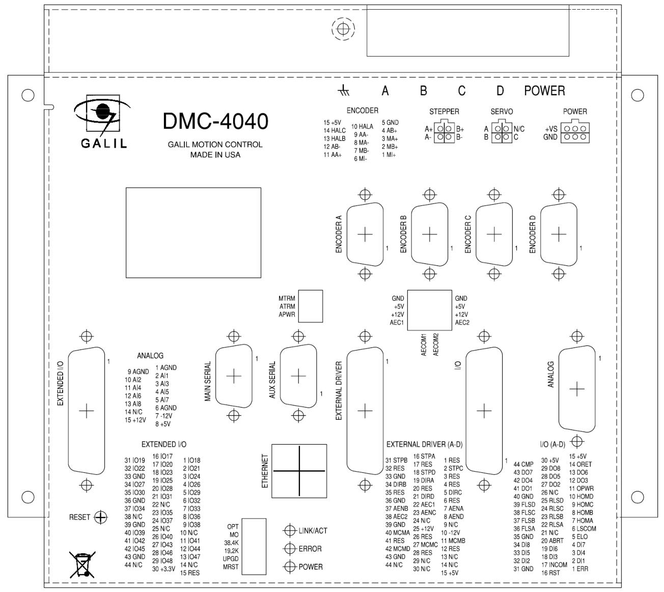
Layout and Size
Introduced the layout and size information of DMC-4040 and DMC-4080.
power connection
The power connector information for controllers without Galil amplifiers or when ordering ISCNTL power options, as well as the power connector information for controllers with Galil integrated amplifiers.
Required components
Including DMC-40×0 motion controller, motor amplifier (integrated when using Galil amplifier and driver), power supply for amplifier and controller, brushed or brushless servo motor or stepper motor with optical encoder, cable connected to DMC-40×0 integrated ICM, PC (RS232 or Ethernet for DMC-40×0), GalilTools or GalilTools Lite software package.
Installation steps
Determine the overall motor configuration, install jumpers on DMC-40×0, install communication software, connect 20-80VDC power supply to the controller, establish communication with Galil software, determine the axis for sine commutation, connect to amplifiers and encoders, connect standard servo motors/sine commutation motors/stepper motors, and adjust the servo system.
Hardware connection
Optical isolation input
Including limit switch input, origin switch input, abort input, ELO (electronic lock) input, reset input, and unconfirmed digital input, their functions, wiring, and electrical specifications are introduced.
TTL input
The auxiliary encoder input can be used for general purposes, with one auxiliary encoder per axis, containing two inputs, and can accept TTL level signals, etc.
High power optical isolation output
Introduced its electrical specifications and wiring methods, the outputs 9-16 of the 5-8 axis controller are located on the I/O (E-H) D-Sub connector.
analog input
There are eight analog inputs configured in the range of -10V to 10V, and different ranges and modes can be set through the AQ command. The electrical specifications are introduced.
TTL output
Including output comparison, error output, etc.
Expansion I/O of DMC-40×0 Controller
Provides 32 extended TTL I/O points that can be configured as inputs or outputs in 8-bit increments, and introduces their electrical specifications.
Amplifier interface
Introduced its electrical specifications and overview, as well as the ICM-42000 and ICM-42100 amplifier enable circuits, and the ICM-42200 amplifier enable circuit.
Software tools and communication
RS232 and RS422 ports
Introduced RS-232 and RS-422 configurations, including pin descriptions, configuration methods, baud rate selection, and handshake.
Ethernet configuration
Supports two industry standard protocols, TCP/IP and UDP/IP, and introduces addressing methods including MAC address, IP address, and UDP or TCP port number.
communication protocol
Introduced communication methods with multiple devices and multicast functionality.
Third party software usage
Supports tools such as DHCP, ARP, BOOT-P, and Ping for establishing Ethernet connections, and can communicate with hosts through any application that can send TCP/IP or UDP/IP packets, such as Telnet.
Modbus
An RS-485 protocol is introduced, including its function code, communication level, and examples.
data record
The status information block can be provided through QR commands, which introduces the mapping of data records and the interpretation of bit fields.
GalilTools (Windows and Linux)
It is a software toolset provided by Galil for the current Galil controller, which includes multiple tools and can run on both Windows and Linux platforms.
Create custom software interface
Provide programming tools such as GalilTools communication library, ActiveX Toolkit,. NET API, and DMCWin to facilitate users in developing their own custom software interfaces.
Command Fundamentals
introduce
Provide over 100 commands for specifying motion and machine parameters, which can be sent via ASCII or binary.
ASCII command syntax
The instruction consists of two uppercase letters followed by applicable arguments, terminated with a semicolon or carriage return, and introduces the syntax for specifying axis data and requesting actions.
Binary Command Syntax (Advanced)
The binary communication mode is about 20% faster than ASCII commands. The binary format can only send commands from a PC and cannot be embedded in applications. This article introduces the binary command format and tables.
Controller’s response to data
Return ‘:’ for valid commands and ‘?’ for invalid commands, error codes can be requested through the TC1 command.
Inquire about the controller
There is a set of commands that directly query the controller and return the required data, introducing the query commands and operands.
Sports programming
overview
Provides multiple motion modes, such as independent positioning and jogging, coordinated motion, electronic cam motion, and electronic gear transmission, and introduces application examples applicable to different modes.
Independent axis positioning
Each axis moves independently and follows its own contour. Relevant commands and operands, as well as examples, are introduced.
Independent Jogging
The ability to change speed, direction, and acceleration during motion is introduced, along with relevant commands and operands, as well as examples.
Position Tracking
This article introduces the characteristics and examples of a target that allows absolute position movement to be changed during motion.
Linear interpolation mode
Multi axis motion coordination, maintaining specified vector velocity, acceleration, and deceleration along a specified path, introducing relevant commands and operands, as well as examples.
Vector mode: Linear and circular interpolation motion
Allow the specification of long 2-D paths consisting of linear and circular arc segments, introduce relevant commands and operands, and provide examples.
Electronic gear transmission
Up to 8 axes can be connected to certain main axis electronic gears, and relevant commands and examples are introduced, including bevel gear transmission.
Electronic cam
A motion control mode that supports periodic synchronization of multiple motion axes, introducing relevant commands and examples.
PVT mode
Allowing the definition of arbitrary motion contours for all 8 axes through position, velocity, and time, relevant commands and examples are introduced.
Multi axis coordinated motion
Many applications require multiple axes to move in a coordinated manner, while also requiring smooth motion. An example was introduced.
contour mode
Allowing the specification of curves at any position for 1 to 8 axes, introduces relevant commands and examples, including recording and playback functions.
Stepper motor operation
Introduced the relevant commands for operating stepper motors, smoothing functions, methods for using encoders, and the Stepper Position Maintenance Mode (SPM).
Double loop (auxiliary encoder)
Except for the shaft configured for stepper motor operation and the shaft used for circular comparison, each shaft provides a second encoder interface, and its purpose and related commands are introduced.
**Backlash compensation**
Two methods of using auxiliary encoders for backlight compensation were introduced: continuous dual loop and sampling dual loop.
Motion Smoothing
Smooth motion and reduced mechanical vibration of the system can be achieved through IT and KS commands.
zeroing
The Find Edge (FE) and Home (HM) commands can be used to zero the motor to the mechanical reference point, and the steps and related commands for zeroing are introduced.
High speed position capture (latch function)
The position of the main encoder or auxiliary encoder can be captured within 25 microseconds of external low input signals (or index pulses), and its usage steps and examples are introduced.
Quick update rate mode
It can run at a much faster servo update rate than the default per millisecond, and introduces the update rates and related limitations of different models of controllers.
Application Programming
overview
Provide a powerful programming language that allows users to customize controllers for specific applications. The program can be downloaded to DMC-40×0 memory, freeing up the host for other tasks.
Using DMC-40×0 editor to input program
The GalilTools package or the line editor provided by DMC-40×0 can be used to input and modify programs, and the editing mode commands are introduced.
Program Format
Composed of DMC instructions, action instructions are combined with program flow instructions to form a complete program, introducing the use of tags and special tags.
Comment
You can use the NO command or apostrophe (‘) to add comments to the program.
Executing Programs – Multitasking
Up to 8 independent programs (threads) can run simultaneously, and instructions for starting and stopping threads are introduced.
debugger
Provide commands and operands that help debug applications, such as trace commands, error code commands, stop code commands, etc.
Program flow command
Including event triggers and conditional jumps, the program flow can be changed based on the occurrence of events.
Mathematics and Function Expressions
Provides a variety of mathematical operators and functions that can be used for data manipulation.
variable
Provides 510 variables that can be used to store mutable parameters, and introduces the definition and assignment of programmable variables.
array
Used for storing and collecting numerical data, this article introduces the definition, assignment, upload and download of arrays, as well as automatic data capture functions.
Data input (numerical and string)
The IN command can be used to prompt the user to enter numerical or string data, introducing the operator data input mode and the use of communication interruption.
Data output (numerical and string)
MG commands can be used to output numerical and string data, introducing message sending, port specification, and formatting.
Hardware I/O
Introduced the usage methods of digital output, digital input, auxiliary encoder input, input interrupt function, analog input, and extended I/O.
Example application
Examples include line cutters, X-Y worktable controllers, speed control through joysticks, position control through joysticks, and backlight compensation through sampling dual loops.
Hardware and software protection
overview
Providing multiple hardware and software functions to check for error conditions and disable motors in case of errors helps protect various system components from damage.
hardware protection
Including output protection lines (such as amplifier enable, error output) and input protection lines (such as universal stop, selective stop, ELO, forward limit switch, reverse limit switch).
software protection
Provides programmable error limits that can set limit values for position errors, introduces programmable position limits, Off On Error functionality, automatic error programs, and limit switch programs.
Troubleshooting
overview
Potential issues are classified into three categories: installation, stability and compensation, and operation. Various symptoms, diagnoses, causes, and remedial measures are introduced.
Operational theory
overview
Discussing the operation of a motion control system, a typical motion control system consists of multiple elements, and the operation can be divided into three levels: closed-loop, motion contour, and motion programming.
Closed loop system operation
Qualitatively and quantitatively explained the operation of the servo system, including the principle of closed-loop control, the causes of instability, and the role of PID filters.
system modeling
Established mathematical models for various elements of the servo system, such as motor amplifier, encoder DAC、 Digital filters and ZOH.
system analysis
Starting from the block diagram model of system elements, analyze to determine the stability of the system.
System design and compensation
Aiming to close the loop with cross frequency and phase margin, the analysis and design methods are introduced.
appendix
Electrical specifications
Electrical specifications including servo control, stepper control, input/output, and power requirements.
Performance specifications
Including performance parameters such as minimum servo loop update time, position accuracy, and speed accuracy.
Quick update rate mode
Introduced the update rate and disabled features in fast mode.
Ordering options for DMC-40×0
Introduced controller board options, CMB communication board options, ICM interconnect board options, and AMP internal amplifier options.
DMC-40×0 power connector
Introduced the Molex connector models and cable connections used.
Integration Components
Detailed descriptions, electrical specifications, mating connectors, and operation information of integrated components such as A1 to A8 were provided.