Call us 24/7uaedcs@163.com
Welcome to the official website of CNIACS Automation Technology Co., Ltd!
Call us 24/7uaedcs@163.com

ABB 1SVR011718R2500 Analog Signal Converter

Product overview

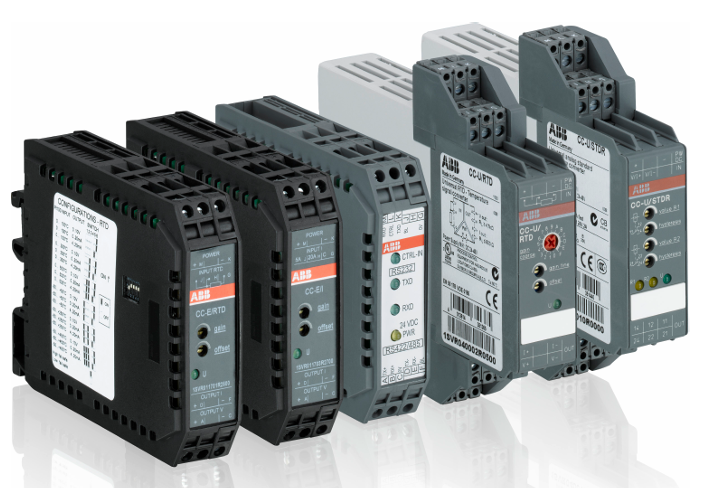
The ABB 1SVR011718R2500 analog signal converter belongs to the CC-E/STD series and is widely used in industrial automation, building automation, and process control fields for the processing and conversion of analog signals.

ABB analog signal converters include two series, CC-E and CC-U, which are mainly used for the conversion, measurement, amplification, filtering, and isolation of analog signals in industrial processes. They solve compatibility, interference, grounding loops, and other problems in signal transmission, ensuring accurate reception and processing of signals by control systems.

CC-E series

(1) Product features and advantages

Contains both general configuration devices and single function devices, with adjustment and operation components located on the front.

Equipped with electrical three-way isolation to ensure safe operation, with clear and distinct identification of wiring terminals.

Single function devices do not require adjustment or balancing; General equipment can configure input and output ranges through the DIP switch on the side, and the potentiometer on the front can adjust gain and offset by ± 5%.

(2) Main types and functions

Standard signal converter (CC-E/STD, etc.): processes the conversion of standard signals (0-5V, 0-10V, 0-20mA, 4-20mA, etc.) to achieve various conversions such as voltage voltage, voltage current, current voltage, and current current.

Thermal Resistance Converter (CC-E/RTD): It converts the temperature signal of PT100 thermal resistance, supports 2-wire or 3-wire connection, and outputs multiple standard signals.

Thermocouple Converter (CC-E/TC): processes J-type and K-type thermocouple signals, with cold junction compensation function, and outputs standard signals.

Current measurement converter (CC-E/I, etc.): measures AC/DC current signals from 0-5A and 0-20A and converts them into standard signals; CC-E IAC/ILPO does not require an auxiliary power supply and is used for sinusoidal current measurement.

Circuit power supply current isolator (CC-E I/I-1/2): realizes electrical isolation of current signals, with an internal voltage drop of ≤ 2.5V, and has 1 or 2 independent channels.

(3) Technical parameters

Power supply: 24V DC or 110-240V AC, typical power consumption is 1.5W/1.5VA.

Working temperature: 0…+60 ° C, storage temperature: -20…+80 ° C.

Accuracy: ± 0.5% full scale (some types), response time varies depending on the type, such as standard signal conversion of about 200 µ s and temperature signal conversion of about 10ms.

Protection level IP20, compliant with multiple standards and directives (EN 50178, Low Voltage Directive, etc.).

CC-U series

(1) Product features and advantages

One device can provide 8 different standard signal outputs, and both input and output sides can be configured universally. Some models come with 2 threshold relay outputs.

The regulating and operating components are located on the front, with electrical three-way isolation, using plug-in terminal blocks, and clearly labeled.

All devices can be configured with the required input and output range through the DIP switch on the side. The wide input range of the gain and offset stages makes signal conversion more flexible, and there are DC or AC (50/60Hz) power supply versions available.

(2) Main types and functions

Universal Signal Converter (CC-U/STD): Supports over 120 configurations and can configure the output response when the input signal is interrupted. The output signal has short-circuit protection.

Thermal resistance converter (CC-U/RTD): suitable for PT10, PT100, PT1000 and other thermal resistors, supporting 2-wire or 3-wire connections.

Thermocouple Converter (CC-U/TC): Processing signals from various types of thermocouples (K, J, T, S, etc.), capable of temperature difference measurement, with optional cold end compensation.

Voltage measurement converter (CC-U/V): measures true RMS (TRMS) from 0-600V, suitable for voltage signals of various waveforms.

Signal converters with relay outputs (CC-U/SDDR, CC-U/TCR): CC-U/SDDR processes standard signals, CC-U/TCR processes thermocouple signals, both with two threshold relay outputs, and the threshold and hysteresis can be independently adjusted.

Current measurement converter (CC-U/I): measures true RMS current signals of 0-1A and 0-5A, suitable for various waveforms.

Technical Parameter

Physical parameters

Size: 75mm high x 22.5mm wide x 107mm deep, compact in size and structure, easy to install in various control cabinets, saving space.

Weight: Approximately 99.875g (0.084kg or 0.22lbs), lightweight, easy to transport and install.

Protection level: IP20, capable of preventing solid foreign objects with a diameter greater than 12.5mm from entering, and can be used in general industrial environments.

Installation method: Standard DIN rail installation, convenient and fast, easy to install and layout in industrial control cabinets.

Environmental parameters

Working temperature range: -20 ° C to+60 ° C (some sources mention up to -40 ° C to+85 ° C or 0…+60 ° C), can adapt to industrial environments with certain temperature changes, but exceeding this range may affect equipment performance and lifespan.

Storage temperature range: -20…+80 ° C. Storing devices within this temperature range ensures stable performance and prevents damage due to temperature issues.

Relative humidity: 5% -95% RH (no condensation), with certain requirements for the humidity of the usage environment. Avoid using in high humidity and easily condensing environments to prevent affecting the electrical performance and service life of the equipment.

Other

Isolation design: It has 3 electrical isolation channels, which can effectively isolate input and output signals, prevent interference, and improve the safety and stability of the system.

Standard compliance: Compliant with RoHS, UL 61010-1, UL 61010-2-201, CE and other standards to ensure product quality and safety.

ABB BC810K02 CEX Bus Interconnection Unit Kit

Product overview

BC810K02 is a CEX Bus interconnect unit kit launched by ABB, mainly composed of BC810 interconnect unit, TP857 base board, TK851 interconnect cable, and TB850 CEX Bus terminator, used to enhance the availability of CEX Bus. Its core function is to divide CEX Bus into independent sections, support redundant communication interface units, enhance the stability of the system under redundant communication interface configuration, and be suitable for industrial automation systems that require high availability.

Composite and structure

Core components: The kit includes 2 BC810 interconnect units, 2 60mm wide TP857 base plates, 1 1.0-meter-long TK851 interconnect cable, and 2 TB850 CEX Bus terminators.

BC810 unit structure: consisting of a base board (TP857) and a power/logic board.

Base board: Integrated with CEX Bus connector and external power interface, grounded to DIN rail through shell metal components, and carrying voting diodes and fuses for external power supply.

Power/Logic Board: Includes+3.3V converter, logic circuit, CEX Bus interconnect driver, and interconnect cable connectors.

Compatibility and system characteristics

Compatible with CPU modules: Can be used in conjunction with CPU modules such as PM857, PM861A, PM862, PM863, PM864A, PM865, PM866, PM866A, PM867, and PM891.

Redundancy support: Supports redundant system configuration, enabling online replacement of CPU base boards without interfering with CEX communication in fully redundant systems with dual BC810 interconnection and equipped with primary/backup CPU pairs; But when replacing BC810, the communication of the connected CEX section will be suspended.

CEX Bus function: Used to expand onboard communication ports to connect communication interface units, supports redundant communication interfaces, and improves bus availability by partitioning.

Key features and advantages

Support redundant communication interface units to enhance system communication reliability.

Allow online CPU replacement to ensure continuous system operation.

Powered by an external power source, stable and reliable.

Support hot swapping for easy maintenance and component replacement.

​Technical Parameter

Product Code 3BSE031155R1 (BC810K02)

Redundancy capability: support

High integrity: support

Power consumption: typical 50mA at+24V voltage, maximum 70mA; typical power consumption 1.2W

Power input: 24V DC (allowable range 19.2-30V DC)

Working temperature:+5 to+55 ° C (+41 to+131 ° F)

Storage temperature: -40 to+70 ° C (-40 to+158 ° F)

Relative humidity: 5% -95% (without condensation)

Protection level: IP20 (compliant with EN60529, IEC 529)

Certification of CE mark; Electrical safety complies with UL 61010-1 and UL 61010-2-201; Certification for hazardous locations: cULus Class 1, Zone 2, etc; Ship certification ABS, BV, DNV-GL, LR; Compliant with RoHS (EN 50581:2012) and WEEE (Directive/2012/19/EU) standards

Dimensions: Width 59mm (2.9 inches), Height 185mm (7.3 inches), Depth 127.5mm (5.0 inches)

Weight (including base): 1.5kg (3.31 pounds)

Working principle

Hardware collaboration principle: It consists of a base board (TP857) and a power/logic board. The base board is responsible for connecting the CEX Bus and external power supply, and is grounded through the metal components of the housing to ensure electrical safety. It also carries the voting diode and fuse of the external power supply, and performs preliminary treatment on the power supply. The power/logic board converts external power to+3.3V for internal use, while its logic circuit and CEX Bus interconnect driver are responsible for data processing and transmission, and interacts with other devices through interconnect cable connectors.

System communication principle: In industrial automation systems, CEX Bus is used to expand onboard communication ports. BC810K02 reduces communication interference between different devices and improves communication efficiency and reliability by dividing CEX Bus into separate sections. In a fully redundant system, two interconnected BC810s work with primary/backup CPUs, supporting online replacement of CPU base boards without interfering with CEX traffic and maintaining stable system communication; But when replacing BC810 itself, the communication of the connected CEX section will temporarily stop. In addition, it supports redundant communication interface units. When a communication interface fails, the redundant interface can take over the work in a timely manner, ensuring uninterrupted data transmission and improving the availability of the entire system.

ABB RELION ®  615 series REU615 voltage protection

Product overview

REU615 is ABB RELION ®  There are two standard configurations (A and B) for voltage protection and control relays in the 615 series. Configuration A is applicable to voltage and frequency based protection schemes in power systems and distribution systems, including networks with distributed generation; Configuration B is specifically designed for automatic voltage regulation of power transformers equipped with on load tap changers. Both configurations have additional functions such as circuit breaker control, measurement, and monitoring, and adopt a compact withdrawable unit design, fully utilizing the potential of IEC 61850 standard in communication and interoperability between substation automation equipment.

Core functions and features

Protection function

Voltage protection: including three-phase overvoltage protection (3U>), three-phase undervoltage protection (3U<), residual overvoltage protection (Uo>), positive sequence undervoltage protection (U1<), negative sequence overvoltage protection (U2>), etc., which can cope with different voltage abnormal situations.

Frequency protection: It has over/under frequency (f>/f<) and frequency change rate (df/dt) protection functions to prevent damage to network components caused by abnormal system frequency.

Overcurrent protection: Configuration B includes three-phase non directional overcurrent protection (low, high, instantaneous stages) for detecting overcurrent and short circuit faults.

Thermal overload protection: Configure B’s three-phase thermal overload protection (with two time constants) to monitor the thermal stress of the transformer winding and prevent premature aging of the winding insulation.

Other protections include arc protection (optional configuration A), multi-purpose protection, and other functions.

Control function: Supports circuit breaker control, isolation switch control, grounding switch control, on load tap changer control, etc., which can achieve effective control and interlocking of primary equipment.

Measurement function: It can measure various electrical parameters such as three-phase current, voltage, residual current, residual voltage, sequence current, sequence voltage, power, energy, frequency, etc. It can also perform RTD/mA measurement (configuration B is optional).

Data recording and event recording

Disturbance recorder: capable of recording analog and digital channel data, with sampling frequency varying depending on the rated frequency, adjustable recording length, and diverse triggering methods.

Fault record: Record fault related data for easy fault analysis and diagnosis.

Load curve recording: The load history of the corresponding feeder can be observed.

Communication function: Supports multiple communication protocols, including IEC 61850 (supporting Edition 2), IEC 61850-9-2 LE (process bus) IEC 60870-5-103、Modbus ®、 DNP3, etc., have Ethernet redundancy (HSR, PRP), self-healing Ethernet ring and other functions, which can achieve secure communication.

Human Computer Interaction: Equipped with Local HMI (LHMI) and Web HMI (WHMI), LHMI includes a display screen, LED indicator lights, and keyboard for easy local settings, monitoring, and control; WHMI can securely access relays through a web browser.

Authorization and Audit Tracking: Four predefined user categories (VIEWER, OPEROTOR, ENGINEER, and ADMINIST) are defined, each with different permissions; Equipped with audit tracking function to record critical systems and security related events.

Standard configuration

Configuration A

Application scenario: It is applicable to voltage protection and synchronization check in the medium voltage network. It can handle the fault caused by abnormal voltage in the power system, and can handle the synchronization and power on check of two galvanically interconnected networks.

Main functions: including voltage protection (overvoltage, undervoltage, residual voltage, sequence voltage, etc.), frequency protection, load shedding and recovery, arc protection (optional), synchronous inspection, as well as control functions such as circuit breakers, isolation switches, grounding switches, etc.

Configuration B

Application scenario: Used for automatic voltage regulation of power transformers equipped with on load tap changers, including three-phase non directional overcurrent protection, three-phase undervoltage and overvoltage protection, etc.

Main functions: In addition to voltage protection, overcurrent protection, thermal overload protection, etc., it also has functions such as on load tap changer control and voltage regulation, tap changer position indication, etc. The optional RTD/mA input module is used for temperature measurement, etc.

Technical parameters and requirements

1、 Requirements for measuring transformers

(1) Current Transformer (CT)

Requirements for CT for overcurrent protection

Accuracy level and accuracy limit coefficient: The accuracy level of current transformers used for protection is usually represented by “P” (meaning protection), followed by the number indicating the maximum allowable composite error at the rated accuracy limit current. For example, 5P10 represents an accuracy level of 5P and an accuracy limit coefficient of 10. Both 5P and 10P levels are suitable for non directional overcurrent protection, with 5P level having higher accuracy.

Actual accuracy limit coefficient calculation: The actual accuracy limit coefficient (F a) is related to the rated accuracy limit coefficient (F n), CT rated load (S n), CT internal secondary load (S in), and actual external load (S). The calculation formula is:

F a ≈ F n × ∣ S n+S ∣∣ S in+S n ∣ CT selection principle: For non directional overcurrent protection, it is recommended to choose a CT with an actual accuracy limit factor of at least 20. The rated primary current (I 1n) of the CT should meet the requirement of I 1n>I kmax/100 (I kmax is the maximum fault current) to avoid exceeding the thermal and dynamic intensity of the input current measurement of the protective relay.

Suggestion for starting current setting: If I kmin is the lowest current that should be activated during the highest set overcurrent stage, the starting current should be set to:

The current starting value, with a coefficient of 0.7, takes into account protection relay error, CT error, and short-circuit calculation deviation.

2、 Input parameters

(1) Incentive input

Phase current (configuration B)

Terminals: X120:7-8 (IL1), X120:9-10 (IL2), X120:11-12 (IL3)

Can be used for single-phase or two-phase applications, where some excitation inputs can be left vacant, but at least X120:7-8 needs to be connected

Residual current (configuration B)

Terminal: X120:13-14 (Io)

Phase voltage (configuration B)

Terminals: X120:1-2 (U1), X120:3-4 (U2), X120:5-6 (U3)

Phase voltage (configuration A)

Terminals: X130:11-12 (U1), X130:13-14 (U2), X130:15-16 (U3)

SECRSYN1 reference voltage (configuration A)

Terminal: X130:9-10 (U12B)

Residual voltage (configuration A)

Terminal: X130:17-18 (Uo)

(2) RTD/mA input (configuration B optional)

Terminals and corresponding functions:

X130:1-2:mA1(AI1)

X130:3-4:mA2(AI2)

X130:5-6:RTD1(AI3)

X130:7-8:RTD2(AI4)

X130:9-10:RTD3(AI5)

X130:11: RTD channels 1-3 common ground

X130:12: RTD channels 4-6 common ground

X130:13-14:RTD4(AI6)

X130:15-16:RTD5(AI7)

X130:17-18:RTD6(AI8)

ABB Symphony Harmony/INFI 90 DCS Remote I/O Module

Overview of Upgrade Kit

ABB has launched a remote I/O module upgrade kit for the Symphony Harmony/INFI 90 process control system, which includes a new low-cost IMRIO22 module aimed at providing continuous lifecycle support for the system and addressing various issues with existing systems.

Solve the problem

Components are outdated and new parts are no longer available.

The cost of replacing parts is high.

The ability to repair parts has decreased.

The electrical remote communication chain is affected by noise and lightning strikes.

Difficult to troubleshoot remote I/O issues.

Slow link speed and time-consuming I/O point updates.

Controller configuration requires the use of multiple segment control blocks for special “adjustments”.

IMRIO02 has firmware compatibility issues with some I/O modules.

Be extra cautious when replacing system components.

Advantages of the plan

Reliability improvement: Updated technology has been adopted to enhance fiber optic communication.

Spare parts availability: Provide new replacement parts.

Easy to replace: Compatible with existing remote I/O settings, with the same rack size, can use existing fiber optic cables, IMRIO22 replaces IMRIO02 in remote cabinets.

Reduce cabinet space occupation: IMRIO02 in the local cabinet is no longer needed, and its functions are integrated into BRC300/400, replacing the existing MFP or MFC controllers in the local cabinet with BRC.

Control performance improvement: increased memory capacity, faster execution and communication speed.

Improved communication link and remote I/O update speed.

Hardware/firmware compatibility improvement: better compatibility between remote I/O processors and remote I/O modules.

Easy firmware upgrade: The IMRIO22 module has flash memory.

Redundancy enhancement: Faster fault detection/switching speed from primary IMRIO22 to backup IMRIO22.

Error checking and diagnostic improvement: facilitates troubleshooting.

Redundant HNET remote communication channel.

Minimum System Requirements

The BRC300/400 controller requires a Process Bus Adapter (PBA), which needs to be added if it is not present.

Composer engineering tool version 5.0 or higher.

Fiber optic cable (62.5/125 micron multimode) for remote links.

Restrictive conditions

Only supports fiber optic point-to-point communication links.

The electrical link (dual axis or coaxial cable) must be replaced with optical fiber.

Serial or Daisy Chain multi-point links are not supported, and multi-point connections for multiple remote cabinets (up to 6) now require a star configuration from the local cabinet.

Upgrade package content

Non redundant configuration: Part number INRIOK01

Redundant configuration: Part number INRIOK02

Harmony remote I/O module: 1, 2 IMRIO22

Process bus adapter: 1, 2 PHCBRCPBA20000

HNET fiber optic repeater terminal unit: 4, 4 NTRL04

HNET’s process bus adapter cable: 2, 2 PMKHRMPBA1T004

HNET Bus Terminators: 4, 4 PHAMSCTER30000

Redundant cables for bridge controller: 0, 1 PMKHRMBRC3000A

Note: The multi-point remote I/O architecture will require inter column connection cables to daisy chain additional terminal units in the local cabinet.

System/application compatibility

The remote I/O function is compatible with all other existing functions of the Harmony BRC300/400 or higher version controller, including but not limited to:

Supports multiple remote I/O links.

Supports mixed I/O types, such as IOR/S800, Harmony rack I/O, and Harmony module I/O.

Existing fiber optic remote link cables can be reused.

ABB Ability™ Symphony® Plus HR Series Control and I/O - Symphony Plus

ABB REM610C55HCNN02 motor protection relay

ABB REM610C55HCNN02 belongs to the REM610 series motor protection relay, which is widely used in the industrial field. It is specially designed for the protection of medium and large asynchronous motors, which can effectively ensure the safe and stable operation of motors. It can also be used for the protection of equipment such as feeding cables and power transformers

Core functions

Protection function

Thermal overload protection: detects short-term and long-term overload, calculates thermal stress based on the square value of the motor’s thermal capacity and load current, and can set parameters such as safe stalling time, weighting coefficient, time constant multiplier, etc.

Start monitoring: It can be based on thermal stress calculation or timed overcurrent protection to prevent damage to the motor during the starting process due to overload or short circuit faults.

Short circuit protection: detects overcurrent caused by phase to phase, winding to winding, and phase to ground short circuits, with instantaneous or timed characteristics.

Undercurrent protection: detects faults such as load loss, suitable for applications where undercurrent is considered a fault.

Ground fault protection: detects phase to ground current, has timing characteristics, and can be set to instantaneous action.

Unbalance protection: Based on negative sequence current detection of phase imbalance, it prevents rotor overheating.

Phase sequence protection: detects motor reverse rotation caused by phase sequence errors.

Accumulated startup time counter: prevents motor overheating caused by too frequent startup attempts.

Circuit breaker fault protection: detects the situation where the circuit breaker should have acted but did not.

Temperature protection (optional): Detect the temperature of motor bearings and windings through RTD sensors or thermistors.

Measurement function: It can measure various parameters such as phase current, zero sequence current, negative sequence current, thermal level, start-up time, cumulative start-up time, restart suppression time, motor running time, etc.

Control function: Supports local and remote control of switchgear, including opening and closing operations of circuit breakers and isolating switches, with interlocking function to prevent misoperation.\

ABB REM611 Motor Protection & Control Relay at ₹ 50000 | Industrial ...

Data recording and event recording

Disturbance recorder: It can record data from 4 analog channels and up to 8 user selectable digital channels. The sampling frequency varies according to the rated frequency, the recording length can be adjusted, and there are various triggering methods.

Event recording: Up to 100 event codes and timestamps can be recorded, including events such as startup and tripping during the protection phase.

Communication function: Equipped with front optical communication port (infrared) and optional rear communication module, supporting communication protocols such as SPA bus, IEC 60870-5-103, Modbus (RTU and ASCII), etc.

​Technical Parameter

Power supply: Supports multiple AC and DC auxiliary voltages, with different power consumption in static and operating states, and a maximum ripple of 12% of the DC value.

Input

Current input: rated frequency 50/60Hz, rated current 1A or 5A, with certain thermal and dynamic current tolerance capabilities.

Digital input: Supports multiple voltage levels, activation threshold and operating range vary depending on the model, with low current and power consumption.

Output

Signal output: Rated voltage 250V AC/DC, with certain continuous carrying capacity, short-term carrying capacity, and breaking capacity.

Power output: Parameters are similar to signal output and are suitable for controlling devices such as circuit breakers.

Environmental conditions: The recommended continuous operating temperature range is -10…+55 ° C, the extreme temperature range (short-term) is -40…+70 ° C, the storage and transportation temperature range is -40…+85 ° C, and the humidity is less than 95% RH.

Electromagnetic compatibility: Passed multiple electromagnetic compatibility tests, including 1MHz pulse interference, electrostatic discharge, radio frequency interference, etc.

Configuration and parameter settings

Setting group: Provides two optional setting groups that can be switched through HMI or serial communication, including parameters such as safety stall time, weighting coefficient, startup values and operation time for various protection stages.

Switch group: including SGF, SGB, SGR, SGL and other switch groups, used to configure the functions of relays, digital inputs, signal routing of output contacts, and LED indications.

Parameterization: External parameterization can be performed through HMI or using Relay Setting Tool, with set values within a specified range and some parameters requiring password protection.

Installation steps

1、 Preparation before installation

Environmental inspection: Ensure that the installation location meets environmental requirements, with a working temperature range of -10…+55 ° C, relative humidity<95% (no condensation), and avoid harsh environments such as severe vibration, dust, corrosive gases, etc.

Preparation of Tools and Materials: Prepare suitable tools such as screwdrivers, wire strippers, and crimping tools, as well as wires that meet specifications (selected according to terminal requirements, such as terminal X2.1 for 0.5… 6.0mm ² wires, X3.1 and X4.1 for 0.2… 2.5mm ² wires), wiring terminals, and other materials.

Equipment inspection: Open the box and check if the appearance of the relay is intact, verify if the model (REM610C55HCNN02) and accessories are complete, including installation brackets, instructions, etc.

2、 Mechanical installation

Choose installation method: Select the installation method according to actual needs, supporting semi embedded installation, wall mounted installation, 19 “rack installation, etc. Corresponding installation kits can be used (such as semi embedded installation kit 1MRS050696, 19” rack installation kit 1MRS050695, etc.).

Fixed equipment:

If it is a rack installation, place the relay smoothly into the corresponding position of the 19 “rack, fix it on the rack with screws, and ensure that the installation is firm and not loose.

If it is wall mounted or embedded installation, use expansion screws or fixing screws to fix the installation bracket to the wall or cabinet according to the size of the installation hole, and then fix the relay to the bracket.

3、Electrical connection

(1) Power connection

Find the power terminal at the back of the relay (X4.1-1 is “+”, X4.1-2 is “-“).

According to the rated auxiliary voltage indicated on the relay (this model is 100-240V AC/110-250V DC), connect the corresponding power supply wires to ensure correct positive and negative polarity.

The stripping length of the wire is moderate (about 5-8mm), and after inserting the terminal, tighten the screw to ensure good contact without looseness or virtual connection.

(2) Current input connection

Phase current connection: Connect the secondary side of the current transformer (CT) to the phase current input terminal. The specific terminal definitions are as follows:

X2.1-1/2: Connect L1 phase current

X2.1-3/4: Connect L2 phase current

X2.1-5/6: Connect L3 phase current

Grounding fault current connection: According to the CT type (which has a grounding fault current input of 5A), connect the grounding fault current circuit to terminals X2.1-7/8.

Ensure correct polarity of CT wiring to avoid phase errors affecting protection function.

(3) Digital input connection

The digital input terminals are located at X4.1 and X3.1 (when RTD module is optional), as follows:

X4.1-23/24: Connect DI1

X4.1-21/22: Connect DI2

If equipped with RTD modules, X3.1-1/2, X3.1-3/4, and X3.1-5/6 are respectively connected to DI3, DI4, and DI5

According to the rated voltage of the digital input (this model is 110/125/220/250V DC), connect the external control signal wire, pay attention to wire insulation, and avoid short circuits.

(4) Output contact connection

Power output (PO) and signal output (SO):

PO1(X4.1-16)、PO2(X4.1-14)、PO3(X4.1-12/13) For power output, used to control devices such as circuit breakers, connected to external circuits according to control requirements.

SO1(X4.1-9/10/11)、SO2(X4.1-6/7/8) For signal output, used for alarm or status indication, connected to indicator lights, alarms, etc.

IRF contacts: X4.1-3 (common terminal), X4.1-4 (closed when faulty), X4.1-5 (closed when normal), connected to the fault alarm circuit.

Le nouveau relais de protection tout-en-un REX610 d'ABB offre une ...

ABB TU810V1 Compact Terminal Unit

Product overview

TU810V1 is a 16 channel 50V compact module terminal unit (MTU) designed by ABB for the S800 I/O series. It is a passive device mainly used to connect field wiring to I/O modules, and also includes some Module Bus components. Its function includes allocating Modulus Bus to the I/O module and the next MTU, and generating the correct address for the I/O module by shifting the output position signal to the next MTU.

Core Features and Advantages

Adopting a single wire connection to achieve compact installation of I/O modules.

Supports up to 16 on-site signals and process power connections.

Can be connected to Modulus Bus and I/O modules.

Equipped with mechanical key control devices to prevent incorrect insertion of I/O modules.

Equipped with DIN rail locking device for grounding, supporting DIN rail installation.

Basic parameters

Product Code: 3BSE013230R1

Type: Compact

Connection method: Terminal block

Number of channels: 16

Voltage: 50V

Installation direction: Both directions are available

Installation temperature: Horizontal installation at 55 ° C (131 ° F), vertical installation at 40 ° C (104 ° F)

Compatible with I/O modules: AI810, AI815 and other models (such as AI, AO, DI, DO, DP series related modules)

Process connection: 2 × 2 process power supply, 5 × 2 process power supply (0V)

​I/O redundancy type: single redundancy

Environment and Certification

Compliant with CE mark, electrical safety follows standards such as EN 61010-1, UL 61010-1, etc.

Dangerous Place Certification: C1 Div 2 cULus, C1 Zone 2 cULus, ATEX Zone 2.

Ship certification: ABS, BV, DNV-GL, LR.

Working temperature: 0 to+55 ° C (+32 to+131 ° F), certified temperature range:+5 to+55 ° C; Storage temperature: -40 to+70 ° C (-40 to+158 ° F).

Pollution level: Level 2 (IEC 60664-1), anti-corrosion level: ISA-S71.04 G3.

Relative humidity: 5% to 95% (non condensing), protection level: IP20 (IEC 60529).

Compliant with RoHS (EN 50581:2012) and WEEE (Directive/2012/19/EU) standards.

Size and weight

Width: 64mm (2.52 inches) including connector, 58.5mm (2.3 inches) from edge to edge after installation.

Depth: 64mm (2.52 inches) including terminals.

Height: 170mm (6.7 inches) including lock buckle.

Weight: 0.17kg (0.37 pounds).

Application area 

Industrial Automation: Used for industrial production lines, automation equipment, etc., it is an important component of industrial automation systems that can achieve automated control of industrial processes, such as CNC machinery, electronic manufacturing, automotive manufacturing, and other industries.

Process control: Suitable for process control in industries such as chemical, metallurgical, food, petroleum and natural gas, it can control various parameters such as temperature, pressure, flow rate in industrial processes, and achieve precise measurement and control of process variables.

Discrete control: can be applied to discrete manufacturing industries, such as mechanical manufacturing, plastic machinery, etc., to control and manage discrete production processes.

Motion Control and Robotics: Plays a role in robot control, controlling the motion and operation of robots; It is also applicable to motion control scenarios, providing control support for related devices.

Electricity and Energy: Used in energy related fields such as electricity, water conservancy, water treatment/environmental protection, for data collection, equipment control, and system monitoring to ensure the stable operation of the energy system.

Other fields: It can also be used in industries such as building materials, paper printing, textile printing and dyeing, tobacco, as well as HVAC control and lighting control in building automation; It is also applicable to distributed control systems and SCADA systems, achieving centralized control of multiple devices and monitoring and management of processes.

ABB REF 541, REF 543, and REF 545 feeder terminals

Product overview

REF 541, REF 543, and REF 545 feeder terminals are equipment developed by ABB for the protection, control, measurement, and monitoring of medium voltage power grids, and are part of ABB’s substation automation system. They can adapt to different types of switchgear (such as single bus, double bus, and duplex systems) as well as multiple network types (such as neutral insulation networks, resonant grounding networks, and partial grounding networks), and can also be applied to the protection and control of medium-sized three-phase asynchronous motors and parallel capacitor banks for reactive power compensation. The main difference between these three devices lies in the number of digital inputs and outputs.

Core functions

Protection function

It includes multiple types of protection, such as non directional and directional overcurrent and ground fault protection, residual voltage protection, overvoltage and undervoltage protection, thermal overload protection, circuit breaker fault protection, and automatic reclosing.

The protection function based on current measurement can use Roche coils or traditional current transformers, while the protection function based on voltage measurement can use voltage dividers or voltage transformers.

control function 

Support local and remote control of switchgear, status indication of switchgear, and interlocking at interval and station levels.

Measurement function

Capable of measuring phase current, phase to phase and relative ground voltage, residual current and voltage, frequency, power factor, active and reactive power, and electrical energy.

The standard configuration includes pulse counter inputs, with varying quantities depending on the model (7 for REF 541 and 10 for REF 545).

Status monitoring function

Including circuit breaker status monitoring, trip circuit monitoring, and internal self-monitoring of feeder terminals.

Other functions

Such as synchronous inspection, frequency protection, capacitor bank protection and control, current and voltage harmonic measurement, etc.

Equipped with RTD/analog modules for temperature measurement, current/voltage measurement, and mA output.

Data recording and communication

Transient disturbance recorder: capable of recording 16 current or voltage waveforms and 16 logical digital signals, with a sampling frequency of 2kHz at rated frequency 50Hz and 2.4kHz at 60Hz. The recording can be uploaded and converted to COMTRADE format.

Communication: Provides two communication interfaces, one for local communication with PC and the other for remote communication through substation communication system, supporting SPA and LON serial communication protocols.

Software and hardware configuration

Hardware

Analog channels: Depending on whether sensors are included, there are 9 (no sensors) or 10 (with sensors) analog channels, as well as virtual channels for calculating neutral current and residual voltage.

Digital input: voltage controlled and optically isolated, partially programmable as a pulse counter, with a pulse counting frequency of up to 100Hz, and two global parameters for suppressing digital input oscillations.

Digital output: divided into high-speed power output (HSPO), power output (PO), and signal output (SO).

Display panel: equipped with a fixed display screen or external display module, the display panel includes multiple buttons and indicator lights for operating and indicating device status.

Software

It can be configured through the CAP 505 relay product engineering tool, including basic terminals, protection and logic function blocks, control and measurement functions, etc.

Support the use of relay configuration tools to program PLC functions (such as interlocking and alarm logic), using functional block diagram language.

ABB REF541EM115AAAA feeder terminal Reasonable price - SAUL ELECTRIC

Technical Parameter

Environmental conditions: The specified working temperature range is -10…+55 ° C, the transportation and storage temperature range is -40…+70 ° C, the front protection level of the shell is IP 54, and the back connection terminal is IP 20.

Power supply: There are two basic versions of power modules, PS1 and PS2, and the input voltage and operating range vary depending on the model.

Input and output parameters: including voltage, current range, and accuracy of digital input and output, analog input and output, etc..

Application scenarios

Suitable for various application scenarios of medium voltage power grids, such as different types of switchgear and networks, as well as protection, control, and monitoring of medium-sized three-phase asynchronous motors, parallel capacitor banks, etc. Specific application examples include utility incoming lines, feeders, measuring cabinets, ring/mesh network cable feeders, etc.

Major function 

Protection function: With multiple types of protection, it can comprehensively ensure the safety of the power system. In terms of current protection, overcurrent directional protection has 8 thresholds with freely programmable tripping characteristics, ground fault directional protection has 2 thresholds, and ground fault directional fan-shaped protection has 10 thresholds, which can accurately detect and respond to abnormal current situations. Voltage protection can monitor and protect the system voltage, preventing damage to equipment caused by overvoltage or undervoltage. It also covers differential protection, power direction protection, distance protection, etc., which can be used to protect multiple system components and provide reliable protection solutions for different types of faults. In addition, functions such as automatic reclosing, frequency monitoring, synchronization detection, and fault recording have further enhanced the stability and reliability of the system.

Control function: Supports multiple operating state switches, including running, testing, setting state switches, as well as local and remote state switches, making it convenient for operators to flexibly control equipment according to actual needs. Equipped with closing, opening and emergency opening functions, ensuring effective control of the equipment in different situations. Various interlocking functions are set up in the software, and the interlocking functions implemented through software settings can effectively prevent misoperation and ensure the safety of equipment and personnel.

Measurement function: It can accurately measure various electrical parameters, including three-phase current, zero sequence current, maximum demand for three-phase current, three-phase/line voltage, zero sequence voltage, active/reactive power, active/reactive electricity degree, power factor, frequency, etc. The measured values can be displayed on the LCD screen as numbers and LED bar charts, visually presenting the system’s operating status and providing accurate data reference for operators.

Communication function: Supports multiple communication protocols such as RS485, Modbus, IEC 61850, DNP3.0, etc., and can exchange data with different devices and systems. Adopting fiber optic connection, it has the characteristics of simple wiring, strong anti-interference ability, and high reliability, which can achieve real-time information processing and perfect system management, facilitate networking, and meet communication needs in different scenarios.

Monitoring and diagnostic functions: capable of effectively monitoring primary equipment, such as monitoring spring charging time (when applicable) and trip coils, to promptly identify potential equipment issues. Equipped with a self diagnostic program that can continuously check the status of hardware and software modules. The binary input and output module is equipped with watchdog contacts, which are triggered in the event of a fault or power outage. The analog input channel can be selected for monitoring, detecting disconnection from the instrument transformer or sensor connection, and triggering an alarm.

Power quality function: It can monitor and analyze the power quality of the power system, provide data support for optimizing power quality, and ensure that the power system provides high-quality power for various equipment.

PLC function: Standardize the wiring of switchgear, simplify production management, reduce the types of spare parts, and facilitate on-site management and operation maintenance. Through flexible software development, engineering design can be simplified, design cycles can be shortened, on-site debugging efficiency can be improved, and it is easy to change the function of the switchgear or adapt to different load properties in the future.

ABB 馈线终端 REF541 数字继电器 - 启明自动化

ABB UNITOL 1000 series automatic voltage regulator

Product overview

The ABB UNITOL 1000 series is a compact, high-performance automatic voltage regulator (AVR), consisting of three models: UNITOL 1005, 1010, and 1020, designed specifically for low-power range applications, setting a new benchmark in the industry with functionality, reliability, and connectivity. This series adopts separate communication and control processors, equipped with non-volatile flash storage for event and data logs, supports Ethernet time synchronization and event timestamps, and is suitable for various industrial scenarios.

Product model and core parameters

UNITROL 1005:5A continuous, 10A peak, for low-end excitation applications, shares software source code and simulation model with 1010/1020, supports USB, Ethernet, no HMI, analog I/O is 2 inputs, digital I/O is 8 inputs+4 outputs

UNITROL 1010:10A continuous, 20A peak, compact device with limited functionality, same mechanical size and interface as 1020, supports Ethernet RS485(Modbus RTU/VDC)、USB, Analog I/O consists of 3 inputs and 2 outputs, while digital I/O consists of 4 inputs and 8 inputs/outputs

UNITROL 1020:20A continuous, 38A peak, high performance, with a local human-machine interface, comprehensive functions, interface identical to 1010, I/O configuration identical to 1010, and an intuitive local control panel added

Main functions and features

Control mode: Supports automatic voltage regulator (AVR), excitation current regulator (FCR), power factor regulator (PF), reactive power regulator (VAR), etc., and can achieve disturbance free switching between various modes.

Limiter and protection: including excitation current limiter (minimum/maximum), PQ minimum limiter, motor current limiter, V/Hz limiter, motor voltage limiter, etc., to ensure the safe and stable operation of synchronous motors; It has functions such as soft start, voltage matching, and rotating diode monitoring.

Software Function Package: Provides four versions: ECO, LIGHT, BASIC, and FULL, ranging from basic functions to advanced features such as synchronization, event recording, data recording, and real-time clock. The FULL version can also add a Power System Stabilizer (PSS) option, which complies with the IEEE 421.5-2005 standard.

Communication capability: Supports protocols such as Modbus RTU, Modbus TCP, CAN, etc., equipped with Ethernet and USB ports for easy connection to debugging tools and remote access.

Environmental adaptability: Designed for wide temperature environments and harsh industrial conditions, it can be directly installed on machines and has high EMC immunity.

Debugging and maintenance tools

CMT 1000 is a debugging and maintenance tool for this series, which connects devices via USB or Ethernet. Its functions include:

Set parameters and adjust PID to ensure stable operation;

Comprehensive monitoring system to assist in identifying and locating issues during on-site debugging;

Provide functions such as a main window (displaying access modes and device information), a settings adjustment window (viewing control modes, alarms, etc.), and an oscilloscope (recording and analyzing signals).

application area 

Widely used in land-based power plants (based on diesel engines, gas/steam turbines, water turbines), ships (electric propulsion and auxiliary power supply), traction (diesel electric locomotives), wind energy (based on directly connected synchronous motors), synchronous motors, and variable speed applications.

Working principle

Signal acquisition: Real time acquisition of key parameters such as three-phase voltage, current, and grid voltage of the motor through measuring terminals, as a basis for adjustment.

Deviation calculation: Compare the actual voltage of the collected motor with the set target voltage to calculate the deviation value.

Control regulation: Based on the deviation value, the built-in control algorithm (such as PID regulation) is used to generate excitation current regulation commands, and the current size of the excitation system is adjusted through the IGBT power output stage.

Dynamic response: Quickly respond to changes in the power grid or load, adjust the magnetic field strength of the motor by changing the excitation current, and then correct the motor terminal voltage to stabilize it within the set range.

Protection and Limitation: Equipped with multiple limiters (such as excitation current, V/Hz limit, etc.), it automatically intervenes when parameters exceed the safe range to prevent motor overload or damage, ensuring the safe operation of the system.

ABB PCD235C101 3BHE057901R0101 AC800pec Excitation

Technical specifications

Input/output configuration

Digital input: With 16 digital input channels, it can quickly and accurately collect various switch signals on site, such as the start stop status of equipment, limit switch signals, etc., providing real-time and accurate equipment operation status information for the control system.

Analog Input: Equipped with 4 analog input channels, it can convert continuously changing analog signals from sensors, such as temperature, pressure, flow rate, and other physical quantities, into digital signals that can be recognized by the control system. It also has high resolution and low noise characteristics to ensure the accuracy of signal acquisition.

Digital output: Equipped with 12 relay outputs, it can directly drive external loads and control various actuators such as contactors, solenoid valves, etc. Its output contacts have high load capacity and electrical isolation performance, ensuring stable and reliable execution of control instructions.

Analog output: Four analog output channels are used to output continuously changing analog signals, which can accurately control devices such as regulating valves and frequency converters, and achieve precise adjustment of parameters such as flow rate and speed in industrial processes.

Communication capability

Ethernet interface: Supports Ethernet communication protocol, has high-speed data transmission capability, can quickly exchange data with upper computer, other intelligent devices or control systems, facilitates remote monitoring, data sharing and system integration, and meets the needs of equipment interconnection and intercommunication in the Industry 4.0 era.

Serial communication (RS232, RS485): Equipped with both RS232 and RS485 serial communication interfaces, it is compatible with various traditional devices and sensors. It plays an important role in scenarios where communication speed is not high but communication distance and anti-interference ability are required, providing convenience for different types of industrial equipment to access the system.

Power characteristics: Powered by a 24V DC power supply, this power supply specification is widely used in the industrial field and has the characteristics of high stability, easy access, and maintenance. The module is equipped with an efficient power management circuit that can effectively suppress the impact of power fluctuations on the system, ensuring stable operation in complex industrial power environments.

Memory and processing performance

Memory configuration: With 128 kB of RAM for real-time storage and processing of data, it can quickly respond to various data read and write operations during system operation; 512 kB Flash is used to store programs and important data, which will not be lost even after the system loses power, ensuring that the system can quickly recover to normal operation after restarting.

Processing capability: Built in high-performance processor with powerful computing and logic processing capabilities, capable of quickly processing large amounts of input data, executing complex control algorithms, and outputting control instructions in a timely manner, meeting the requirements for real-time and high-precision control in industrial automation production processes.

​Environmental adaptability

Working temperature range: It can work stably within the temperature range of -20 ° C to 55 ° C. Whether in cold northern industrial environments or hot southern production workshops, it can ensure the normal operation of the system and adapt to temperature conditions in different regions and industrial scenarios.

Protection level: reaching a certain protection level standard, such as good dust and splash resistance, can effectively resist the erosion of pollutants such as dust and water droplets in industrial environments, ensure the normal operation of electronic components inside the module, and extend the service life of equipment.

Core Features and Advantages

Ultra short cycle time: capable of achieving control cycles as low as 100 μ s, and even handling extremely fast tasks as low as 25ns, while also considering second level tasks for long-term transient operation, meeting control tasks with different speed requirements.

Powerful processing capability: Combining the floating-point computing performance of the CPU with the flexibility and high-speed capability of FPGA, it can efficiently handle complex control algorithms such as model predictive control.

Convenient programming tool: supports multiple programming methods, including using ABB’s Control Builder (supporting IEC61131-3 language) for system engineering design, and utilizing MATLAB ®/ Simulink ®  Develop products and controls (automatically generate and download code), and use VHDL to handle extremely fast processes, easily bridging the gap from simulation to implementation.

Comprehensive integration: It can be fully integrated into ABB’s System 800xA automation system, achieving seamless integration with the factory control system and ensuring transparent data exchange and control throughout the factory.

Innovative FPGA Applications: Capable of flexibly utilizing FPGA to integrate protocols and application functions into devices without increasing additional processor load.

Optical communication technology: using optical communication to improve communication speed and electromagnetic interference resistance, and achieving potential free connection, eliminating the need for isolated transmitters.

Industrial grade hardware: The hardware has no moving parts, possesses industrial grade reliability, has a long lifecycle, is easy to upgrade, and can adapt to harsh environments.

Modular structure: It can be flexibly adjusted according to the application scale, suitable for large industrial factories, propulsion systems, and small compact products. At the same time, the software provides pre configured packages to adapt to different processing performance and I/O speed requirements.

Software and hardware architecture

Hardware architecture: divided into three performance levels, corresponding to different cycle times, perfectly matched with the three-level software structure. We provide fast I/O systems and slow I/O systems. Fast I/O is connected through fiber optic links, with a data throughput of less than 100 μ s, while slow I/O uses modules from ABB S800 system.

Software architecture: divided into three levels, Level 1 is used for systems engineering to handle slow tasks (with a cycle as low as 1ms); Level 2 is used for product and control development, handling fast tasks (with a cycle time as low as 100 μ s); Level 3 is used for communication and extremely fast logic processing, handling extremely fast tasks (as low as 25ns).

Application scenarios

Traction field: capable of working in a wide temperature range of -40 to+70 ° C and vibration environment that meets traction standards, suitable for compact applications with limited space.

In the field of power generation: In the excitation system, with modular architecture and redundant subsystems, reliability is improved. When the main controller fails, the hot standby second controller can take over the work.

Industrial process: In rolling mills, thickness control solutions developed based on MIMO control concepts can reduce thickness deviation by up to 50% and improve product quality.

Development and Engineering Advantages

Adopting a model-based design process using MathWorks ®  The tool is a single development platform that integrates system simulation, code generation, download, and debugging, reducing time consumption and errors in traditional development processes, shortening development cycles, lowering development and engineering costs, accelerating product launch time, saving manpower and resources in engineering and software development, and improving asset return on investment.

Connectivity and Scalability

Rich communication protocols: Supports multiple native and additional communication protocols, such as Profibus Master DPV1, Modbus RTU, MMS, Profinet I/O, etc., to ensure connectivity with various devices and systems.

Flexible I/O configuration: Fast and slow I/O can be configured according to project requirements. Fast I/O is connected through fiber optic links and has advantages such as high speed, electromagnetic interference resistance, and potential free connection; Slow I/O can add modules to ABB S800 system.

**Scalability * *: Hardware can be expanded from compact configurations to large modular systems, and software provides pre configured packages to adapt to different processing performance and I/O speed requirements, meeting various application scales.

ABB PPD113-B03-23-111615 Excitation system Sincere service - SAUL ELECTRIC

ABB GFD233 3BHE022294R0102 Redundant System

Product Overview

ABB GFD233 3BHE02294R0102 is a widely used redundant system control module, which is a key component of ABB’s rich product line. It is designed for scenarios with extremely high requirements for system stability and reliability in complex industrial environments. It plays a core role in distributed control systems (DCS) and programmable logic controller (PLC) systems, and can accurately and efficiently achieve automated control of various industrial processes.

Technical specifications

Communication interface: This module supports multiple mainstream communication protocols, such as Profibus DP, Profinet, and Modbus TCP. This enables it to easily achieve seamless communication with devices of different brands and models, greatly improving the convenience and flexibility of system integration. Whether it is data collection from on-site devices or instruction transmission with the upper computer, they can be stably and efficiently completed through these communication interfaces.

I/O channels: With up to 32 I/O channels, it can meet the needs of large-scale data input and output. Through these channels, the module can receive real-time signals from field devices such as sensors and switches, and accurately send processed control instructions to the executing mechanism, ensuring precise control of the industrial production process.

Power supply: Powered by a 24V DC power supply, this common DC power supply specification not only has high stability and reliability, but is also easy to obtain and maintain. A stable power input provides a solid guarantee for the continuous and stable operation of the module, ensuring reliable operation even in industrial environments with minimal power fluctuations.

Installation method: Supports DIN rail installation, which is a standardized industrial installation method with the characteristics of convenient installation, firm and reliable. In the industrial control cabinet, the module can be fixed on the DIN rail through simple card mounting operation, which is convenient for later maintenance, replacement, and system expansion.

Protection level: reaching IP67 protection level, which means that the module has excellent dust and water resistance capabilities. Even in harsh industrial environments such as dusty mines and damp chemical workshops, it can effectively resist the invasion of dust and water, ensure the normal operation of modules, and reduce the probability of failures caused by environmental factors.

Application Fields

Chemical industry: In the process of chemical production, there are numerous complex chemical reactions and process flows involved, which require extremely high stability and reliability of control systems. The ABB GFD233 module can be used to precisely control key parameters such as reaction temperature, pressure, and flow rate, ensuring the safe and stable operation of chemical production processes, and avoiding production accidents and product quality issues caused by control errors.

Petroleum industry: This module is widely used throughout the entire industry chain from oil extraction to refining and chemical product production. At oil extraction sites, it can be used to control the operation of drilling equipment and oil extraction equipment; In refineries and chemical plants, automation control of various production equipment can be achieved, such as temperature, liquid level, and flow control of distillation towers, reaction vessels, and other equipment, to ensure efficient and safe production in the petroleum industry.

Electronics industry: The electronic manufacturing process requires strict precision and stability of production equipment. This module can be used for the control of automated production lines, achieving precise control over process links such as electronic component placement, soldering, and testing, and improving the production quality and efficiency of electronic products.

Power industry: In power plants, whether it is thermal power generation, hydropower generation, or wind power generation, ABB GFD233 modules can play an important role. It can be used for controlling the excitation system of generators to ensure stable output of electrical energy; It can also be used for substation automation control in power systems to achieve real-time monitoring and control of power equipment, ensuring the safe and stable operation of the power system.

Product advantages

Modular design: Adopting advanced modular design concepts, users can flexibly configure modules according to actual needs, facilitating system expansion and customization. When the production scale expands or the process flow changes, only the corresponding modules need to be added or replaced to meet the new control requirements, without the need for large-scale transformation of the entire control system, greatly reducing the cost and difficulty of system upgrade and maintenance.

High performance processing capability: With powerful processing capabilities, it can quickly respond to and process various complex control instructions. In the process of industrial automation production, facing the task of collecting, analyzing, and processing a large amount of real-time data, this module can quickly make decisions and execute corresponding control actions to ensure the efficient and stable operation of the production process, effectively improving production efficiency and product quality.

High stability and reliability: After rigorous quality testing and reliability testing, it can still maintain stable and reliable operation in harsh industrial environments. Whether it is extreme environmental conditions such as high temperature, low temperature, high humidity, strong electromagnetic interference, or long-term continuous operation, this module can consistently maintain high performance, provide reliable control guarantees for industrial production, reduce production downtime caused by equipment failures, and lower production losses for enterprises.

Self diagnostic function: Built in advanced self diagnostic system, capable of real-time monitoring of module operation status. Once a hidden fault is discovered, the system will immediately issue an alarm and provide detailed fault information to prompt users of the location and cause of the fault, helping them quickly locate and solve the problem, greatly improving the efficiency of equipment maintenance and reducing equipment maintenance costs.

Remote monitoring and maintenance: Supports remote monitoring and maintenance functions. Users can remotely connect to the module through the network to obtain real-time operation data and status information of the module, and perform remote debugging, parameter setting, and fault diagnosis of the module. This feature not only facilitates user management and maintenance of equipment, but also effectively reduces the workload and travel costs of on-site maintenance personnel, especially suitable for widely distributed industrial production systems.

Search for products

Back to Top
Product has been added to your cart