Call us 24/7uaedcs@163.com
Welcome to the official website of CNIACS Automation Technology Co., Ltd!
Call us 24/7uaedcs@163.com

ABB CONTROL UNIT SYN 5201A-Z,V277 3BHB006714R0277

Product Overview

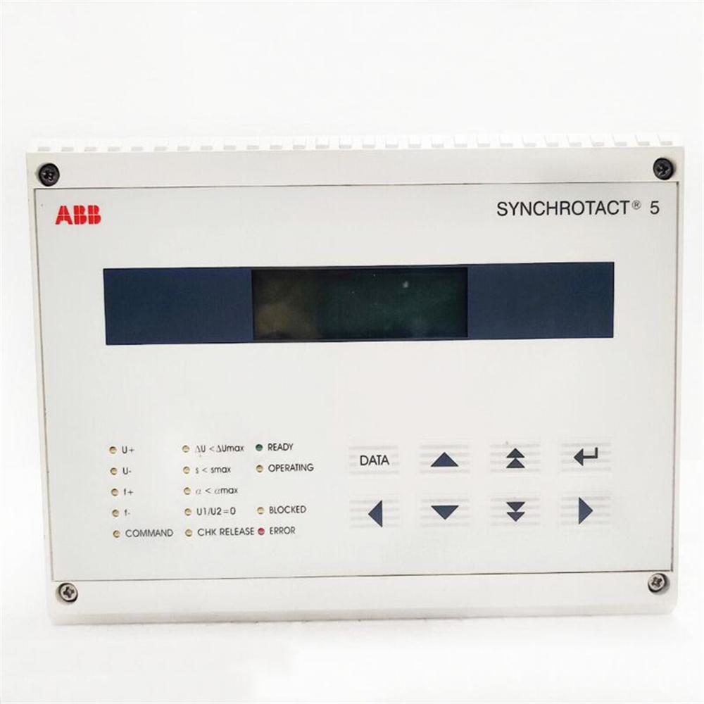
ABB Control UNIT SYN 5201A-Z, V277 3BHB006714R0277 is a control unit launched by ABB for synchronous and parallel operations, belonging to the ABB SYNC HROTACT series products. This product features a dual channel configuration, with one channel monitoring the operation of the other, greatly improving operational safety. It can be used to ensure precise timing and control in complex industrial systems and plays an important role in the field of industrial automation.

Product Usage

Mainly used to ensure precise timing and control in complex industrial systems, it is a key component in industries such as power generation, telecommunications, and industrial automation, where precise synchronization is crucial.

Performance characteristics

Rich communication interfaces: Supports logically independent dual Profibus DP buses, can set dip switches to specific communication rates or adaptively, can flexibly choose 1-2 Profibus DP electrical interfaces and 1-2 155 Mbps fiber optic interfaces, supports redundant dual network and fiber ring network topologies.

Long communication distance: Fiber optic communication distance exceeds 20 kilometers, with a 155 Mbps high-speed optical interface, which can better support long-distance reliable transmission of burst data.

Clear status indication: equipped with 5 dual color LED status indicator lights, with fiber optic link and power failure relay output alarm function.

Good protection performance: The electrical interface has 4000V lightning protection, 1.5A overcurrent, and 600W surge protection, meeting industrial design standards and passing EMC testing certification. Adopting DC (12-36V) wide redundant dual power supply, with reverse protection function, protection level of IP30, and shell reinforced with corrugated aluminum material.

Easy installation: Using standard industrial 35mm guide rail installation method, it is convenient to install in the control cabinet.

Technical parameters:

Safety level: PL e, SIL 3- SIL CL 3- PL e – Cat. 4.

Input/output: There are 8 digital inputs, 2 OSSD PNP outputs (400 mA at 24 VDC) with short circuit, overload, and reverse polarity protection, 2 PNP status outputs (100 mA), and 4 test outputs.

Working temperature: -10 ℃ to 55 ℃, storage temperature: -20 ℃ to 85 ℃.

Power supply: 24V DC ± 20%.

Dimensions: Approximately 108mm × 22.5mm × 114.5mm, gross weight of approximately 206.8g.

Key advantages

High security: With a dual channel design, one channel monitors the operation of the other channel, greatly improving the safety during the operation process and reducing the risk of system abnormalities caused by equipment failures.

Wide applicability: It not only supports 50/60Hz standard power grid, but also supports 16 2/3Hz frequency, suitable for various types of power generation equipment and complex power grid environments, whether it is conventional power plants or some special industrial self owned power plants.

Accurate synchronization performance: With advanced digital technology and precise algorithms, high-precision frequency and voltage matching and synchronization operations can be achieved, effectively improving the stability and reliability of power grid operation, reducing power fluctuations and equipment losses caused by poor synchronization.

Powerful communication capability: supports multiple communication protocols, facilitates integration with various devices, achieves intelligent management and remote control of the system, and can meet the needs of different users for centralized monitoring and management of the system.

High reliability: Complies with industrial design standards and has passed EMC testing certification. The electrical interface has 4000V lightning protection, 1.5A overcurrent, 600W surge protection, and adopts DC (12-36V) wide redundant dual power supply with reverse protection function. The protection level is IP30, and the shell is reinforced with corrugated aluminum material, which can operate stably in harsh industrial environments.

Precautions

During the installation process, it is necessary to strictly follow the instructions in the product manual to ensure the correct installation position and avoid equipment damage or performance degradation caused by improper installation. Special attention should be paid to the firmness and correctness of electrical connections to prevent problems such as short circuits or open circuits.

Before use, carefully inspect the appearance of the equipment for any damage and ensure that all components are complete. At the same time, it is necessary to confirm whether the parameters of the input power supply are consistent with the equipment requirements, in order to avoid irreversible damage to the equipment caused by power problems.

During operation, regular inspections of the equipment should be carried out to observe whether the operating status indicator lights are normal and whether there are any abnormal noises or heating phenomena. If any abnormalities are found, the machine should be stopped immediately for troubleshooting. Do not forcefully restart the equipment until the fault is resolved.

When setting and maintaining equipment parameters, it must be operated by professional personnel and carried out in the event of a power outage to prevent safety accidents or equipment failures caused by misoperation. At the same time, after the operation is completed, carefully check the parameter settings to ensure that they are correct and error free.

The device should be stored in a dry, ventilated, and non corrosive gas environment, avoiding direct sunlight and strong electromagnetic interference. If the device is not used for a long time, it is recommended to conduct regular power on checks to ensure that the device is functioning properly.

Similar model supplement

SYN5200A-Z: also belongs to the ABB SYNC HROTACT series products, similar to SYN 5201A-Z, designed for industrial automation synchronous control. The working voltage is 24V DC, and the communication protocol supports Ethernet/IP, Profibus, and Modbus. The difference lies in that its performance parameters such as processor speed may differ from SYN 5201A-Z, and there may also be differences in input and output capacity. For example, SYN5200A-Z may support a different number of I/O points in certain application scenarios, and users can choose according to their specific system requirements and budget.

ABB SYN5201a-Z, V217: This is also an automatic synchronization device, belonging to the SyncHROTACT 5 series product line. Compared with SYN 5201A-Z, V277, the input voltage range (measured input U1, U2) is 50 to 130 VAC (rated), and the auxiliary power supply (AC/DC) is 24-250 V DC, 100-230 V AC. There are differences in some detailed parameters, and there may also be differences in applicable conditions such as working environment temperature. For example, its working environment temperature is+5 to+70 ° C, and users need to choose it reasonably according to their actual usage environment and working conditions.

ABB SYNCHROTACT 5 SYN 5201a-Z,V2277 3BHB006714R2277 Reasonable price ...

ABB 3BSE017235R1 PXAH 401 Operator unit

Product Overview

ABB PXAH 401 Operator Unit (model: 3BSE017235R1) is an operation unit applied in the field of industrial automation. It plays a key role in connecting operators and industrial equipment in the industrial production process. Operators can monitor the real-time operation status of equipment through this unit, easily control the industrial process, and provide strong support for the efficient and stable operation of industrial automation systems.

Specification parameters

Input voltage: 24VDC

Working temperature range: -40 ℃ to 85 ℃

Communication Interface: Equipped with Ethernet interface for high-speed data transmission and network connection, RS232/485 interface can adapt to different communication protocol devices to achieve serial communication, and also has USB interface for convenient data storage and device debugging

Memory capacity: 512MB RAM for running programs and processing data, 1GB Flash for storing system programs, configuration files, and historical data, etc

Display screen size: typically 7 inches or larger, providing users with a clear visual interface for operation

Resolution: 800 x 640 pixels, ensuring clarity and readability of displayed content

Protection level: IP20, can effectively prevent dust in general indoor environments, providing basic protection for internal circuits of equipment

Functional Features

Multiple signal interfaces: Supports multiple signal input and output interfaces, including digital and analog signals, and can be connected to various sensors, actuators, and other devices to achieve the acquisition and control of various signals in industrial processes.

Rich control logic: Supports multiple control logics and algorithms, suitable for complex industrial control tasks, and can accurately control and adjust industrial processes according to different process requirements and control strategies.

High computing performance: It has high-performance computing capabilities, such as real-time analysis of 100000 level measurement point data in power dispatch systems, with a response time of less than 50ms, and can quickly process large amounts of real-time data, meeting the requirements of industrial automation systems for data processing speed and accuracy.

Redundant security design: Adopting redundant security measures such as dual machine hot standby design, the unplanned downtime is reduced from an average of 20 hours per year to 1.5 hours, improving the reliability and stability of the system and reducing production interruptions and losses caused by equipment failures.

Strong scalability: Through ABB’s CP600 series expansion module, up to 2048 I/O points can be connected, which can be flexibly expanded according to actual application needs, covering all scenario requirements from single machine control to whole plant integration.

Good environmental adaptability: With IP65 protection design, dustproof and waterproof, it can be directly installed in outdoor control cabinets, adapt to harsh industrial environments, and ensure stable operation under various complex working conditions.

Convenient human-computer interaction: Provides operators with an intuitive user interface that can display various process variables such as temperature, pressure, flow rate, etc., and allows operators to manually operate or adjust control parameters through a touch screen, facilitating real-time monitoring and control of industrial processes.

Industrial Internet compatibility: Built in OPC UA server can directly connect to MES and ERP systems to realize the transparency of production data, lay the foundation for digital factories, and facilitate enterprises to realize the informatization and intelligent management of production processes.

​Application area 

Pulp and paper industry: Used for pulp production lines and paper machine control, it can monitor and adjust parameters such as pulp concentration, flow rate, and paper machine speed in real time to ensure stable paper quality and improve production efficiency.

Power system: used in power plants and substations to monitor and control the operating status of equipment such as generators, transformers, and switchgear, achieve power dispatch automation, and ensure the stable operation and reliable power supply of the power system.

Metallurgical industry: used for monitoring and control of production processes such as steel and non-ferrous metals, such as blast furnace ironmaking, converter steelmaking, continuous casting and rolling, etc. It can accurately control parameters such as furnace temperature, pressure, liquid level, composition, etc., improve product quality and production efficiency, and reduce energy consumption and costs.

Manufacturing industry: used for process control and automation management of production line equipment, such as automotive manufacturing, mechanical processing, electronic equipment manufacturing, etc. It can achieve automated control of the start stop, speed adjustment, material conveying and other operations of various equipment on the production line, improve production efficiency and consistency of product quality.

Energy system: Used for energy scheduling and monitoring systems, such as smart grids, photovoltaic power stations, energy storage systems, etc., it can achieve real-time monitoring and optimized scheduling of energy production, transmission, distribution, and usage processes, improve energy utilization efficiency, and reduce energy consumption and costs.

Chemical industry: used for monitoring and control of chemical production processes, such as temperature, pressure, and flow control of reaction vessels, liquid level and temperature control of distillation towers, etc., which can ensure the safe and stable operation of chemical production processes, improve product quality and yield, and reduce environmental pollution.

Oil and gas industry: used for monitoring and controlling processes such as oil extraction, refining, and natural gas transportation, such as wellhead oil extraction equipment control, refining unit control, natural gas pipeline pressure and flow control, which can improve production efficiency, reduce production costs, and ensure production safety.

Pharmaceutical industry: used for monitoring and controlling the pharmaceutical production process, such as the operation control of drug production equipment, drug quality testing, inventory management of raw materials and finished products, etc., to ensure that the drug production process complies with GMP standards, improve drug quality and production efficiency.

Key advantages

High reliability: High quality electronic components are selected and advanced redundancy design concepts are adopted to ensure stable operation of equipment in harsh industrial environments such as high temperature, high humidity, and strong electromagnetic interference, reducing the probability of equipment failure and minimizing production losses caused by equipment downtime.

Usability: Equipped with a simple and user-friendly human-computer interaction interface, supporting multilingual operations, both experienced professional engineers and first-time operators can quickly get started and easily complete various operational tasks.

Scalability: Based on the modular design concept, this operating unit is easy to upgrade and expand the system. Users can flexibly add functional modules or expand communication interfaces according to actual production needs to adapt to the constantly changing requirements of industrial automation control.

Precautions

Installation environment: It should be installed in a dry, well ventilated environment without strong electromagnetic interference, avoiding direct sunlight and severe vibration to ensure the normal operation and service life of the equipment.

Power supply: Ensure stable input power supply, meet the specifications of 24VDC, and prevent equipment damage or abnormal operation caused by power fluctuations or abnormalities.

Regular maintenance: It is necessary to regularly clean the equipment, check whether the communication interface connection is secure, and regularly backup important data to ensure stable operation and data security of the equipment.

ABB Plantguard Safety Instrumented System

System Overview

Positioning: Plantguard is a safety instrumented system that complies with international safety standards such as IEC 61508 and IEC 61511, designed specifically for safety critical control in industrial processes. It is used to monitor hazardous conditions and trigger protective measures (such as emergency shutdown and energy cut-off), reduce accident risks, and ensure the safety of personnel, equipment, and the environment.

Core objective: To achieve Safety Instrumented Function (SIF) through highly reliable hardware architecture and software functionality, supporting safety integrity level requirements from SIL 1 to SIL 3.

System architecture

Hardware Architecture

Adopting modular and redundant design to ensure high availability and fault tolerance:

Controller: Based on the AC 800M series safety controllers (such as PM865, PM867, etc.), it supports safety architectures such as 1oo2 (1 out of 2) and 2oo3 (2 out of 3), meeting different SIL level requirements.

I/O module: including safety input/output modules (such as AI801S, DI801S, DO801S), with signal isolation and diagnostic functions, supporting multiple on-site signals (4-20mA, switch values, etc.).

Communication network: Adopting redundant industrial Ethernet (such as PROFINET, Ethernet/IP) and fieldbus (such as PROFIBUS DP) to ensure the security and real-time transmission of data, supporting integration with DCS, PLC and other systems.

Software architecture

Based on a unified engineering platform, simplify configuration and maintenance:

Engineering tool: Use Control Builder M software for safety logic configuration, supporting programming methods such as Function Block Diagram (FBD) and Ladder Diagram (LD), and built-in safety function block library (such as emergency stop and interlock logic).

Diagnosis and monitoring: System status monitoring, fault diagnosis, and event recording are achieved through Operator Station or Asset Optimization software, supporting online maintenance and testing without affecting the operation of safety functions.

Core functions and advantages

Safety function

Support custom security logic to implement safety controls such as emergency shutdown (ESD), fire and gas monitoring (F&G), burner management (BMS), etc.

Equipped with online testing and partial trip testing (PST) functions, reducing parking maintenance time and improving system availability.

integration capability

It can seamlessly integrate with ABB’s AC 800M process control system, Panel 800 operator panel, etc., achieving synergy between safety and process control.

Support open protocols (such as OPC UA, Modbus) for easy communication with third-party systems (such as ERP, MES), forming a complete industrial security ecosystem.

Compliance and reliability

Compliant with international standards such as IEC 61508 (SIL 1-3) and IEC 61511, certified by authoritative organizations such as T Ü V and EXIDA.

The hardware has a high mean time between failures (MTBF), supports redundant design and hot plugging, ensuring that a single point of failure does not affect system operation.

Application scenarios

Plantguard is widely used in industrial fields with strict safety requirements, including:

Petrochemical and natural gas processing (such as refineries and LNG plants);

Pharmaceuticals, food and beverage (such as hazardous material processing);

Energy industry (such as power plants, new energy projects);

Chemical and metallurgical industries (such as high-temperature and high-pressure reaction processes).

Customer Value

Risk reduction: By implementing reliable safety controls, the incidence of accidents can be reduced, in compliance with regulatory requirements.

Efficiency improvement: Online testing and diagnostic functions reduce downtime and improve production continuity.

Full lifecycle support: from engineering design, installation and debugging to operation and maintenance upgrades, providing full technical support to ensure long-term stable operation of the system.

image.png

ABB AC 800M 6.0 Controller Hardware

Product overview

Positioning: AC 800M 6.0 is a high-performance modular controller hardware platform that can achieve various process and industrial automation control functions through programming. It is suitable for various industrial scenarios and can serve as an independent controller or undertake local control tasks in the control network.

Core composition: It consists of hardware components such as processor unit, communication interface, power supply unit, battery backup unit, etc. Some high integrity systems also require special modules such as SM810/SM811/SM812.

Hardware components and functions

Processor Unit

Category: Including PM851/PM851A、PM856/PM856A、PM858、PM860/PM860A、PM861/PM861A、PM862、PM864/PM864A、PM865、PM866/PM866A、PM867、PM891  There are differences in performance and configuration among different models, such as PM891 using MPC8270 microprocessor with a running speed of 450MHz, which is about three times the performance of PM864.

Function: Includes microprocessor, RAM memory, real-time clock, LED indicator lights, initialization button, etc., responsible for running firmware and application programs, and controlling the operation of the entire system. Support redundant configuration, with a primary backup switching time of less than 10ms, and the process output remains frozen during switching.

Communication interface

Diverse types: including RS-232C(CI853)、PROFIBUS DP(CI854/CI854A/CI854B)、MasterBus 300(CI855)、S100 I/O(CI856)、INSUM(CI857)、DriveBus(CI858)、FOUNDATION Fieldbus HSE(CI860) Multiple interfaces are available to expand the communication capabilities of the processor unit, supporting different protocols and device connections.

Function: Implement communication between the controller and external devices, networks, such as connecting remote I/O, fieldbus instruments, drivers, etc.

Power and battery backup

Power supply units, such as SD831, SD832, SD833, SD834, etc., are switch mode power converters that convert AC or DC inputs into stable 24V DC outputs. They support redundant configurations and need to be used in conjunction with voting units (such as SS823, SS832).

Battery backup: includes internal batteries (some models) and external batteries (SB821, SB822), used to provide backup power for memory and real-time clock in case of power failure. SB822 is a rechargeable lithium battery, while PM891 only supports external battery backup.

Other Components

CEX Bus interconnect units, such as BC810 and BC820, are used to divide CEX Bus into independent segments, improve system availability, and support redundant communication interfaces.

SM modules: SM810, SM811, SM812 are used for intelligent monitoring of high integrity controllers. SM811 and PM865, SM812 and PM867 can form a 1oo2 structure, supporting SIL3 applications respectively.

Technical Parameter

Processor performance: Different models of processors have different microprocessor models, operating frequencies, memory capacities, etc. For example, PM864/PM865 uses the 96MHz MPC862 microprocessor, while PM891 uses the 450MHz MPC8270 microprocessor.

Communication capability: Supports multiple communication protocols and rates, such as PROFIBUS DP supporting 9.6kbit/s-12000kbit/s, Ethernet ports supporting 10/100Mbit/s, etc.

Power parameters: The input voltage range, output voltage, and rated current of the power supply vary. For example, the SD831 has an input of 100-240V AC or 110-300V DC and an output of 24V DC/3A.

Environmental parameters: working temperature, storage temperature, humidity, etc. The working temperature range is usually -25 ° C to+60 ° C (some models may vary), and the relative humidity is 5% -85% without condensation

ABB Panel 800 Version 6 Series Operator Panel

Product overview

The Panel 800 Version 6 series is a user-friendly, intuitive, and ergonomic operator panel designed to be compact, space saving, and equipped with advanced features. It supports process and equipment control through function keys next to the screen or touch LCD display screens, making it suitable for process monitoring and operation in industrial automation scenarios.

Product classification and core parameters

This series is divided into three categories: standard panels, high-performance panels, and reinforced panels. The specific models and parameters are as follows:

Category, Model, Display Screen Size, Resolution and Proportion, Core Configuration Size (W × H × D, mm), Protection Level (Front/Rear), Operating 

Temperature Range

Standard panel PP871 4.3 “480 × 272 (16:9) ARM9 processor (400MHz), 128MB memory 145 × 103 × 49 IP66/IP20-10~+60 ° C

PP874 7 “800 × 480 (16:9) Same as above 204 × 143 × 49 IP65/IP20 Same as above

PP877 10.4 “640 × 480 (4:3) Same as above 280 × 228 × 51 Same as above

PP874K/PP877K 7 “/10.4” with button operation as above, other models are slightly larger than PP874/PP877 and the same as above

High performance panel PP882 12.1 “1280 × 800 (16:10) Intel Atom processor (1.1GHz), 1GB memory 340 × 242 × 79 IP65/IP20-10~+50 ° C

PP885 15.4 “Same as above 410 × 286 × 83 Same as above

Reinforced panel PP880R 7 “800 × 480 (16:9) 1.0GHz Intel Atom, 3.5GB storage 204 × 143 × 73 IP66/IP20-30~+70 ° C

PP885R/PP886H 15.4 “1280 × 800 (16:10) 1.0/1.6GHz Intel Atom 410 × 286 × 83 Same as above

Common parameters:

Interaction mode: resistive touch (million touch cycles) or button operation (million press cycles).

Interface: All are equipped with Ethernet (RJ45), USB 2.0, RS232/RS422/485 serial ports, and support SD card expansion storage.

Power supply: 24VDC (18-32VDC), power consumption varies from 3.6W to 28W depending on the model.

Communication function

Supports multiple industrial communication protocols and drivers, and can be integrated with mainstream PLCs and control systems, including:

ABB proprietary protocols: COMLI (master/slave), Control Network MMS, Freelance 2016, etc.

Universal protocols: Modbus (ASCII/RTU/TCP, master/slave), Profinet, Ethernet/IP, OPC DA/UA, etc.

Third party agreements: Siemens S7 series, Schneider Uni Always, Rockwell DF1, etc., covering nearly 50 types of drivers.

ABB System proS series enclosed starter

Product Overview

Series positioning: System proS enclosed starters include direct online (D.O.L.) starters and dual speed starters, including non combination and combination types, suitable for 1-phase and 3-phase motor control, with a maximum CSA/UL horsepower rating of 7.5 to 125HP at 600VAC.

Core features: Compact and space saving design, pre wired indicator light components and control transformer kit for easy on-site modification and installation, anti misoperation design for terminals, all connection terminals can prevent accidental contact, and necessary terminal blocks and wiring are also included. The starter can be controlled through external holding contacts.

Starter type and specifications

1-phase starter

Non combination: Divided by contactor size (AF09, AF16, AF30, AF52, AF80), corresponding to different CSA motor switch currents and maximum motor horsepower ratings (120V and 240V), and providing models of different housing types (Type 1, Type 4/12, Type 4X).

Combination type: including types of fuse isolation switches and non fuse isolation switches, also divided according to the size of the contactor, corresponding to different motor parameters and housing models.

3-phase starter

Non combination type: There are types such as irreversible, reversible, and dual speed (2 windings and 1 winding), divided according to the size of the contactor (AF09, AF16, AF30, AF52, AF80, AF140), corresponding to the maximum motor horsepower rating at different voltages, and providing models of different housing types.

Combination type: including types of fuse isolation switches, non fuse isolation switches, and MCP circuit breakers, divided by contactor size, corresponding to different motor parameters and housing models.

Core parameters and selection

Coil voltage: Provides multiple options such as 24-60V, 48-130V, 100-250V, 250-500V, etc., which can be distinguished by the last digit of the catalog number.

Overload relay: Class 10 adjustable overload relay is used, and different contactor sizes correspond to different models of overload relays. The current setting range and cable range are different, and the selection should be based on the motor parameters.

Catalog number explanation: The number includes information such as housing type, combination method, starter type, contactor size, coil voltage, overload selection, indicator light components, auxiliary contacts, etc. The specific model can be determined according to the needs.

Attachment

Indicator light components: There are various types, including combinations with buttons and indicator lights, switches and indicator light combinations in different positions, etc., which can be installed by customers or factories. They are suitable for different types of starters and come in versions such as 130V and 24V, with different functions and identifications.

Transformer kit: Divided by contactor size and VA rating, there are options such as 50VA and 100VA. The input (primary) voltage ranges from 120-600V, and the output (secondary) voltage is 24V and 120V. It can be factory installed.

Technical data and installation

Technical parameters: Main protection, contactor, maximum overload, combined short-circuit current, AC1 and AC3 rated current, and corresponding horsepower of single-phase and three-phase motors for different types of starters.

Size specifications: Dimensions (height, width, depth) of starters of different types (non combination, combination) and different housing types (Type 1, Type 4/12, Type 4X).

Electrical diagram: including electrical wiring diagrams for direct online starters, single-phase 2-pole starters, reversible starters, dual speed 2-winding starters, etc., as well as electrical diagrams for indicator light components.

ABB Tmax T7 series molded case circuit breaker

Product Overview

Series positioning: The Tmax T7 series is a high current model in ABB molded case circuit breakers, covering a current range of 630A-2500A, designed to meet the needs of high reliability, high breaking capacity, and compact design in industrial distribution systems.

Product types: including distribution circuit breakers (with thermal magnetic or electronic release), motor protection circuit breakers, etc., suitable types can be selected according to different application scenarios.

Core technical parameters and performance

Breaking capacity: At 480V AC voltage, the breaking capacity can reach 150kA, which can effectively deal with short-circuit faults and ensure system safety.

Release type:

Thermomagnetic release: Provides overload and short circuit protection, with relatively fixed parameter settings, suitable for conventional protection scenarios.

Electronic release devices (such as PR231/P, PR232/P, etc.): have more precise protection functions, support multiple protection curves, and can provide precise protection against overload, short circuit, grounding faults, etc. Some models also support communication functions (such as Modbus RTU), making remote monitoring and management easier.

General parameters: protection level IP54, insulation level F, temperature rise level B (some models are F), operating temperature range -25 ℃ to+70 ℃, storage temperature -40 ℃ to+70 ℃, in compliance with multiple international standards such as IEC 60947-2.

Installation and Configuration

Installation method: Supports fixed installation, plug-in installation, and pull-out installation. Multiple installation methods can meet different cabinet design and maintenance needs. Some models can be converted to different installation methods through conversion kits.

Connection method: Provides multiple terminal types, including front wiring, rear wiring, multi cable terminals, etc., suitable for copper and aluminum cables, making it easy to connect with different lines.

Accessories: Equipped with a variety of accessories such as auxiliary contacts, undervoltage release, shunt release, remote control mechanism, residual current release, etc., the circuit breaker function can be expanded according to actual needs.

Application and Authentication

Application scenarios: Widely used in industrial power distribution systems, large building power distribution, energy industries, and other fields, it can be used for main power distribution, feeder line protection, and protection of large motors.

Certification: Compliant with multiple international standards such as UL 489, CSA C22.2, IEC, and some models have been certified by classification societies (such as ABS, RINA, etc.) to ensure the applicability of the product in different regions and industries.

ABB UK 500 series household distribution box

Product Overview

Design concept: Integrating years of market experience and innovative design, balancing technical performance and decorative appeal, meeting high standards of functionality and aesthetic needs. The white standard version adopts modern design and is suitable for various decoration styles.

Core advantages: Easy installation (single handed cable operation, quick snap fastener fixation, etc.), high flexibility (supporting multiple installation methods and extensions), strong security (complying with multiple standards).

Structure and installation characteristics

Box design:

Made of non warped, drop resistant, and non combustible plastic material (compliant with UL 94-V2 standard), with a large internal space and equipped with cable strain relief comb. There are pre formed cable entrances on the side and back.

Wall mounted grip is a standard configuration that can reduce installation depth or serve as a spacer for multiple distribution boxes installed side by side. It can be flipped to provide two insertion depths.

Installation method:

Support embedded installation, hollow wall installation can be achieved through the UZ 90 E hollow wall installation kit, without the need for a dedicated distribution box.

The equipment bracket adopts a snap on system, which can be quickly installed without tools. The DIN rail is double insulated, and the N/PE terminals and N-RCD terminals are plug-in. All clips comply with VBG 4 standards to prevent accidental contact.

Cover plate and door frame:

The cover plate is fixed with two 900 quick action locking screws, which can be sealed, and the slot width can be expanded from 12 modules to 14 modules.

The decorative frame and door are easy to disassemble and can adapt to uneven surfaces.

Product series and models

Basic version: No decorative frame and door, including box body, equipment bracket, movable DIN rail, cover plate, N/PE terminal, N-RCD clamp terminal, wall clamp, label system, etc. It is divided into four types according to module width: 12 (14), 24 (28), 36 (42), 48 (56), corresponding models are UK 510 BE, UK 520 BE, UK 530 BE, UK 540 BE, and the dimensions (HxWxD), niche dimensions, wall cut dimensions, and weight are given respectively.

Standard version and options: with decorative frame and door, there are various styles of decorative frame and door, such as:

Standard version: Alpine white (RAL 9003) powder coated steel plate material.

Art line “: Made of brushed stainless steel material.

“Additional line”: Photo frame doors made of brushed aluminum or coated with anodized color.

Color line “: There are metal coatings such as Bordeaux red, anthracite, midnight blue, etc.

Transparent door design.

Different styles are compatible with different base models and have corresponding internal and external dimensions.

control panel:

The front-end control panel can be used to monitor and operate building functions (such as lighting systems), using standard UK 500 components, with a sturdy aluminum frame and anodized front panel and safety lock.

There are three models (FPT 510 E, FPT 520 E, FPT 530 E) with different external dimensions, which can be decorated by the user or pre installed and printed by the factory.

Accessories and replacement parts

Including enclosure, wall clamp, quick action screws, hollow wall installation kit, surface installation kit, N and PE terminals, N-RCD terminals, labeling system, cable ties, screws, mounting plates, snap closures, safety locks, slot covers, cable entrances, vertical and horizontal partitions, etc., the product models that each accessory is compatible with are listed in detail.

Technical Standards and Certification

Compliant with DIN VDE 0603, DIN 43

871, German Institute of Engineers standard VDE 0100/729, etc., with an IP protection level of IP 30 and a rated current of 63A.

image.png

ABB contactors and overload relays

Product Series Overview

The document covers multiple contactor and overload relay series under ABB, with core products including:

Contactor:

AX series: suitable for low-voltage distribution and motor control, with a current range of 6A-1000A, supporting AC/DC coils, featuring compact design and high mechanical life (≥ 10 million cycles).

AF series: designed for frequent operation scenarios such as elevators and cranes, with a current range of 9A-400A and a mechanical lifespan of up to 30 million cycles.

A-series: Classic series, covering 12A-630A, supports multiple coil voltages, and is compatible with global standards.

Overload relay:

TA series: Thermal overload relay, used in conjunction with contactors, with a current range of 0.1A-630A, providing manual/automatic reset function.

TF series: Electronic overload relay with precise protection (overload, phase loss, locked rotor, etc.), supporting communication functions (such as Modbus), current range of 0.1A-800A.

Combination product: Pre assembled units for contactors and overload relays (such as AX+TA, AF+TF), simplifying selection and installation.

Core technical parameters and performance

Key indicators of parameter categories

Electrical performance – rated voltage: AC below 690V, DC below 250V (some models support higher voltages).

-Breaking capacity: It can reach 10 times the rated current under AC-3 load (such as AX18 with a breaking capacity of 100A at 400V).

-Coil power consumption: AC coil ≤ 15VA, DC coil ≤ 10W, energy-saving coil power consumption reduced by more than 50%.

Mechanical performance – Operating frequency: up to 1200 times/hour (AX series), AF series supports higher frequencies (such as 3600 times/hour).

-Protection level: The contactor body is IP20, and after installing a casing, it can reach IP65.

-Installation method: DIN rail installation (35mm) or screw fixation, supporting vertical/horizontal installation.

Protection Function – Overload Relay: The TA series achieves overload protection through bimetallic strips, while the TF series has an electronic trip curve (Class 10/20/30) and customizable protection parameters.

-Contactor: equipped with an arc extinguishing cover to reduce damage to the contacts caused by the arc, and supports reversible control (through mechanical interlocking).

Environmental adaptability – Operating temperature: -25 ° C to+70 ° C (some models -40 ° C to+70 ° C).

-Vibration resistance: 10-55Hz, amplitude 0.75mm; Impact resistance: 30g (11ms).

Selection and Application Guide

Selection criteria: Select the model based on the load type (motor, lighting, electric heating, etc.), rated current, operating frequency, protection requirements (overload, short circuit, etc.), and environmental conditions (temperature, humidity). The document provides a detailed selection table, including the current matching relationship under different load types (such as AC-1 resistive load, AC-3 motor load).

Typical application scenarios:

Industrial motor control (pumps, fans, conveyors).

Low voltage distribution system (distribution box, switchgear).

Building automation (air conditioning, elevators).

Renewable energy sources (photovoltaic inverters, wind power converters).

Installation and maintenance

Installation points:

Wiring: The main circuit uses copper or aluminum cables (with copper aluminum transition terminals), and the cross-sectional area of the control circuit wires is 0.5-2.5mm ², with a tightening torque of 0.5-2.5Nm (depending on the terminal specifications).

Spacing requirement: Contactors of different current levels must maintain a certain electrical clearance (such as 100A or above ≥ 15mm) to ensure heat dissipation and insulation.

Maintenance suggestion: Regularly check contact wear (replace when thickness ≤ 1mm), clean the arc extinguishing cover, test the accuracy of overload relay action, and avoid long-term operation in dusty and corrosive environments.

Certification and Standards

Compliant with international standards: IEC 60947-1/4 (contactors), IEC 60947-5-1 (overload relays).

Certification coverage: CE, UL, CSA, CCC, GL (Classification Society), etc., applicable to the global market.

Additional Information

Provide technical charts such as product size diagrams, wiring diagrams, trip curves (overload relays), and lifespan curves to assist in installation and debugging.

Contains environmental information: The product materials comply with the RoHS directive, and the proportion of recyclable parts is ≥ 90%.

Emphasize safety reminder: Installation should be operated by professional electricians, and maintenance should be carried out after power failure to avoid electric shock or mechanical injury.

ABB NTAC-0x pulse encoder interface module

Safety instructions

Warning types: including dangerous voltage warning, general warning, electrostatic discharge warning, reminding users to have professional electricians perform electrical installation and maintenance. Drivers and related equipment must be properly grounded. After power failure, wait for 5 minutes for the intermediate circuit capacitor to discharge, and use voltage indicating instruments to confirm the completion of discharge. At the same time, be aware of the risks that may arise from the automatic reset function of the driver.

Attention: Emphasize following the manufacturer’s operating instructions to avoid hazards such as electric shock.

Overview

Scope of application: Applicable to NTAC-02 (revised version C and above), NDIO-02 (revised version A and above), NAIO-03 (revised version A and above), and includes reference information from earlier versions (NTAC-01, NDIO-01, NAIO-01/02).

Module function:

NTAC-02: Provides a digital pulse encoder interface for obtaining precise speed or position feedback of the motor shaft.

NDIO-02: Provides 2 digital inputs and 2 relay outputs.

NAIO-03: Provides 2 analog inputs and 2 analog outputs, with signal resolution (12 bits) superior to standard analog I/O.

Communication link: Connected to the frequency converter through an optical DDCS protocol communication link, the module and NIOC standard I/O board usually form a circular connection on the CH1 channel of the NAMC board, which acts as the main station to cyclically poll other stations.

install

Module Node Number Setting: Different modules (NTAC, NDIO, NAIO) have their own node numbering rules set through DIP switches inside the module casing. The new settings will take effect when the module is powered on next time.

Mechanical installation: It can be installed inside or outside the drive. When installing outside, attention should be paid to wiring, space, environmental conditions, and grounding requirements. When installing inside, it should be operated by a professional electrician, following steps such as power-off, discharging, and removing the cover plate.

ACS 600 connection: Use fiber optic cables to connect to the NAMC/NDCO board of the driver, paying attention to the color coding of the connectors (blue for RXD, gray/black for TXD). Multiple modules are connected in a circular manner on the same channel, and the terminals connected to different modules vary depending on the application.

Detailed installation and configuration of each module

NTAC-02 pulse encoder interface module: introduces terminal identification, current consumption, wiring requirements (cable type, length, shielding grounding, etc.), encoder output type connection diagram (push-pull, collector open circuit, emitter open circuit), and programming method (set through driver parameters).

NDIO-02 digital I/O expansion module: including terminal identification, wiring recommendations, DI1 hardware filter suppression settings, and programming methods (activating communication through driver parameters).

NAIO-03 Analog I/O Expansion Module: Includes mode selection (unipolar/bipolar), input signal type selection (current/voltage), terminal identification, wiring requirements, programming methods (activates communication through driver parameters to ensure parameter settings correspond to module mode switches).

Appendix Information

Technical data: including detailed technical parameters such as I/O expansion links, enclosure of each module, installation, connectors, input and output.

Environmental conditions: lists the environmental requirements for temperature, humidity, vibration, impact, etc. of the module during operation, storage, and transportation.

Early version information: Introduces the differences, terminal identification, settings, and other information between NTAC-01, NDIO-01, NAIO-01/02 and their corresponding new versions.

​Install and start ABB NTAC-0x module

Installation preparation

Confirm compatibility

The module needs to be used in conjunction with the ACS 600 series frequency converter, and the application version must be ≥ V5.0 (standard application) or ≥ V4.2 (system application).

Check the encoder type (push-pull, open collector or open emitter) and prepare matching connecting cables.

Safe power outage

Disconnect the main power supply of the frequency converter and wait for 5 minutes until the intermediate circuit capacitor discharges completely.

Use a voltage indicator to confirm that there is no residual voltage.

Physical installation steps

1. Node number setting

Open the module casing and set the node number (range: 1-31) through the DIP switch.

Rule:

The NTAC module number needs to be an even number (such as 2, 4, 6…).

Node numbers within the same channel cannot be duplicated.

After the setting is completed, it will take effect when powered on again.

2. Mechanical installation

Internal installation (recommended):

Remove the cover plate of the frequency converter and insert the module into the CH1 channel of the NAMC board or NDCO board.

Connect the RXD (blue interface) and TXD (gray/black interface) of the module using fiber optic cables to form a circular topology.

External installation:

Choose a dry and ventilated location to ensure that the ambient temperature is between -25 ° C and+55 ° C.

Fix the module with M4 screws and maintain a minimum spacing of 50mm.

3. Encoder connection

Select the corresponding terminal based on the encoder type (such as A+/A -, B+/B -).

Wiring requirements:

Use shielded cables with both ends of the shielding layer grounded.

The encoder cable should be kept at least 100mm away from the power cord to avoid interference.

Maximum cable length: push-pull encoder ≤ 100m, differential encoder ≤ 300m.

Electrical connection

1. Power connection

The module is powered internally by the frequency converter and does not require additional power supply.

2. Fiber optic communication connection

Connect the RXD (receiver) of the module to the TXD (transmitter) of the previous node to form a circular link.

The TXD of the last module needs to be connected back to the NAMC board or NDCO board of the frequency converter.

3. Encoder signal connection

Push pull encoder: directly connected to the digital input terminal of the module.

Differential encoder: Connected after conversion by a differential receiver.

Troubleshooting

communication failure

Check if the fiber optic connection is secure and if the interface is clean.

Confirm that there are no conflicts in the node numbers and that all module numbers are even.

Encoder signal loss

Check if the encoder power supply is normal (usually+5V or+24V).

Use an oscilloscope to check if the encoder output waveform is stable.

Parameter not effective

Restart the frequency converter and ensure that the parameters are saved to non-volatile memory.

Precautions

Static protection: Wear an anti-static wristband before operation to avoid touching the circuit board.

Environmental requirements: Avoid installation in damp, dusty, or strong electromagnetic interference environments.

Maintenance: Regularly clean the module’s heat dissipation holes and check for dust or damage to the fiber optic interface.

Search for products

Back to Top
Product has been added to your cart