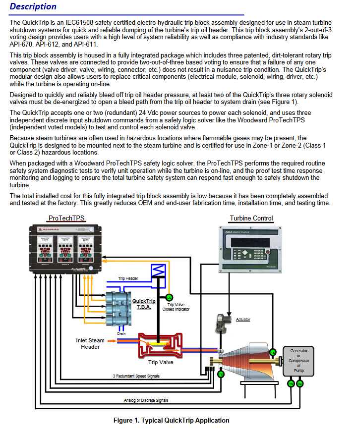
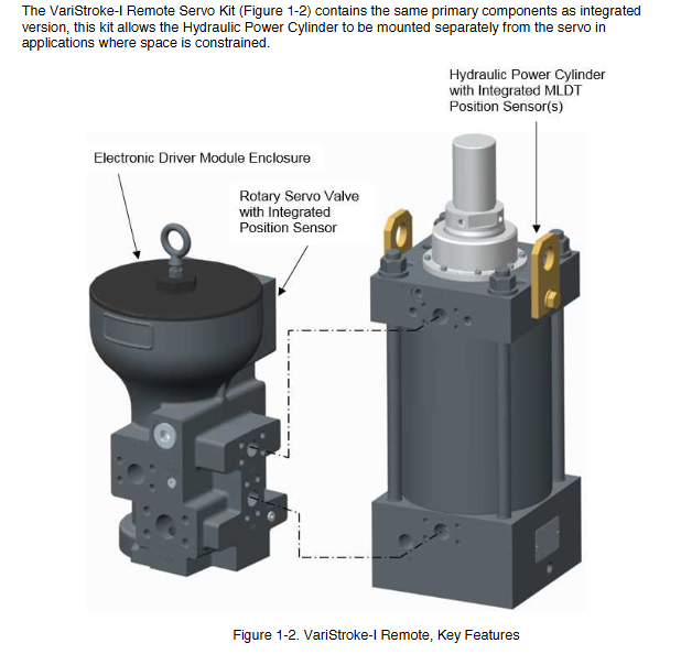
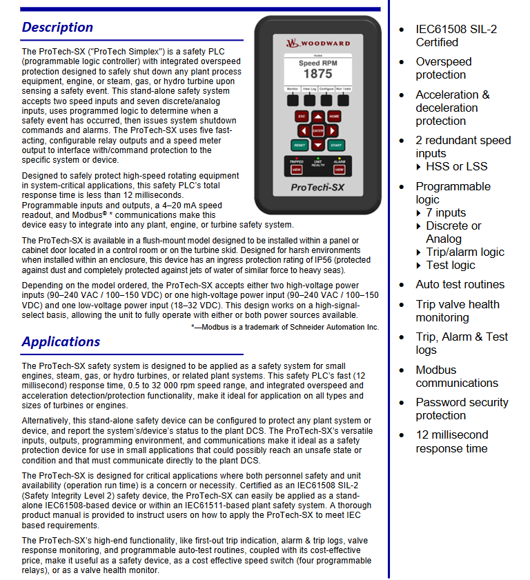
Call us 24/7uaedcs@163.com
Welcome to the official website of CNIACS Automation Technology Co., Ltd!
Call us 24/7uaedcs@163.com

TOSHIBA V200 series programmable logic controller

Document Overview and Product Positioning

1.1 Core positioning of the document

Document number: UM-V200-E001, initial version released in January 2012, is a technical guide for the entire lifecycle of V200 series PLCs, covering the entire process from unboxing installation to fault maintenance.

Target audience: Qualified Person operators are required, who possess electrical equipment installation/maintenance skills and have received safety training (in compliance with NFPA 70E standards).

1.2 Core Product Parameters

The V200 series is divided into basic models and extended models. The core parameters of the basic models are compared as follows:

Basic model, local I/O configuration, expansion capability, communication interface, high-speed counting capability, size (mm), weight (gm)

GPU288 * 3S 8-in (digital)/8-out (6 relays+2 transistors) supports 8 expansion modules COM1 (RS232/RS485), COM2 (RS485), USB 2-channel single-phase (50kHz), 1-channel orthogonal (5kHz) 100 × 35 × 70 200

GPU232 * 3S 16 in (digital)/16 out (digital) without expandability COM1 (RS232), COM2 (RS485), USB 2-channel single-phase (50kHz) 155 × 102 180

GPU200 * 3S without local I/O support 8 expansion modules COM1 (RS232/RS485), Ethernet, USB 2-channel single-phase (100kHz) 100 × 35 × 70 200

The expansion models include digital expansion (such as GDI216S: 16 digital inputs) and analog expansion (such as GAD208S: 8 analog inputs), supporting flexible configuration of I/O points.

Safety operation standards (top priority)

2.1 Definition of Warning Signs

The document specifies the risk level through “identification+text”, and all identification is printed on the equipment body and key positions in the manual:

Core meaning of warning signs Typical scenarios

DANGER operational errors can result in death or serious injury (such as high-voltage electric shock, fire). Opening terminal covers and contacting high-voltage components when powered on

Incorrect operation of Warning may result in serious injury or equipment damage (such as device falling or burning). Handheld terminal cover handling or touching the heat sink

CAUTION operation errors can result in minor injuries or equipment malfunctions (such as loose terminals, electrostatic damage), ungrounded operations, and wiring errors

2.2 Core Security Rules

Prohibited operation list:

Do not open the power terminal cover (which contains 24VDC high-voltage components) when powered on.

Do not insert foreign objects such as wires, tools, dust, etc. into the ventilation openings or terminal slots of the equipment (to prevent short circuits).

It is prohibited to disassemble or modify hardware without authorization (such as replacing non original capacitors), as this will result in warranty failure and safety risks.

It is prohibited to use unverified models in explosion-proof environments (such as flammable gas areas).

Mandatory operation checklist:

Before installation/maintenance, it is necessary to read the manual thoroughly and confirm that the operator is a Qualified Person.

After power failure, wait for at least 15 minutes and use a multimeter with 800Vdc or higher to check that the voltage of the DC main circuit (PA/+and PC/-) is ≤ 45V before operation.

Reliable grounding is required: D-type grounding is used for 240V level, C-type grounding is used for 500/600V level, grounding resistance is ≤ 4 Ω, and the grounding wire specification is not less than the main circuit wire.

When enabling the Auto restart function, a warning label stating ‘Possible sudden restart’ should be affixed next to the device.

Hardware installation and wiring

3.1 Installation environment requirements

The allowable range of environmental indicators and the prohibited range

Environmental temperature 0 ℃~55 ℃ (operation), -20 ℃~85 ℃ (storage) exceeding 55 ℃ (triggering overheating protection), below -20 ℃ (capacitor failure)

Relative humidity 20%~90% (no condensation) Condensation environment, humidity>90% (causing short circuit)

Vibration requirement ≤ 5.9m/s ² (5-150Hz) exceeding 5.9m/s ² (additional anti vibration pads need to be installed)

Environmental cleanliness without dust, metal powder, corrosive gas, dense dust, and oil mist environment (blocking heat dissipation)

3.2 Wiring specifications

Main circuit wiring:

Power input: 24VDC ± 15%, requires separate wiring (threaded separately from the control circuit), terminal screw torque: M3 is 0.5N · m, M4 is 1.4N · m.

Digital input: 24VDC, current per point 5mA (high-speed input 20mA), input impedance 5.4k Ω (high-speed input 1.2k Ω).

Digital output: Relay type (230V/2A, 30VDC/2A), transistor type (24VDC/0.5A), output terminals need to be wired according to the “set of common terminals every 4 points”.

Communication wiring:

RS485: 2-wire system, maximum transmission distance of 1200m, supports 32 nodes, requires 120 Ω terminal resistors to be connected at both ends of the bus.

USB: For programming only, using USB 2.0 Type B interface, cable length ≤ 2m.

Ethernet (GPU200 * 3S): RJ45 interface, supports 10/100Mbps adaptive, requires shielded Ethernet cable.

Software Configuration and Programming

4.1 OIL DS software installation

System requirements:

Operating systems Windows 2000 (SP4), XP (SP2), Vista

Processor ≥ 800MHz (Vista requires ≥ 1GHz)

Memory ≥ 256MB (Vista requires ≥ 1GB)

Hard disk space of 800MB (including 200MB. NET Framework)

Display resolution 1024 × 768 (16 bit high color)

Installation steps:

Run Setup. exe and select the installation path (default C: \ Program Files \ OIL DS).

Wait for the installation to complete and start the software through “Start → Program → OIL DS”.

When uninstalling, execute through “Start → Program → OIL DS → Uninstall OIL DS”.

4.2 Ladder diagram programming

Core process:

New project: Select V200 model (such as GPU288 * 3S), configure project name and storage path.

Define Tag Database: Assign I/O addresses (such as X0000 corresponding to digital input 1) and register types (input X/output Y/configuration MW).

Edit ladder diagram: Drag and drop “normally open contact (NO)”, “coil”, “function block (such as MOV-W)” to construct logic, supporting subroutines and interrupt programs.

Compile and Download: Press F9 to compile (if there are no errors, it will display “Compilation Successful”), and download it to the PLC via USB/RS485.

Program type:

Main program: It runs in a loop during normal operation and needs to end with the “END” instruction.

Subroutine: Called with the “CALL” instruction and returned with the “RET” instruction.

Interrupt program: Timer interrupt (5-1000ms), I/O interrupt (triggered by high-speed counting), must end with the “IRET” instruction.

Detailed explanation of special I/O functions

5.1 High speed counter

Function type:

Type Input Channel Maximum Frequency Counting Range Application Scenarios

Single phase counter 2-channel (X000/X001) 50kHz 0~4294967295 (32-bit) pulse counting (such as encoder)

Single phase speed counter 2-channel (X000/X001) 50kHz 0~4294967295 (32-bit) speed measurement (fixed sampling time)

Orthogonal biphasic counter 1 channel (X000=phase A, X001=phase B) 5kHz 0~4294967295 (32-bit) bidirectional counting (such as motor forward and reverse rotation)

Configuration register: Select the function mode through MW10 (high-speed input configuration register), such as “MW10=0x0010” to enable the single-phase counter.

5.2 Pulse/PWM output

Pulse output:

Channel: 1 channel (Y0=CW/PLS, Y1=CW/DIR).

Frequency range: 50~5000Hz, supports positive and negative frequencies (corresponding to positive and negative reversals).

Configuration: Set MW11 (pulse output configuration register) to “0x0001” enabled, and set the frequency for MW22/MW23.

PWM output:

Channel: 1 channel (Y0).

Parameters: frequency 50~5000Hz, duty cycle 0~100% (1% step size).

Configuration: MW11 is set to “0x0000” enabled, and MW24/MW25 is set to duty cycle.

5.3 Interrupt Input

Channel: 2 channels (X001=Interrupt 1, X002=Interrupt 2).

Trigger method: Rising edge (OFF → ON) or falling edge (ON → OFF), configured through MW10’s Bit4/Bit5.

Response time: Interrupt signal ON/OFF pulse width ≥ 100 μ s, ensuring stable recognition of PLC.

Troubleshooting and Maintenance

6.1 Troubleshooting process

Power failure (PWR light not on):

Check the power wiring: whether the terminals are loose and whether the voltage is 24VDC ± 15%.

Remove the expansion module: If the PWR light is restored, troubleshoot the expansion module.

Check internal power supply: If it still doesn’t light up, replace the PLC host.

CPU malfunction (RUN light not on):

Check the mode switch: whether it is in the “RUN” position, switch to “RUN” and retry.

Check the ERR light: If the ERR light is on, read the fault code through OIL DS (such as “WDT Error” indicating watchdog timeout).

Re download firmware: If the RUN/ERR lights flash simultaneously, the firmware is damaged and needs to be re downloaded.

Input/output fault (abnormal I/O status):

Check the wiring: Check if the terminal screws are loose and if the wires are damaged.

Monitoring I/O status: Check the X/Y status through the “Monitor” function of OIL DS to determine whether it is a hardware or program issue.

Replace module: If one of the I/O channels is consistently abnormal, replace the corresponding expansion module.

6.2 Maintenance Standards

Daily inspection (daily):

Appearance: The LED status is normal (PWR is constantly on, flashing when RUN is running), and there is no abnormal sound/odor.

Environment: Temperature 0~55 ℃, humidity 20%~90%, no dust accumulation.

Regular inspection (every 6 months):

Cleaning: Use compressed air (≤ 0.3MPa) to clean the dust from the cooling fins and ventilation openings.

Wiring: Tighten all terminal screws (to the specified torque) and check the insulation layer of the wire.

Insulation test: After power failure, use a 500V megohmmeter to test the insulation resistance of the main circuit to ground to be ≥ 1M Ω.

Suggestions for spare parts:

Spare parts names, suggested quantities, and notes

Minimize system downtime with one V200 CPU

1 commonly used I/O module each, such as GDI216S (digital input), GAD208S (analog input)

1 programming cable for troubleshooting and program download

Replace 2 cooling fans after 20000 hours of cumulative operation

TOSHIBA TOSBERT VF-S15 series frequency converter

Document Overview

This document is a detailed manual for Toshiba TOSBERT VF-S15 series industrial frequency converters, suitable for controlling three-phase induction motors, built-in permanent magnet synchronous motors (IPMSMs), and surface permanent magnet synchronous motors (SPMSMs) in the general industrial field. It is explicitly prohibited to use them in equipment that may directly endanger life, such as nuclear power, aviation, medical life support, as well as in scenarios with significant public impact, such as power plants and railways. The document covers the voltage and power range of the product model, as shown in the table below:

Voltage level, phase, power range

240V level 3-phase 0.4-15kW

240V level 1-phase 0.2-2.2kW

500V level 3-phase 0.4-15kW

600V level 3-phase 1.5-15kW

Safety precautions

1. Definition of Warning Signs

The document clarifies the meanings of different warning signs through tables to ensure that users identify the risk level:

Meaning of identification

Warning operation errors can result in death or serious injury, such as electric shock or fire caused by disassembling the frequency converter

CAUTION operation error will result in minor injuries (no hospitalization/long-term outpatient service required), such as burns caused by touching the heat sink

Incorrect operation of NOTICE will result in property damage, such as equipment damage caused by dropping during transportation

2. Core security rules

Prohibited operation: Do not open the power circuit terminal cover (including high-voltage components inside) when powered on; Do not insert wires, tools, etc. into the frequency converter (to prevent short circuits); It is prohibited to use a frequency converter to drive single-phase motors (only supports specified three-phase motors).

Mandatory operation: Before installation/operation, it is necessary to read the manual; After power failure, wait for at least 15 minutes and confirm that the capacitor voltage (PA/+and PC/-) is ≤ 45V before wiring/maintenance; An emergency stop device that meets the system specifications must be installed to prevent the inability to stop the machine.

Installation and connection specifications

1. Transportation and installation requirements

Transportation taboos: It is prohibited to handle the power circuit terminal cover by hand to prevent the cover from falling off and causing the equipment to fall off; When transporting, it is necessary to wear a cover to avoid hands from entering the wiring holes (to prevent pinch injuries).

Installation environment: The ambient temperature should be between -10 ° C and 60 ° C, avoiding high humidity, dust, corrosive gases, and oil mist environments; When multiple frequency converters are installed side by side, the spacing should be ≥ 3cm, and the top protective label should be removed when the ambient temperature exceeds 40 ° C.

Load bearing and fixing: It should be installed on a metal plate that can bear the weight of the equipment, and it is prohibited to install it on flammable materials (fire prevention); Areas with significant vibration require additional anti vibration treatment.

2. Wiring details

Main circuit wiring: power input terminal (3-phase is R/L1, S/L2, T/L3; The 1-phase (R/L1, S/L2/N) and motor output terminals (U/T1, V/T2, W/T3) cannot be reversed, otherwise it will damage the frequency converter and cause a fire; The braking resistor should be connected according to the manual and should not be directly connected between the DC terminals (PA/+and PC/- or PO and PC/-).

Terminal torque: The tightening torque of screws of different specifications must be strictly followed to avoid poor contact and fire hazards, as shown in the table below:

Recommended torque for screw specifications (N · m) corresponds to torque (lb · in)

M3.5 1.0 8.9

M4 1.4 12.4

M5 2.4 20.8

M6 4.5 40.0

M4 (Grounding) 1.4 12.4

M5 (Grounding) 2.8 24.8

Control circuit: The control circuit terminal block needs to be disassembled and assembled in a power-off state. The wire specification is 0.3-1.5mm ² (twisted wire), and the stripping length is 6mm. It is recommended to use a specified type of wire nose (such as the AI series of PHOENIX CONTACT).

Operation and parameter settings

1. Basic operating mode

Command mode (cmod): Used to select the control source for motor start stop, with a default value of 1 (panel operation), which can be set to 0 (terminal block), 2 (RS485 communication), 3 (CANopen communication), etc. Switching should be performed when the motor is stopped (switching is prohibited during operation when f736=1).

Frequency setting mode (fmod): used to select the input method for frequency commands. The default value is 0 (set dial 1, save frequency after power failure), and can be set to 1 (0-10V signal of terminal VIA), 4 (RS485 communication), 11 (pulse sequence input), etc.

2. Core parameter configuration

Acceleration/deceleration time: Acceleration time 1 (acc) defaults to 10.0s, deceleration time 1 (dec) defaults to 10.0s, and the unit can be changed to 0.01s through parameter f519; supports automatic acceleration and deceleration (au1=1), and the time can be automatically adjusted according to the load.

Frequency parameters: The maximum frequency (fh) defaults to 80.0Hz, the upper limit frequency (ul) defaults to be related to the setup menu, and the lower limit frequency (ll) defaults to 0.0Hz; the jump frequency (f270-f275) can be set in three groups to avoid mechanical resonance, such as f270=50Hz and f271=2Hz (jump width).

Motor protection: Electronic thermal protection level 1 (thr) defaults to 100% (based on the rated current of the frequency converter), and needs to be adjusted according to the rated current of the motor. If the rated current of the motor is 42% of the frequency converter, thr needs to be set to 42%; The overload characteristic selection (aul) can be set to 1 (constant torque 150% -60s) or 2 (variable torque 120% -60s).

Special function: Automatic restart (f301=1) can detect the motor speed and smoothly restart after an instantaneous power outage; The retry function (f303=1-10) can automatically retry after overcurrent, overvoltage, and other trips, with retry intervals increasing from 1 second to 10 seconds.

Monitoring and fault handling

1. Status monitoring

Standard monitoring mode: default display output frequency (f710=0), switchable display of output current, input voltage, etc; Supports peak hold (f709=1) and minimum hold (f709=2), triggered by EASY key (f750=3).

Status monitoring mode: It can view frequency command values, terminal input/output status, PID feedback values, etc., to help determine whether the inverter is operating normally.

2. Troubleshooting and Handling

Common causes of tripping: overcurrent (OC1-OC3, need to check motor short circuit and excessive load), overvoltage (OP1-OP3, need to check brake resistance and deceleration time), overload (OL1-OL3, need to check motor rated current and THR setting), overheating (OH, need to clean heat sink and reduce carrier frequency).

Reset requirement: After tripping, the cause of the fault must be eliminated first, and the operation command must be confirmed to be turned off (to avoid sudden motor start-up). Reset twice through the panel STOP button or terminal RES reset.

Maintenance and disposal

1. Regular inspection

Daily inspection: Check the appearance of the frequency converter daily for any damage, abnormal sounds/odors, and whether the cooling fan is operating normally.

Regular inspection: Clean the heat sink and cooling fan every 6 months; Check the tightness of the terminal screws (tighten them to the specified torque); Confirm that the grounding wire is securely connected.

2. Component replacement and lifespan management

Cooling fan: The accumulated running time can be viewed through status monitoring, and after replacement, typ=9 needs to be reset to zero; Fan failure can cause the frequency converter to overheat and trip.

Capacitor: The lifespan is calculated based on the ambient temperature (f634, default 21-30 ° C). When the accumulated operating time reaches the alarm value, it needs to be replaced in a timely manner (to avoid capacitor explosion).

3. Disposal of waste

The frequency converter needs to be disposed of by an industrial waste disposal specialist (such as “industrial waste collection and transportation personnel”), and it is prohibited to disassemble it by oneself to prevent capacitor explosion or harmful gas generation.

Compliance and Appendix

Standard compliance: The document includes compliance measures for CE certification, UL standards, and CSA standards, such as installing EMC boards and shielding wire connections; 600V level requires mandatory connection of input reactor (ACL).

Appendix information: Provide parameter default value table, terminal function table, fault code table, and differences in setup menu settings in different regions (such as EU, Asia, Japan).

TRICON ®/ Installation and maintenance of E/E2/E3 transmitters

Product Overview

core functionality

For Neptune ®  The series of water meters provide electronic interfaces for water consumption monitoring and support various process controls based on water consumption, which can be integrated with SmartTrol ®  Integrate controllers or third-party instrument devices to build complex measurement and monitoring systems.

Product Model and Classification

Divided by signal type

Digital Pulse

Basic model: 3-terminal design, outputting electrical pulses corresponding to water flow rate, requiring 12-24VDC power supply, suitable for scenarios that only require digital signals.

E2/E3 models: 5-terminal design, retaining basic features, new high-resolution output terminal and counting direction terminal, supporting high-speed bidirectional counter connection, also requiring 12-24VDC power supply, suitable for high-resolution digital signal demand scenarios.

Adaptation types: divided into two categories: Disc specific and Turbine specific, which can adapt to all Neptune disc or turbine watches.

Simulate 4-20mA type

5-terminal design, with digital pulse type basic functions, providing additional 4-20mA analog signal output proportional to water flow rate, requiring 24VDC power supply, suitable for scenarios that require both analog and digital signals.

Adaptation requirements: Strictly match the size and type of the water meter, confirm the compatible model when purchasing, and contact the manufacturer for technical support if necessary.

Special Model Description

The TRICON/E3 transmitter is not submersible and is not recommended for pit installation scenarios.

The T-8 disc gauge has been discontinued. Currently, all TRICON/E transmitters compatible with disc gauges are T-10 type. When compatible with T-8 gauges, it may not be possible to achieve a 20mA output level. The relevant values are only for calibration reference.

Key technical parameters

environmental conditions

Working temperature: 0 ° C~70 ° C (32 ° F~158 ° F)

Storage temperature: -40 ° C~85 ° C (-40 ° F~185 ° F)

Working humidity: 0~95% RH, no condensation

Electrical specifications (classified by model)

Pulse output (working temperature 0-70 ° C)

Low level output voltage (Vol): typical value 0.4V

High level output voltage (Voh): minimum value 8.5V, maximum value 12V, typical value is the power supply voltage minus 1.0V

Low level output current (Iol): typical value -10mA

High level output current (Ioh): typical value+10mA

Output rise time (tr l-h): maximum value 2 μ S (RL=2.4K Ω, CL=50pF)

Output decay time (tf h-l): maximum value 2 μ S (RL=2.4K Ω, CL=50pF)

4-20mA model (working temperature 0-50 ° C)

Power supply voltage (VCC): 22.5~26.5VDC

Power supply current (IS): 20~80mA

Loop resistance (RL): 0~600 Ω

Range accuracy (Gain): maximum 0.5% FS

Zero offset accuracy (Zero): maximum 0.2% FS

The digital pulse output parameters are consistent with the pulse output model

HF and UP/DN models (working temperature 0-70 ° C)

Power supply voltage (VCC): 11.5~26.5VDC

Power supply current (IS): 20~50mA

Low level output voltage (Vol): maximum value 0V

High level output voltage (Voh): typical value 24V, maximum value 26.5V

Low level output current (Iol): minimum value -1.0A

High level output current (Ioh): typical value 0.04A, maximum value 1.0W/Voh

Output rise/fall time: maximum value 2 μ S (RL=2.4K Ω, CL=50pF)

Absolute limit values for all models

Working temperature: 0~85 ° C

Storage temperature: -40~85 ° C

Power supply voltage: -30~30V

Pulse output load resistance: minimum 1200K Ω

Pulse output current: maximum 10mA

Note: Exceeding the above limit values may result in equipment damage

Performance data (classified by water meter type)

T-10 Disk Watch

Water meter size (inches) Maximum flow rate (gpm) Continuous maximum flow rate (gpm) Minimum flow rate (gpm) Number of pulses per gallon Maximum flow rate Pulse output (Hz) 4-20mA Output flow range (gpm)

⅝ 20 10 ¼ 578.10 192.70 0–20

¾ 30 15 ½ 322.60 161.30 0–30

1 50 25 ¾ 150.80 125.67 0–50

1½ 100 50 1½ 67.57 112.62 0–100

2 160 80 2 37.30 100.00 0–160

Note: The high-resolution output of TRICON/E2 requires multiplying the number of pulses per gallon and the maximum flow pulse output value by 36, and E3 requires multiplying by 40

T-8 Disc Watch (discontinued)

Water meter size (inches) Maximum flow rate (gpm) Continuous maximum flow rate (gpm) Minimum flow rate (gpm) Number of pulses per gallon Maximum flow rate Pulse output (Hz) 4-20mA Output flow range (gpm)

⅝ 20 10 ¼ 473.60 157.87 0–24.41

¾ 30 15 ½ 329.14 164.57 0–29.40

1 50 25 ¾ 126.55 105.46 0–59.58

1½ 100 50 1½ 47.86 79.77 0–141.18

2 160 80 2 25.60 68.27 0–234.37

Note: The high-resolution output coefficient is the same as the T-10 table; When the T-10 transmitter is adapted to the T-8 meter, the theoretical flow rate corresponding to the 20mA output is greater than the maximum allowable flow rate of the water meter, which cannot be achieved in actual operation

Trident ®  Turbine gauge (TT)

Water meter size (inches) Continuous maximum flow rate (gpm) Minimum flow rate (gpm) Pulses per gallon Maximum flow rate Pulse output (Hz) 4-20mA Output flow range (gpm)

2 200 3 4.6080 15.36 0–200

3 450 5 2.8900 21.68 0–450

4 1000 10 1.5900 26.50 0–1000

6 2000 20 0.4640 15.47 0–2000

8(S/N≤31918014) 3500 35 0.2493 14.54 0–3500

8(S/N≥31918274) 3500 35 0.2253 13.14 0–3873

10(S/N≤31919282) 5500 50 0.1600 14.67 0–5500

10(S/N≥31919300) 5500 50 0.1472 13.49 0–5981

Note: E2 high-resolution output requires multiplying the number of pulses per gallon and the maximum flow pulse output value by 9, while E3 requires multiplying by 10

High Performance Turbine Meter (HPT)

Water meter size (inches) Continuous maximum flow rate (gpm) Minimum flow rate (gpm) Pulses per gallon Maximum flow rate Pulse output (Hz) 4-20mA Output flow range (gpm)

1½ 160 4 6.09500 16.25 0–160

2 200 4 6.09500 20.32 0–200

3 450 5 11.20000 84.00 0–450

4 1200 10 7.55600 151.1 0–1200

6 2500 20 0.72730 30.30 0–3000

8 4000 35 0.75560 50.37 0–4000

10 6500 50 0.75560 81.86 0–6500

12 8000 120 0.75560 100.75 0–8000

16 13500 200 0.07556 17.00 0–13500

20 22000 300 0.07556 27.71 0–22000

Note: The high-resolution output coefficient is the same as Trident’s ®  Turbine watch

Compound Meters

Core composition: Composed of a combination of turbine components and disk components, the components of different models of composite watches are matched differently (such as 3 “TRU/FLO consisting of 3” TT turbine components and ⅝ “T-10 disk components).

Performance reference: It is necessary to separately refer to the performance specifications of the corresponding turbine components and disc components. The 4 “/6″/8 “/10” HP TECTUS III turbine components have dedicated performance parameter tables.

Installation process

Pre-installation preparation

Tools and Materials

Essential tools: Medium sized flathead screwdriver, wire stripping pliers, hammer, ⅛ “diameter punch (or similar tools).

Essential material: # 22 AWG multi-core solid copper wire.

Optional material: Dow Corning ® # 4 moisture-proof compounds (or equivalent products).

Inspection and Storage

After unboxing, check whether the transmitter components (including the transmitter body, terminal cover, and installation ring) are intact, without damage or missing.

Before installation, the components need to be stored in a clean and dry environment, with a temperature maintained between -40 ° C and 85 ° C.

Safety and wiring specifications

Avoid placing instrument circuits near electrical noise sources such as contactors, motor starters, radio transmitters, and high-voltage power lines.

Separate the wiring of instrument circuits from other circuits and prioritize the use of independent metal conduits or metal cable trays; Long distance cabling (up to 1000 feet) requires # 22 AWG shielded twisted pair cables, with the shielding layer only grounded at the receiving device end.

When wiring needs to intersect, maintain a right angle intersection to reduce noise coupling; Use dedicated power sources (such as independent circuit breakers, isolation transformers) to ensure grounding in accordance with local electrical regulations.

Specific installation steps

1. Wiring operation

Unscrew the terminal cover screws, remove the terminal cover, thread the multi-core cable through the hole on the terminal cover, and move the terminal cover down along the cable to a convenient operating position.

Peel off the outer sheath of the cable by about 1.5 inches, separate the core wires and strip off the insulation layer of each core wire by about 0.5 inches. Use a screwdriver with a round handle to bend the bare copper wire into a hook shape.

Loosen the terminal screw of the transmitter, and wrap the hooks of each core wire clockwise around the corresponding terminal screw according to the wiring diagram (ensuring that the insulation layer is not pressed under the screw), and tighten the screw firmly (avoiding over tightening).

2. Wiring code (divided by pins)

Pin number TRICON ®/ E digital pulse type (before January 1996) TRICON ®/ E2/E3 digital pulse type (after January 1996) TRICON ®/ E/E2/E3 4-20mA type

1 connectionless high-resolution output 4-20mA source (+)

2 unconnected counting direction (ground contact closed, powered by pull-up resistor) 4-20mA return (-)

3 12-24VDC power input (+) 12-24VDC power input 24VDC power input (+)

4 Public Grounding (-) Public Grounding (-) Public Grounding (-)

5 pulse output pulse output pulse output

Note: The typical value of the pull-up resistor is 2K Ω for every 5VDC; “+” indicates that the regular current flows out of the transmitter.

3. Line testing

Connect the transmitter power and verify the output signal according to the following standards:

When there is no flow: there is no pulse at the digital output terminal, and the 4-20mA circuit current is 4mA.

At half flow rate: the pulse frequency of the digital output terminal is 1/2 of the maximum pulse frequency, and the 4-20mA circuit current is 12mA.

At maximum flow rate: The pulse frequency of the digital output terminal is equal to the maximum pulse frequency, and the 4-20mA circuit current is 20mA.

4. Final assembly

Turn off all power and apply sufficient Dow Corning on exposed wires and terminals ® # 4 compounds, the interior of the terminal cover is also filled with this compound (for moisture resistance).

Reset the terminal cover, tighten the fixing screws (to avoid over tightening), fasten the stress relief accessory onto the cable and push it into the cable entry hole, and wipe off excess compound.

5. Installation of transmitter

If the water meter has installed a register: align the punch with the center of the sealing pin at the bottom of the register, strike with a hammer to break the pin head, and rotate the register counterclockwise by 1/4 turn to remove it.

Install the TRICON transmitter on the water meter and rotate clockwise to lock it; Place the register mounting ring (with four sets of circular grooves facing upwards) on top of the transmitter, align it with the notch on the transmitter terminal cover, and tighten it.

Place the register on the transmitter and mounting ring, rotate clockwise until locked; Insert the new sealing pin into the register base and transmitter base to prevent tampering.

Maintenance and troubleshooting

Core scenarios for troubleshooting

When the electronic flow indication is inconsistent with the mechanical register indication, follow the following steps to troubleshoot:

Abnormal handling measures for items to be verified

Whether the size and type of the transmitter, register, and water meter match, replace them with transmitters or registers that are compatible with the water meter

Does the register rotate smoothly after being installed on the transmitter? Replace or repair the register to solve the problem of excessive torque

Whether the transmitter wiring and power supply are correct, correct wiring errors, and troubleshoot power supply faults

Adjust and calibrate the compatibility and calibration status of the transmitter connection device as required

TRLC0NEX Tricon fault-tolerant controller

Product core positioning and fault tolerance principle

1. Core Definition

Tricon is a fault-tolerant controller designed for safety critical industrial scenarios. It uses a triple modular redundancy (TMR) architecture to achieve fault detection, compensation, and online maintenance, ensuring uninterrupted process control. It is suitable for industrial environments with extremely high requirements for safety and availability.

2. Fault tolerant core mechanism

Architecture design: The system is fully triple from input module, main processor to output module, with three independent channels (A/B/C) running in parallel and communicating synchronously through a proprietary TriBus bus.

Data processing rules: The “two out of three” voting mechanism is used for digital input/output, and the median selection method is used for analog input to ensure that erroneous data is blocked.

Fault handling: When a single channel fails, the other channels automatically take over control, and the faulty module can be plugged and replaced online without stopping the machine.

Diagnostic capability: Each channel, module, and functional circuit is equipped with comprehensive diagnostic functions, which provide real-time feedback on faults through indicator lights or alarm signals. Diagnostic data can be called by control programs or operators.

3. Core advantages

No single point of failure design, supports 3/2/1 main processor (MP) operation mode, ensuring that operation can still be maintained in extreme situations.

Remote I/O supports transmission up to 7.5 miles (12 kilometers), suitable for large-scale industrial scene layouts.

The full range of I/O modules covers digital, analog, pulse, thermocouple and other signal types, supporting dual module or single module configurations, balancing safety and cost requirements.

Continuous operation and online maintenance capabilities significantly improve system availability.

System hardware composition and specifications

1. Core hardware components

(1) Main Processor Module (MP)

Model: Model 3008 (suitable for v9.6 and above systems), equipped with 16MB DRAM, 32KB spare SRAM, and 6MB Flash PROM.

Core chip: Motorola MPC860 32-bit processor, with a main frequency of 50MHz, TriBus communication rate of 25Mbps, and support for DMA synchronous transmission.

Power protection: Powered by dual power modules, the program and hold variables can maintain integrity for at least 6 months after power failure.

Indicator lights: including status indicators such as PASS (self-test pass), FAILT (fault), ACTION (running), etc.

(2) Power module

Configuration: Each chassis is equipped with 2 redundant power modules that support hot swapping, and a single module can meet the power supply needs of the entire chassis.

Input specifications: Available in 24VDC, 115VAC, and 230VAC versions, with input voltage ranges of 22-31VDC, 85-140VAC, and 185-285VAC, respectively.

Output parameters: 175 watts (at 60 ° C environment), output voltage 6.5VDC ± 1%, maximum output current 27A.

Protection function: Built in over temperature (triggered at 83 ° C), low battery, overvoltage/undervoltage diagnosis, supports alarm contact output.

(3) I/O module

Covering types such as digital input/output, analog input/output, pulse input/accumulator, thermocouple input, etc., the core specifications are as follows:

Example of key parameters for module types and typical models

TMR digital input voltage range is 24/48/115VAC/VDC, with 32/64 points, supporting self-test testing for 3501E/3503E/3504E

Single channel digital input 24VDC, 64 points, optimized cost type, triple critical path 3564

TMR digital output voltage range 24/48/120VDC, 115VAC, with 8/16/32 points, supporting voting and circuit diagnosis 3604E/3624/3611E

Analog input supports 0-5/0-10VDC, 4-20mA, thermocouple (J/K/T/E), 12/14 bit resolution, isolated/non isolated versions 3703E/3708E/3721

Analog output 4-20mA (8 points) or 4-20mA+20-320mA (high current version), accuracy ± 0.25% FSR 3505E/3806E

Pulse module frequency range 20Hz-20kHz (input), 0-1kHz (cumulative), supports speed and flow measurement 3511 (input)/3515 (cumulative)

(4) Communication module

Provide multiple types of communication interfaces, supporting interconnection with Modbus devices, DCS systems, Ethernet hosts, etc. The core models are as follows:

Module Name Communication Protocol/Interface Core Function Model

TCM (Tricon Communication Module) Ethernet (802.3), RS-232/485 supports Modbus TCP, Peer to Peer, GPS timing 4351A/4352A/4353

EICM (Enhanced Intelligent Communication Module) RS-232/422/485, parallel port Modbus master/slave communication, supports printer connection 4119/4119A

NCM (Network Communication Module) Ethernet (802.3) supports OPC Server, TSAA protocol, GPS synchronization 4329/4329G

SMM (Safety Manager Module) Honeywell UCN bus docking with TDC 3000 DCS, safety node communication 4409

ACM (Advanced Communication Module) Foxboro I/A Nodebus interfaces with Foxboro DCS and supports TriStation protocol 4609

HIM (Hiway Interface Module) Honeywell Data Hiway/LCN docking with TDC 3000/2000 DCS 4509

RXM (Remote Expansion Module) multi-mode/single-mode fiber remote I/O expansion, capable of transmitting up to 12 kilometers from 4200-3/4210-3 (main) to 4201-3/4211-3 (slave)

2. System chassis configuration

(1) Chassis type and layout

Main chassis (Model 8110): accommodates 3 main processors, 2 power modules, and provides 6 logic slots (including hot spare positions)+1 COM slot.

Expansion chassis (Model 8111): No main processor, provides 8 logical slots, suitable for expansion within 100 feet (30 meters), and can be extended up to 1000 feet in restricted scenarios.

Remote Expansion Chassis (Model 8112): Equipped with RXM module, supporting fiber optic transmission, suitable for ultra long distance expansion.

Mechanical specifications: 19 inches wide x 22.75 inches high x 17.75 inches deep, made of cold-rolled steel material, with a main chassis weight of approximately 24.5kg.

(2) Chassis interconnection and power supply limitations

Interconnection method: Connected through a triple I/O bus cable (Model 9000), with a transmission rate of 375kbps, supporting up to 15 chassis networking (1 main+14 expansion/remote).

Power supply limitation: Under 60 ° C environment, a single power module outputs 175 watts, which needs to be planned and configured according to the module power consumption (such as NCM 20 watts, ACM 15 watts).

3. On site terminal options

External Terminal Panel (ETP): Passive PCB board that supports on-site wiring and quick module replacement. Available in standard, basic, hazardous area (non flammable), and intermediate relay types, with a coverage of 8/16/32/64 points.

Fan out cable: a low-cost alternative solution that connects one end to the chassis backplane and provides 50 lead wires with pin markings on the other end. It is only suitable for digital I/O modules and supports a maximum length of 99 feet (30 meters).

Terminal protection: Some panels are integrated with fuses and current limiting resistors, supporting overcurrent protection. Hazardous area panels are certified by T Ü V and suitable for Zone 2 and Class 1 Division 2 scenarios.

System software and programming tools

1. Core programming platform: TriStation 1131 Developer’s Workbench

Compatibility: Supports Windows NT/2000/XP systems, compatible with Tricon v9.1 and above controllers in different versions (such as v4.1.433 compatible with v9.5-x-10.1. x).

Programming standard: Complies with IEC 61131-3 standard, supports three core languages+optional languages:

Function Block Diagram (FBD): Graphic circuit based programming, suitable for logical interconnection.

Ladder diagram (LD): Based on relay logic symbols, suitable for traditional industrial control scenarios.

Structured Text (ST): A Pascal like high-level language that supports complex arithmetic operations and conditional statements.

Optional CEMPLE language: Causal matrix programming, automatically converted to FBD, suitable for designing safe shutdown strategies.

Core functions: project management, controller configuration, tag declaration, program simulation testing, download and real-time monitoring, diagnostic data viewing.

New features (v4.1): Windows XP compatibility, automatic backup of project files, ST code export, enhanced diagnostic monitor (standalone application).

2. Sequence of Events (SOE) function

Principle: The main processor detects state changes (events) of specified discrete variables during scanning, records variable states, timestamps, and stores them in the SOE buffer.

Key parameters: A single SOE block can support up to 20000 events, with a total capacity of 60000 events and a time synchronization accuracy of ± 25 milliseconds (Peer to Peer network).

Data application: Supports exporting event data through Triconex SOE software, SMM/ACM module, or OPC client to generate reports for fault tracing and downtime analysis.

Trigger mechanism: Control event collection, stopping, status query, and clearing through the SOESRT/SOESTOP/SOESTAT/SOECLR function blocks.

3. Communication protocols and applications

Supported protocols: Modbus (RTU/ASCII/TCP), Ethernet (802.3), Peer to Peer, TSAA, SNTP, GPS timing, etc.

Typical applications: Interconnection with DCS systems (Honeywell TDC 3000, Foxboro I/A), operator workstations, third-party Modbus devices, network printers, supporting data reading and writing, alarm transmission, and time synchronization.

Typical application scenarios

Tricon controllers are widely used in global industrial safety critical scenarios, with core applications including:

1. Emergency safety shutdown (ESD)

Scenario: Equipment such as reactors and compressors in refineries, petrochemical plants, and chemical plants, monitoring parameters such as pressure, feed rate, and temperature.

Advantages: Compared to traditional mechanical/electronic relays, it reduces false shutdowns, supports sensor integrity detection, integrated control and safety functions, and connects with monitoring networks to achieve real-time status feedback.

2. Boiler flame safety control

Scenario: Start/stop interlocking, flame monitoring and protection of steam boilers in refineries.

Advantages: Integrating traditional decentralized protection functions, improving operational efficiency, and ensuring safety not inferior to electromechanical protection systems.

3. Turbine control system

Scenario: Speed control, start stop sequence, and fault protection of gas/steam turbines.

Advantages: Avoiding unplanned downtime through hot standby I/O modules, integrating control and protection functions, and improving device availability.

4. Offshore oil and gas fires and gas protection

Scenario: Fire and combustible gas leakage monitoring and emergency response on offshore platforms.

Advantages: Supports online module replacement, built-in diagnostic function to automatically handle sensor/wiring faults, direct connection to analog detectors, saving space and costs.

Environmental and Certification Specifications

1. Environmental adaptability

Storage temperature: -40 ° C to 75 ° C (compliant with IEC 60068-2-14).

Working humidity: 5% -95% (non condensing, compliant with IEC 60068-2-2/3).

Anti interference capability: electrostatic discharge (IEC 61000-4-2kV air/8kV contact), surge (IEC 61000-4-5:2kV), radiation immunity (IEC 61000-4-3:10V/m).

Mechanical performance: vibration (2G, 10-150Hz), impact (15G, 6-11ms).

2. International certification

Functional safety certification: IEC 61508 (SIL 1-3), DIN V 19250 (AK 1-AK6), EN 54 (fire detection), NFPA 72/8501/8502 (North American standards).

Regional certifications: ATEX Directive 94/9/EC (Zone 2, Group IIB Hazardous Areas), CSA (North American Electrical Safety), FM (Class I Division 2, T4), CE (EMC/Low Voltage Directive).

Special field: NRC (US Nuclear Regulatory Commission) certification, applicable to Class 1E applications in nuclear power plants; SEMI S2 (Semiconductor Manufacturing Environment).

WAGO 221 series LEVER-NUTS ® Compact splicing connector

Product basic information

1. Product positioning

Iterative relationship: The successor to the classic compact splicing connector of the 222 series, with a core upgrade focused on “space optimization+operational convenience+safety visualization”.

Core value: Achieving a 40% volume reduction without sacrificing connection performance, while simplifying operation processes and improving installation safety, becoming a “full scene adaptive product” in the field of electrical connections.

Core technology: Continuing and optimizing WAGO’s patented lever technology, wire clamping and fixation can be completed without the need for additional tools.

2. Target market and core application scenarios

Applicable fields: covering multiple scenarios such as traditional electrical installation, mobile devices, industrial control, etc. Core applications include:

Building electrical: wiring of junction boxes, wiring of lighting fixtures, connection of wall switches and socket circuits;

Industrial control: motor lead docking, internal control circuit wiring in control cabinets, sensor and actuator wiring;

Mobile devices: mobile electrical equipment with limited space such as RVs, emergency vehicles, and ships;

Other scenarios: internal wiring of household appliances, maintenance and modification of small electrical equipment.

Adapt to core requirements: Electrical connection scenarios that require compatibility with multiple wire types, pursuit of compact installation space, and emphasis on operational efficiency and installation safety.

Detailed explanation of core features and advantages

1. Compatible with all wire types, suitable for a wide range of specifications

Compatibility type: It supports solid wires, multi strand twisted wires, and flexible fine twisted wires without the need to replace connectors or adapter accessories, solving the adaptation problem of different wire connections.

Specification coverage:

Wire diameter (AWG standard): AWG 24-AWG 12 (corresponding to wire diameters of 0.2mm ² -4mm ², with a minimum support of 0.14mm ² for flexible wires);

Adaptation scenario: It can cover weak signal lines (such as sensor signal lines) to medium current power lines (such as small motor power lines).

Advantage value: Reduce spare parts inventory, one connector can meet multiple wiring needs, and reduce procurement and management costs.

2. Ultra compact design, optimizing space utilization

Volume upgrade: Compared to the 222 series, the overall volume has been reduced by 40%, and a single connector takes up less space.

Actual benefits: In space limited scenarios such as junction boxes and equipment interiors, more redundant space can be saved, which can accommodate more line connections and facilitate line sorting during later maintenance.

Installation flexibility: With its compact size, it supports multi-directional installation and can be flexibly arranged in narrow gaps and dense circuits.

3. Transparent shell design, visual security guarantee

Core function: The shell is 100% transparent, allowing for intuitive observation of two key installation points:

Wire insertion status: Confirm whether the wire is fully inserted into the designated position to avoid poor contact caused by “virtual connection” or “half insertion”;

Compliance of wire stripping length: Quickly verify whether the wire stripping length meets the requirements to prevent short circuits caused by excessive stripping and poor contact caused by insufficient stripping.

Safety value: Through visual inspection, the installation error rate is reduced, and the cost of troubleshooting caused by wiring problems in the later stage is reduced. It is especially suitable for quality control in batch installation scenarios.

4. Upgrade operational convenience and reduce labor costs

Leverage operation optimization: The operating force for lever opening and closing is significantly lower than that of the 222 series, making the operation more effortless and suitable for long-term, large-scale wiring scenarios (such as construction project wiring).

Grip design: There is a concave grip area on the side, which increases the friction between the hand and the connector. Even when operating with gloves, it can be stably grasped to avoid slipping.

Tool free feature: No additional tools such as pliers or screwdrivers are required. The wire can be clamped and disassembled by manually opening and closing the lever, simplifying the operation process and improving installation efficiency.

Reusable: Supports multiple opening and closing operations, adapts to scenarios that require repeated disassembly and assembly such as temporary wiring, line adjustment, and equipment maintenance, and improves product reuse.

5. Practical functional design, adapted to meet the needs of multiple scenarios

Dual test slot design: Both the front and rear ends of the connector are equipped with test slots. Regardless of the installation direction or the density of surrounding circuits, test probes can be easily inserted, making it convenient for debugging operations such as conductivity testing and voltage measurement after installation.

High contrast label: The transparent shell is printed with black technical parameter labels (such as voltage, current, wire specifications), which are clear and easy to read, making it convenient for installation personnel to quickly confirm whether the product is suitable for the current scene and avoid model misuse.

Shell protection performance: The shell is made of high-strength engineering plastic, which has a certain degree of dust and light collision resistance, and is suitable for indoor and outdoor general electrical environments (non waterproof design, not suitable for humid or underwater scenes).

Product model and specification parameters

1. Product model and core configuration

Model, number of wire cores, shell color, lever color, core configuration features

221-412 2-core transparent orange dual wire channel, compatible with 2-channel wire splicing

221-413 3-core transparent orange three wire channel, compatible with 3-channel wire splicing

221-415 5-core transparent orange five wire channel, compatible with 5-wire splicing

Packaging form: All are individually packaged and supplied in bulk according to standard specifications (the standard packaging specification is 100 pieces/box, subject to the supplier’s configuration).

2. Key technical parameters (based on international standards)

Technical indicators UL standard (North American market) ENEC standard (European and global markets) Remarks

Rated voltage 600V 450V, suitable for different regional power grid voltage standards

The maximum rated current of 20A 32A is determined based on the wire diameter and heat dissipation conditions

Maximum operating temperature 105 ° C T-Mark 85 ° C, suitable for high temperature environments (such as inside equipment)

Solid wire adaptation range AWG 24-AWG 12 0.2mm ² -4mm ² wire diameter correspondence: AWG24 ≈ 0.2mm ², AWG12 ≈ 4mm ²

Multi strand wire adaptation range AWG 24-AWG 12 0.2mm ² -4mm ² supports multi strand wires with twisted strands ≤ 36 strands

Flexible wire adaptation range AWG 24-AWG 12 0.14mm ² -4mm ² Suitable for fine twisted flexible wires (such as motor leads)

Contact resistance ≤ 5m Ω (initial value) ≤ 5m Ω (initial value) ensures low loss conductivity and reduces heat generation

Insulation resistance ≥ 100M Ω (500V DC) ≥ 100M Ω (500V DC) to ensure insulation performance and avoid leakage risk

3. Physical and mechanical properties

Shell material: transparent polycarbonate (PC), with high strength, impact resistance, and high temperature resistance characteristics;

Leverage material: Orange engineering plastic, with good mechanical strength and fatigue resistance (can be opened and closed repeatedly ≥ 100 times);

Conductive component material: high conductivity brass, surface treated with tin plating to enhance conductivity and oxidation resistance;

External dimensions (taking the 2-core model as an example): length x width x height ≈ 22mm x 12mm x 8mm (specific subject to the actual product);

Installation method: There is no fixed installation requirement, it can be freely placed in the junction box or fixed to the wiring harness with zip ties.

Product core advantages and competitive differences (compared to the 222 series)

Compare the core upgrade points of WAGO 221 series and WAGO 222 series (previous generation products) in terms of dimensions

The product has a small volume (reduced by 40% compared to the previous generation), which greatly improves space utilization and is suitable for narrow scenarios

Low operating force (lever operation is more effortless) reduces the manual intensity of batch installation to a moderate extent

The shell design is fully transparent, supporting visual inspection of semi transparent/opaque installation to enhance safety and facilitate quality control

The test slot is designed with dual front and rear test slots, with no directional restrictions and a single test slot. There are installation direction requirements to improve debugging convenience

Grip design with concave side grip area, no dedicated grip design, improved operational stability, and anti glove slippage

Installation and usage precautions

1. Installation steps

Wire processing: According to the connector identification requirements, strip the insulation layer of the wire (recommended stripping length 8-10mm, matching the length of the internal wiring terminal of the connector);

Leverage opening: Pull up the orange lever of the connector to 90 °, and the internal clamping mechanism will open, entering the wire insertion state;

Wire insertion: Fully insert the processed wire into the corresponding wiring hole of the connector, ensuring that the metal core of the wire is completely in contact with the internal conductive components and there is no insulation layer extending into the wiring hole;

Clamping and fixing: Press the lever down to the closed state, and hearing a “click” sound indicates that the clamping is in place and the wire is reliably fixed;

Visual inspection: Confirm through the transparent shell that the wire insertion depth and stripping length are compliant, and there is no exposed core wire or insulation layer clamping situation;

Test verification: Insert probes into the front and rear test slots for conductivity or voltage testing to confirm proper connection.

2. Key points for safe use

Voltage and current limitations: strictly follow the rated voltage (600V/450V) and maximum current (20A/22A) specified in UL/ENEC standards to avoid overloading causing heating or damage;

Environmental temperature requirements: Use within the temperature range of -40 ° C-105 ° C (UL standard)/85 ° C (ENEC standard) to avoid shell embrittlement or seal failure caused by high or low temperature environments;

Wire adaptation requirements: It is not allowed to insert wires beyond the specification range, or wires without stripped insulation layer, to avoid poor contact, short circuit or connector damage;

Installation environment: Avoid use in damp, dusty, and corrosive gas environments. If installation is required in such environments, protective enclosures or sealing measures must be taken in conjunction;

Reuse restriction: Although it supports reuse, it is recommended to disassemble and assemble it no more than 100 times to avoid lever fatigue or internal clamping mechanism failure.

Product delivery and procurement information

1. Packaging specifications

Conventional packaging: 100 pieces/box, each box containing product certification and installation instructions;

Batch packaging: 1000 pieces/box (suitable for engineering bulk procurement), packaged in moisture-proof and pressure resistant cardboard boxes.

2. Quality certification and warranty

Core certification: UL certification (North American market access), ENEC certification (European market access), in compliance with IEC 60998-2-2 standard (safety standard for low-voltage electrical connectors);

Warranty period: The product comes with a 2-year quality guarantee after leaving the factory. Under normal usage conditions, any malfunctions caused by material or manufacturing defects can be replaced free of charge.

WAGO-I/O-SYSTEM 750 Programmable Fieldbus Controller

Detailed explanation of core product categories

(1) Industrial connectors

1. Circular connector (core specifications: M12/M16/M23)

Specification, Model, Code Type, Number of Cores, Rated Current (A), Rated Voltage (V), Protection Level, Installation Method, Material (Shell/Contact), Applicable Scenarios, Packaging Specifications

M12 A/B/D 2-12 2-8 250-600 IP67/IP68 straight/elbow PA66/brass (gold-plated) sensor, encoder connection 10 pieces/pack

M16-4-8 5-10 600 IP67/IP69K panel installation PA66/brass (nickel plated) industrial motor, valve 10 pieces/pack

M23-12-24 10 600 IP67 cable installation PA66/copper alloy (tin plated) servo motor, PLC 5 pieces/pack

7/8 “-3-6 10 250 IP67 quick plug PA66/brass (nickel plated) pneumatic equipment, sensors 10 pieces/pack

2. Rectangular connector (focusing on indoor/outdoor dual scenarios)

Indoor type (IP20):

Specification: 10-64 cores, 2-10P, spacing 3.81mm/5.08mm

Features: Equipped with anti misoperation lock buckle, supporting modular splicing, compatible with PCB board and terminal block connection

Typical model: RS-2324 (16 core, IP20, 10 pieces/pack)

Outdoor type (IP65):

Specification: 12-48 cores, single/double-layer design

Features: Waterproof sealing ring, weather resistant PA shell, suitable for outdoor control cabinets

Typical model: RS-6536 (36 cores, IP65, 5 pieces/pack)

3. Heavy duty connector (for heavy equipment)

Core parameters:

Core count range: 10-240 cores (single/double-layer structure)

Electrical performance: rated current 10-25A, rated voltage 690V, insulation resistance ≥ 100M Ω

Protection level: IP65/IP67, impact resistance 1000g (1ms)

Material and Craftsmanship:

Shell: PC material (temperature resistance -40…+120 ° C)

Contact: Copper alloy (tin plated), contact resistance ≤ 10m Ω

Applicable scenarios: Rail transit vehicles, heavy machinery, wind power equipment

Typical model: RS-HD120 (120 cores, IP67, 2 pieces/pack)

(2) Cable management products

1. Cable ties and fixing bases

Product Type Material Width (mm) Length (mm) Temperature Range (° C) Special Characteristics Applicable Scenarios Packaging Specifications

Standard cable tie nylon 66 2.5-12 100-1000-40…+105 tensile strength 50-200N indoor cable sorting 100 pieces/pack

Loose zip ties nylon 66 3.6-8 150-500-40…+105, removable, temporary wiring, equipment maintenance 50 pieces/pack

Fireproof zip ties nylon 66 (UL94 V0) 4.8-12 200-800-40…+125 flame retardant, low smoke and halogen-free distribution box, fire equipment 50 pieces/pack

Adhesive fixed seat PA66 compatible zip tie width -40…+80 3M adhesive without screws installation scenario 20 pieces/pack

Screw fixed seat PA66 compatible zip tie width -40…+105 compatible M3-M5 screw metal cabinet, equipment shell 20 pieces/pack

2. Cable protection hose and connector

Protective hose:

PA material hose: inner diameter 6-50mm, temperature resistance -40…+125 ° C, bending radius 50-200mm, UV resistant (UV stable), suitable for outdoor cable protection

PP material hose: inner diameter 8-32mm, temperature resistance -20…+80 ° C, lightweight, suitable for indoor lightweight cables

Typical model: RS-PA20 (inner diameter 20mm, PA material, 10m/roll)

Connector:

Type: Quick fit (compatible with PA hoses), threaded (M12-M20, compatible with PP hoses)

Protection level: IP68, resistant to oil and chemical corrosion

Suitable for hose inner diameter: 6-50mm, 10 pieces per pack

3. Cable identification and conduit

Identification card:

Material: paper (indoor), plastic (temperature resistant -20…+80 ° C, outdoor)

Size: 25 × 12mm, 30 × 15mm, supports laser/inkjet printers

Packaging: 100 sheets/pack

Heat shrinkable sleeve:

Material: PE, shrinkage ratio 2:1, temperature resistance -55…+125 ° C

Diameter: 2-50mm, color black/red/blue/yellow

Packaging: 10m/roll

(3) Wiring terminals and accessories

1. Wiring terminal (screw/spring connection dual type)

Connection type nominal cross-sectional area (mm ²) rated current (A) rated voltage (V) protection level shell material conductive material installation method packaging specifications

Screw connection 3.5-35 10-125 600-1000 IP20 PA66 brass (tin plated) DIN rail 20 pieces/pack

Spring connection 2.5-10 10-32 600 IP20 PA66 brass (tin plated) DIN rail 20 pieces/pack

Fence terminal 1.5-25 8-80 600 IP20 PA66 brass (nickel plated) panel installation 15 pieces/pack

2. Terminal block and DIN rail

Terminal block:

Number of digits: 10-40, compatible with 35mm standard DIN rail

Features: With partition board, supports jumper connection, current capacity matches terminal

Typical model: RS-TB20 (20 bits, compatible with 10mm ² terminals, 10 pieces/pack)

DIN rail:

Steel guide rail: 35 × 15mm, thickness 1.5mm, current carrying capacity 125A/m, 2m/piece, 10 pieces/pack

Aluminum guide rail: 35 × 7.5mm, thickness 1.2mm, lightweight, 2m/piece, 10 pieces/pack

3. Terminal accessories

Marking strip: paper/plastic material, size 5 × 8mm, 10 × 12mm, compatible terminal spacing, 100 strips/pack

Jumper: 2-4 channels, compatible with screw/spring terminals, copper material (tin plated), 20 pieces/pack

End plate: PA66 material, used for protection at both ends of the terminal block to prevent accidental contact, 50 pieces/pack

(4) Tools and testing equipment

1. Wire crimping and stripping tools (core tool: HS series wire crimping pliers)

Tool type, model, adaptation range (mm ²), crimping accuracy, handle material, special functions, applicable product packaging specifications

Professional wire clamp HS-30J 0.5-6 ± 0.05mm insulated rubber (1000V withstand voltage) adjustable pressure M12/M16 connector terminal 1/box

Heavy duty wire clamp HS-50 10-35 ± 0.1mm insulated rubber (1000V withstand voltage) labor-saving lever heavy-duty connector terminal 1/box

Automatic wire stripping pliers RS-ST6 0.2-6 stripping length 1-10mm adjustable engineering plastic automatic adjustment stripping force cable insulation layer stripping 1 piece/box

Wire cutting pliers RS-CP10 0.2-10 cut flat without burrs, insulated rubber anti slip handle, copper/aluminum wire cutting 1 piece/box

2. Testing equipment

Digital multimeter:

Range: DC 200mV-1000V, AC 200V-750V, resistance 0-20M Ω

Accuracy: ± 0.5% (voltage/current), ± 1% (resistance)

Features: Equipped with backlit display screen and data retention function, 1 piece/box

Insulation resistance tester:

Test voltage: 250V/500V/1000V adjustable

Range: 0-2000M Ω, accuracy ± 5%

Applicable scenarios: Terminal and connector insulation performance testing, 1 piece/box

Circuit resistance tester:

Range: 0-200 Ω, accuracy ± 1%

Selection and ordering support

1. Selection guide (classified by scenario)

Recommended Application Scenarios Product Portfolio Core Selection Basis

Industrial automation (sensor/PLC) M12 A/D encoding connector+nylon zip tie+spring terminal+HS-30J wire clamp protection level IP67, terminal cross-sectional area matching sensor wire (0.5-2.5mm ²)

Rail transit (vehicle wiring) heavy-duty connector (120 cores)+PA protective hose+fireproof zip tie+insulation tester temperature resistance -40…+120 ° C, protection IP67, flame retardant rating UL94 V0

Outdoor equipment (photovoltaic inverter) M16 IP69K connector+PP hose+plastic identification card+heat shrinkable sleeve anti high pressure washing (IP69K), UV resistant, anti-aging identification

2. Product Certification and Standards

Core certifications: CE (EU Access), UL (North American Access), ROHS (Environmental Protection), IEC 61076 (International Standard for Connectors), IEC 60947 (Low Voltage Electrical Standard)

Material standard:

Nylon 66: Complies with UL94 V0 flame retardant rating and EN ISO 1043-1 standard

Brass: Complies with EN 12165 standard, tin/gold plated contacts comply with IEC 60512 standard

3. Ordering Information

Packaging specifications: connectors (10 pieces/pack), zip ties (100 pieces/pack), terminals (20 pieces/pack), tools (1 piece/box), guide rails (10 pieces/pack)

Delivery cycle: 3-5 working days for regular products, 7-10 working days for customized products (such as special core connectors)

Key issues

Question 1: In industrial automation scenarios, which models should be given priority when selecting RS Pro circular connectors for sensors (with wire cross-sectional area of 0.5-2.5mm ², requiring oil and water resistance)? What auxiliary tools and cable management products need to be matched?

Answer:

(1) Preferred circular connector model

M12 series IP67/IP68 protection level connectors should be selected, with specific models and parameters as follows:

Core model: M12 A code (2-4 cores) or D code (4-8 cores) connector

Key parameters: Rated current 2-5A (matching sensor low current requirements), rated voltage 250V, protection level IP67/IP68 (oil and water resistant), gold-plated contacts (reducing contact resistance, adapting to sensor weak signals)

Installation method: Bend cable installation type (saves space, avoids wire bending damage), shell made of PA66 material (oil resistant, resistant to industrial chemicals)

Recommended model: RS-M12AD4 (4-core, A-code, IP68, 10 pieces/pack)

(2) Matching auxiliary tools and cable management products

Tools: Choose HS-30J professional wire crimping pliers (compatible with 0.5-6mm ² terminals, crimping accuracy ± 0.05mm, ensuring reliable sensor terminal connection)+RS-ST6 automatic wire stripping pliers (wire stripping range 0.2-6mm ², avoiding damage to the wire core during wire stripping);

Cable management products: Choose nylon 66 standard cable ties (width 3.6mm, length 200mm, temperature resistance -40…+105 ° C, fixing sensor cables)+PA material protective hoses (inner diameter 8mm, oil resistant, wrapping sensor wires, enhancing protection).

Question 2: What are the core differences in parameters, materials, and applicable scenarios between RS Pro heavy-duty connectors (such as RS-HD120) and ordinary rectangular connectors (such as RS-6536)? How to choose based on actual needs?

Answer:

(1) Comparison of core differences

Comparison dimension overloaded connector (RS-HD120) ordinary rectangular connector (RS-6536)

Core count range 10-240 cores (single/double layer) 12-48 cores (single layer)

Rated current 10-25A 5-10A

Rated voltage 690V 600V

Protection level IP65/IP67 IP65

Shell material PC (temperature resistance -40…+120 ° C) PA66 (temperature resistance -40…+105 ° C)

Contact material: Copper alloy (tin plated, contact resistance ≤ 10m Ω), brass (nickel plated, contact resistance ≤ 20m Ω)

Impact resistance 1000g (1ms) 500g (1ms)

(2) Selection criteria

According to load requirements: If the current of the connected equipment is ≥ 10A and the voltage is ≥ 600V (such as heavy-duty motors and wind power control cabinets), priority should be given to selecting the heavy-duty connector (RS-HD120); If it is a light load (such as PLC module, small controller, current ≤ 10A), choose a regular rectangular connector (RS-6536);

According to environmental conditions: If the ambient temperature is ≥ 105 ° C or there is strong impact (such as rail transit vehicles, mining machinery), choose heavy-duty connectors (PC shell+high impact resistance); If it is a conventional industrial environment (temperature ≤ 105 ° C, no strong impact), choose a regular rectangular connector;

According to the number of cores required: If the number of connected cores is ≥ 48 (such as heavy-duty equipment with multiple signal integration), select heavy-duty connectors (double-layer structure); If the number of cores is ≤ 48, choose a regular rectangular connector (single-layer structure, lower cost).

Question 3: In outdoor photovoltaic inverter wiring scenarios, it is necessary to choose RS Pro cable management products (including protective hoses, zip ties, and labels) that meet the requirements of UV resistance, temperature resistance -30…+100 ° C, and IP68 protection. Which specific products should be selected? And explain the reasons for the selection.

Answer:

(1) Specific product selection

Product Category Recommended Model Core Parameters Selection Reasons

Cable protection hose RS-PA16 material PA, inner diameter 16mm, temperature resistance -40…+125 ° C, UV resistance (UV stable), protection IP68. 1. PA material temperature resistance covering -30…+100 ° C scenarios, and UV resistance (long-term outdoor use without aging); 2. 16mm inner diameter suitable for commonly used 10mm ² cables in photovoltaic inverters; 3. IP68 protection can prevent rainwater immersion

Cable tie RS-FR48 material nylon 66 (UL94 V0), width 4.8mm, length 300mm, temperature resistance -40…+105 ° C, UV resistance 1. Temperature resistance -40…+105 ° C, covering scene requirements, UV resistance to avoid outdoor brittleness; 2. Width 4.8mm, tensile strength ≥ 120N, can fix multiple cables; 3. Flame retardant grade UL94 V0, suitable for fire protection requirements of photovoltaic equipment

Cable identification RS-PL30 material plastic, size 30 × 15mm, temperature resistance -20…+80 ° C, UV resistance, waterproof 1. Plastic material UV resistance, waterproof, outdoor identification clear and non fading; 2. The size of 30 × 15mm can be labeled with cable numbers (such as “PV-01”), suitable for multi circuit identification requirements of photovoltaic inverters; 3. Temperature resistance -20…+80 ° C, covering most outdoor environments (extreme low temperatures can be additionally wrapped with insulation layer)

(2) Supporting suggestions

Can be paired with RS-PA16 hose specific threaded connectors (M16 specification, IP68 protection) to seal the hose and inverter housing, further enhancing the overall protection level; At the same time, choose adhesive fixed seats (made of PA66 material and 3M UV resistant adhesive) to fix the zip ties without drilling holes, avoiding damage to the anti-corrosion layer of the inverter casing.

WAGO Rail-Mount Terminal Blocks with Screw

Detailed explanation of the core terminal block series

(1) 883 series (screw connected terminal block)

1. Product type and specifications

Nominal cross-sectional area Product type Suitable conductor range (mm ²) Rated current (IN) Terminal block width (mm) Tightening torque (Nm) Screw specifications Operating tool

35mm ² straight/ground/power tap changer 1.5-50 (s+st+f-st) 125A (150A) 16.1 3.2-3.7 M6 flathead screwdriver (6.5 × 1.2mm)

70mm ² straight/ground/power tap 10-95 (s+st), 10-70 (f-st) 192A (232A) 20.5 6-12 M8 T-shaped wrench (6mm)

120mm ² straight through/power tap 16-150 (s+st), 16-120 (f-st) 269A (290A) 27 12-20 M10 T-shaped wrench (6mm)

240mm ² straight/power tap 70-240 (s+st+f-st) 380A 36 10-20 M10 T-shaped wrench (8mm)

2. Key characteristics

Insulation and flame retardant: The material is Polyamide 66 (PA66), and the flame retardant rating is UL 94 V0 (35/70/120mm ²), V2 (240mm ² and 10mm ² small specifications)

Voltage parameters: rated voltage 1000V, rated impulse voltage 8kV, pollution level 3

Installation method: Snap on installation on DIN rail, disassembly requires pushing back the movable buckle and tilting it; The grounding terminal block contacts the DIN rail through the grounding foot

Common connection: achieved by inserting 2/3/4 jumper wires into the jumper slot, and the jumper wires are adapted to the rated current of the terminal block

3. Typical models and packaging (PU)

Product type, color, model, packaging quantity (PU)

35mm ² straight through terminal block gray 883-3501 20

35mm ² grounding terminal block yellow green dual color 883-3507 20

70mm ² power tap beige 883-7030 10

120mm ² straight through terminal block blue 883-1204 5

240mm ² straight through terminal block gray 883-2401 5

(2) 884 series (double screw terminal block)

1. Product specifications and parameters

Nominal cross-sectional area, screw specifications, suitable conductor range (mm ²), rated current (IN), terminal block width (mm), tightening torque (Nm), operating tool

35mm ² M6 2.5-50 125A 27 3-6 open-end/plum blossom/socket wrench (10mm)

70mm ² M8 2.5-95 192A (232A) 32 6-12 open-end/plum blossom/socket wrench (13mm)

120mm ² M10 6-120 269A (290A) 42 10-20 open/plum/socket wrench (17mm)

185mm ² M12 10-185 353A 55 14-31 open-end/plum blossom/socket wrench (19mm)

300mm ² M16 25-300 520A 55 25-60 open-end/plum blossom/socket wrench (24mm)

2. Core Features

End connection capability: Each stud can connect up to 2 cable joints (back-to-back installation), and the hexagonal flange nut needs to be tightened with torque

Protective design: Can be equipped with terminal cover (beige/blue, such as 884-3580), the cover can be cut, and can be installed on both sides to prevent electric shock

Installation flexibility: snap fit on DIN rail, bottom long hole can be directly screwed onto a flat surface

3. Typical models and packaging

Nominal cross-sectional area, color, model, packaging quantity (PU), matching jumper model

35mm ² beige 884-3500 10 884-3542 (2 routes)

70mm ² beige 884-7000 10 884-7043 (3 routes)

120mm ² beige 884-1200 5 884-1242 (2 routes)

300mm ² beige 884-3000 5 884-3043 (3 routes)

(3) 885 series (single/three screw terminal block)

1. Product classification and parameters

Type: Stud specifications, nominal cross-sectional area, rated current (IN), terminal block width (mm), tightening torque (Nm), operating tool

Single bolt M6 35mm ² 125A 17.8 3-6 wrench (10mm)

Single screw M8 50mm ² 150A 22.8 6-12 wrench (13mm)

Single bolt M10 120mm ² 269A 33.8 10-20 wrench (17mm)

Single bolt M12 120mm ² 269A 33.8 10-20 wrench (19mm)

Three bolt M6 35mm ² 125A 17.8 3-6 wrench (10mm)

Three bolt M10 120mm ² 269A 33.8 10-20 wrench (17mm)

2. Core Features

Termination capability: up to 3 cable connectors (compliant with DIN 46234/46235), with anti loosening washers required

Auxiliary accessories: including partition board (with/without jumper slot), empty shell (for occupying space), 1m long transparent cover (with fixing clip)

Public connection: achieved through 2/3 jumper wires, can be equipped with variable diameter jumper wires (such as M8 to M6: 885-448)

3. Typical models and packaging

Type, Color, Model, Packaging Quantity (PU), Divider Plate Model

Single screw column (M6) gray 885-106 25 885-526

Single screw column (M10) gray 885-110 20 885-530

Three bolts (M8) gray 885-308 20 885-548

Three bolts (M10) gray 885-310 10 885-550

Accessories and supporting systems

(1) Terminal block accessories

Attachment Type Adaptation Series Model Example Specification/Characteristics Packaging Quantity (PU)

Insulated jumper 883 series 883-3542 2-channel, yellow 20

Non insulated jumper 884 series 884-7043 3-channel, compatible with M8 stud 10

High voltage warning label series 883-1286 yellow, with lightning symbol 10

Flat cable insertion board 883 series 883-7099 non insulated, compensating V-shaped structure 10

Screw free end block full series 249-117 10mm wide, gray, DIN-35 guide rail 100 (25)

(2) Marking system

Tag Type Specification Color Options Model Example Packaging Quantity (PU)

WMB card style 5mm white/yellow/red/blue/gray/orange/light green/green/purple 793-501 5 (10 strips x 10 pieces)

WMB roll pack 5-5.2mm white 2009-115 1 (1500 pieces)

Mini WSB card style 5mm and WMB card style 248-501 5 (10 pieces x 10 pieces)

Marking carrier 5mm wide gray 2009-198 200 (25)

Marking strip 11mm wide white 2009-110 1 (50m/roll)

(3) DIN rail and installation tools

1. DIN rail specifications

Material size (mm) Thickness (mm) Length (m) Rated current carrying capacity (A/m) Model Packaging quantity (PU)

Steel 35 × 15 1.5 2 125 210-114 10 (1)

Steel 35 × 15 2.3 2 125 210-118 10 (1)

Copper 35 × 15 2.3 2 309 210-198 10 (1)

2. Aluminum conductor termination tool

Contact paste: model 249-130, 20ml/tube, acid-base neutral, used for preventing oxidation after removing the oxide layer of aluminum conductors

Scraper: specialized for cleaning the oxide layer on the surface of aluminum conductors

Tightening requirements: After the initial tightening, it needs to be tightened again to the rated torque a few days later, and reconnection requires repeated processing

Technical specifications and installation requirements

1. General environmental and material requirements

Working temperature: -35…+105 ° C (full range)

Insulation material: Polyamide 66 (PA66), excellent weather resistance and mechanical strength

Flame retardant rating: UL 94 V0 (mainstream specification), V2 (small cross-sectional area such as 10mm ²)

Pollution level: Level 3 (applicable to industrial environments, with a small amount of dust but no obvious pollution)

2. Special requirements for aluminum conductor termination

Suitable conductor type: only supports round solid (RS), fan-shaped solid (SS, α=90 °, conductor grade 1) aluminum conductors

Prohibited scenario: Copper aluminum transition joints are required in humid or corrosive environments and cannot be directly connected

Operation steps: ① Scrape off the oxide layer → ② Dip in contact paste → ③ Insert the terminal block → ④ Tighten with torque → ⑤ Re tighten after a few days

3. Testing and maintenance

Voltage Test: It can be measured using a 206-707 2-pole voltage tester by operating the screw head inside the slot

Tag maintenance: Using WMB/Mini WSB system, tags can be quickly replaced and adapted to terminal block receptors

Regular inspection: Aluminum conductor connections require regular torque checks to prevent looseness

Key issue

Question 1: What are the differences in core parameters (rated current, tightening torque, operating tools) for different nominal cross-sectional areas of WAGO 883 series screw connection terminal blocks? How to choose the appropriate terminal block specifications?

Answer:

(1) Differences in core parameters of different cross-sectional areas

Nominal cross-sectional area, rated current (IN), tightening torque (Nm), screw specifications, operating tool

35mm ² 125A (150A) 3.2-3.7 M6 flathead screwdriver (6.5 × 1.2mm)

70mm ² 192A (232A) 6-12 M8 T-shaped wrench (6mm)

120mm ² 269A (290A) 12-20 M10 T-shaped wrench (6mm)

240mm ² 380A 10-20 M10 T-shaped wrench (8mm)

(2) Selection criteria

Conductor cross-sectional area: The nominal cross-sectional area of the terminal block should cover the actual range of conductor cross-sectional areas (such as a 35mm ² terminal block compatible with 1.5-50mm ² conductors);

Rated current: The terminal block IN must be greater than or equal to the maximum operating current of the circuit (e.g. 120mm ² terminal block IN=269A, suitable for a maximum 269A circuit);

Installation space: The width of the terminal block increases with the increase of cross-sectional area (35mm ² is 16.1mm, 240mm ² is 36mm), which needs to be selected based on the space of the distribution box;

Operating tools: Use a screwdriver for small cross-sectional areas (35mm ²) and a T-shaped wrench for large cross-sectional areas (70mm ² and above), matching the on-site tool conditions.

Question 2: How to achieve reliable connection between aluminum conductors and WAGO terminal blocks in humid or corrosive environments? What special operating procedures should be followed?

Answer:

(1) Connection scheme

In humid or corrosive environments, direct connection of aluminum conductors is prohibited. Copper aluminum transition joints (such as aluminum conductor crimping joints with copper connection studs) should be used. The specific adaptation is as follows:

Screw connection (883 series): After crimping the copper aluminum transition joint with the aluminum conductor, connect it according to the normal terminal connection method of the terminal block (insert the clamping unit → tighten the screw);

Screw connection (884/885 series): After crimping the copper aluminum transition ring joint with the aluminum conductor, tighten it in conjunction with the screw (with anti loosening washer).

(2) Special operating procedures

Joint selection: Transition joints must comply with DIN 46234 (uninsulated crimping joints) or DIN 46235 (covered crimping joints), with a cross-sectional area that matches the conductor;

Crimping requirements: Use specialized crimping tools to crimp according to the joint specifications, ensuring that there is no looseness or damage at the crimping point;

Sealing protection: The connection part can be additionally wrapped with waterproof tape or covered with waterproof heat shrink tubing to prevent moisture from entering;

Regular inspection: Check the connection torque and protection status every 3-6 months, and promptly address any oxidation or looseness found.

Question 3: What are the structural differences, termination capabilities, and applicable scenarios of WAGO 884 and 885 series screw terminal blocks?

Answer:

(1) Structural differences

Comparison item 884 series (double screw) 885 series (single/triple screw)

Number of bolts 2 (fixed spacing, same specifications) 1 or 3 (single bolt independent, three bolts side by side)

The width of the terminal block increases with the increase of cross-sectional area (27-55mm). The single screw column is 17.8-33.8mm, and the three screw columns are the same as the single screw column

Installation method: snap on+bottom long circular hole (flat installation) snap on (DIN rail only)

Protective accessory special cover (can be cut, single/double-sided installation) 1m long transparent cover (with fixing clip, overall protection)

(2) End connection capability

884 series: Each stud can connect up to 2 cable connectors (back-to-back installation), supporting 2.5-300mm ² conductors and compatible with DIN 46234/46235 connectors;

885 series: A single stud can connect up to 3 cable connectors, and each stud of the three studs can be independently terminated (with different cross-sectional area conductors), supporting 2.5-120mm ² conductors.

(3) Applicable scenarios

884 series: suitable for high current, multi conductor parallel scenarios (such as main circuit of distribution cabinet, industrial motor power input), requiring 2 conductors to be connected simultaneously and with high current (such as 300mm ² conductor, 520A current);

885 series: Single screw is suitable for single circuit independent connection (such as instrument signal input, small equipment power supply); Three screws are suitable for centralized layout of multiple circuits (such as power distribution of multiple branches in a control cabinet), which requires saving installation space and a small number of circuits (within 3 circuits).

WAGO series molded case circuit breaker (MCCB)

Product Scope and Manual Positioning

1. Product details for adaptation

Clearly cover the specific series of WAGO molded case circuit breakers, list the core compatible models (including sub models with different rated currents and breaking capacity levels), and label the product application scenario boundaries (such as industrial distribution, building power supply, and other low-voltage distribution systems).

Core function of the product: As a key protective component of low-voltage distribution networks, it can detect and disconnect faults such as overload, short circuit, and grounding faults, and protect the safety of circuits and electrical equipment.

2. Core purpose of the manual

Target audience: Electrical installation personnel, maintenance technicians, equipment management personnel (with corresponding electrical qualifications).

Core value: Provide standardized and compliant operating basis, avoid equipment damage, electric shock, fire and other safety risks caused by installation errors, improper operation, and maintenance deficiencies, while ensuring stable product performance.

Important statement: The manual specifies the minimum requirements for safe use of the product, which must be implemented in conjunction with the on-site distribution system specifications and local electrical regulations; After the manual is revised, the latest version shall prevail, and the content of the old version shall automatically become invalid.

Safety Warning and Basic Requirements

1. Core security warning

Electrical safety: All operations must be carried out after power failure, and it is necessary to confirm that there is no residual voltage in the circuit (using professional electrical inspection tools). Live installation, wiring, or disassembly are prohibited.

Protection requirements: Insulated gloves, goggles and other protective equipment should be worn during operation to avoid injuries caused by electric arc burns and metal debris splashes.

Prohibited scenarios: It is strictly prohibited to modify the core components of circuit breakers (such as release devices and arc extinguishing chambers); It is strictly prohibited to use beyond the rated parameters (current, voltage, breaking capacity); It is strictly prohibited to operate in non-standard environments such as humidity, corrosion, and excessive dust.

Responsibility statement: The manufacturer shall not be held responsible for any equipment malfunctions or safety accidents caused by failure to comply with the manual requirements.

2. Basic usage prerequisites

Personnel qualifications: Operators and maintenance personnel must have low-voltage electrical operation qualifications, be familiar with the principles of power distribution systems and the working mechanism of circuit breakers.

Environmental requirements: Clearly define the environmental conditions for product operation, with a temperature range typically between -5 ° C and 40 ° C, humidity ≤ 95% (no condensation), and altitude ≤ 2000m (reduced capacity is required for use beyond altitude); Keep away from flammable, explosive, strong magnetic fields, and strong vibration sources.

Equipment inspection: Before installation, it is necessary to confirm that the appearance of the circuit breaker is not damaged, the accessories are complete (such as release, operating handle, wiring terminal), and the product nameplate parameters are consistent with the actual usage requirements.

Installation specifications and operating procedures

1. Preparation before installation

Tool preparation: Professional tools such as torque wrenches, crimping pliers, and insulation stripping pliers are required, and the insulation performance of the tools must meet safety standards.

On site inspection: Confirm that the installation plate at the installation location has sufficient strength (able to withstand the weight of the circuit breaker and the electric force during short circuit), and that the installation surface is flat and free of debris; The specifications of the distribution line should match the rated current of the circuit breaker (the wire cross-section and material should meet the requirements).

2. Specific installation process

Fixed method: The circuit breaker is fixed to the mounting plate with bolts, and the bolt torque must comply with the manual regulations (different models correspond to different torque values) to avoid loosening and vibration during operation.

Wiring requirements:

The direction of incoming and outgoing wires should follow the manual markings (reverse wiring is not allowed), and the length of wire stripping should match the depth of the terminal to avoid short circuits caused by exposed conductors being too long.

When tightening the wiring terminals, it is necessary to operate according to the specified torque to prevent excessive looseness from causing excessive contact resistance and heating, or excessive tightening from damaging the terminals.

Multi core wires require the use of crimping terminals, and it is prohibited to directly insert multi stranded wires into the terminal holes.

Attachment installation: If auxiliary contacts, undervoltage release and other accessories need to be installed, they must be connected correctly according to the wiring diagram to ensure that the accessories match the main function of the circuit breaker. After the wiring is completed, the reliability of the accessory action needs to be checked.

3. Check after installation

Mechanical inspection: Manually operate the circuit breaker to close and open, and the action should be smooth without any jamming. The handle position should be clear (with clear identification of the closing, opening, and energy storage status).

Electrical inspection: Confirm that the wiring is not loose, the phase sequence is correct, and the insulation resistance test is qualified (using a 500V megohmmeter, insulation resistance value ≥ 1M Ω).

4. Operating instructions

Closing operation: After ensuring that there are no faults in the circuit, manually turn the handle to the “closing” position, and hear a “click” sound to indicate that the closing is in place; If equipped with an electric operating mechanism, press the control button to complete the closing and observe that the mechanism operates normally.

Opening operation: When opening normally, turn the handle to the “opening” position. After the fault is opened, the fault needs to be checked first, and the release device needs to be reset before closing.

Release adjustment:

Overload release: Adjust the set current within the range specified in the manual based on the load characteristics of the line (not exceeding the rated current of the circuit breaker) to ensure delayed release in case of overload.

Short circuit release: The instantaneous release setting current is adjusted according to the calculated value of the short-circuit current in the distribution system, ensuring quick disconnection during a short circuit and avoiding the expansion of the fault.

Ground fault release (if equipped): Adjust the ground fault action current and delay, and coordinate with system protection.

Maintenance and upkeep requirements

1. Daily maintenance cycle

Regular inspection: Under normal operating conditions, conduct a routine inspection every 6 months; In harsh environments (high dust, high humidity, frequent operation), reduce to once every 3 months.

Annual maintenance: Conduct comprehensive maintenance once a year, synchronized with power outage maintenance of the distribution system.

2. Maintain projects and operations

Appearance inspection: Check whether the circuit breaker casing and operating handle are damaged or discolored, and whether there are any signs of heating on the terminals (such as oxidation or burnt black).

Mechanical performance inspection: Operate the closing and opening of the circuit several times to check whether the action is smooth and whether the tripping mechanism is sensitive; The energy storage mechanism (if any) can reliably maintain energy after storage and act quickly when released.

Electrical performance inspection:

Measure insulation resistance to ensure there is no insulation aging or moisture damage.

To check the accuracy of the release action, it can be tested by simulating overload and short circuit conditions (professional equipment is required, and blind testing on site is prohibited).

Cleaning requirements: Use a dry brush or compressed air (pressure ≤ 0.4MPa) to remove dust from the surface and terminals of the circuit breaker. It is prohibited to use wet cloths or organic solvents for cleaning.

3. Maintain taboos

Non professionals are prohibited from disassembling core components such as circuit breakers, arc extinguishing chambers, and release devices. Disassembling them will cause the product to lose its protective function and cannot guarantee sealing.

It is prohibited to change the setting parameters of the release during maintenance (unless there is a clear load adjustment requirement and it is operated by professional personnel).

During the maintenance process, it is necessary to cut off power throughout the entire process and hang a “under maintenance, no closing” sign to prevent others from making mistakes.

Troubleshooting and Solutions

1. Common faults and their solutions

Possible causes and solutions for the fault phenomenon

Unable to close 1. The fault has not been resolved and the release has not been reset; 2. The operating mechanism is stuck; 3. The auxiliary contacts have not been reset; 4. Power failure of electric operating mechanism: 1. Check for short circuit and overload faults, and manually reset the release; 2. Check if there are any foreign objects in the organization, clean them and test them; 3. Check the auxiliary contact wiring and repair the poor contact of the contacts; 4. Check the power supply of the operating mechanism and restore power supply

Wrong tripping (tripping when there is no fault) 1. Overloaded tripping device setting current is too low; 2. There is harmonic interference in the line; 3. The release device is damaged; 4. Excessive ambient temperature leads to misoperation of the release device. 1. Adjust the setting current again according to the actual load current; 2. Investigate harmonic sources and install filtering devices if necessary; 3. Replace the damaged release device; 4. Improve ventilation conditions and reduce environmental temperature

Opening failure: 1. Operating mechanism failure (such as spring failure or jamming); 2. The release device is damaged; 3. Loose wiring causes the mechanism to fail to interlock. 1. Disassemble and inspect the mechanism, replace the faulty spring, or clean any stuck foreign objects; 2. Replace the release device; 3. Tighten the wiring to ensure normal linkage of the mechanism

Terminal heating: 1. Loose wiring; 2. The cross-sectional area of the wire is too small; 3. Terminal oxidation or poor contact: 1. Re tighten the terminal according to the specified torque; 2. Replace the wires that meet the requirements; 3. Clean the terminal oxide layer and replace the terminal if necessary

Abnormal noise of circuit breaker: 1. Loose installation leads to vibration; 2. Wear or looseness of institutional components; 3. Electromagnetic noise during overload operation: 1. Re tighten the circuit breaker to enhance installation stability; 2. Check the components of the mechanism, replace worn parts, and tighten loose parts; 3. Investigate the cause of overload and reduce the load to the rated range

2. Fault handling principles

Before the fault is thoroughly investigated, it is forbidden to forcefully close the switch to avoid expanding the scope of the fault or causing safety accidents.

If the circuit breaker experiences serious malfunctions such as damage to the arc extinguishing chamber, deformation of the outer shell, or burning of internal parts, maintenance is prohibited and the circuit breaker of the same model must be replaced directly.

After troubleshooting, action testing and electrical performance testing are required to confirm that there are no issues before resuming operation.

Technical parameters and compliance statement

1. Core technical parameters

Rated parameters: Clearly define key parameters such as the rated voltage (e.g. AC 400V/690V), rated current (e.g. 100A~630A), rated breaking capacity (e.g. Icu=50kA), and rated short-time withstand current (Icw) of the circuit breaker.

Release parameters: overload release setting current range, short-circuit release setting current level, ground fault release action current and delay range.

Mechanical parameters: number of operations (mechanical life, electrical life), closing time, opening time, etc.

2. Compliance and Usage Restrictions

Compliance standards: The product complies with international and domestic industry standards such as IEC 60947-2 and GB 14048.2, and has passed relevant certifications (such as CE certification).

Usage restrictions: Clearly state that the product is not suitable for special environments (such as strong corrosion, strong radiation, explosion-proof scenarios). If it needs to be used in special scenarios, a dedicated model must be selected.

Warranty Statement: The product warranty period shall be executed in accordance with the manufacturer’s regulations, and the warranty scope does not include damage caused by improper operation or maintenance.

WAGO Rail-Mount Terminal BlocksV

Product Core Basic Information

1. Core positioning and applicable scenarios

Application areas: industrial control, electrical equipment wiring, lighting systems, motor wiring, marine equipment, explosion-proof scenarios (some models), etc.

Installation method: Mainstream compatible with 35mm DIN rail, some support 15mm DIN rail or panel screw/buckle installation.

Suitable conductors: Copper and aluminum conductors (aluminum conductors need to be coated with “Alu Plus” contact paste to remove the oxide layer), with a cross-sectional range of 0.08-35mm ² (28-2 AWG).

General technical characteristics:

Connection technology: CAGE CLAMP ®  Cage spring crimping (requires tools) Push-in CAGE CLAMP ®  Direct insertion (tool free, compatible with solid/multi stranded conductors with cold pressed ends).

Electrical parameters: rated voltage 400V-1000V, rated current 6A-125A, pollution level 2-3, rated surge voltage 4kV-8kV.

Material safety: The insulation material is PA66/PPA/PC, the flame retardant grade is UL94 V0, the contact material is electrolytic copper+tin plating, and the spring is austenitic chromium nickel steel (corrosion-resistant and fatigue resistant).

2. Compliance and Certification

International standards: comply with IEC/EN 60947, UL 1059, CSA C22.2 and other standards.

Special certification: Some models have passed ATEX (Ex i Explosion proof), DNV (Marine Equipment), LR (Classification Society) certifications, meeting the requirements for use in hazardous environments and marine scenarios.

Detailed analysis of core product series

1. Classic rail mounted terminal block (279/280/281/282/283/284/285 series)

Series positioning: The main series of industrial cabling, covering all scenario requirements from ordinary signals to power circuits.

Key parameters and characteristics of each series:

Series conductor cross-sectional range, core type, key characteristics, electrical specifications (typical), application scenarios

279 series 0.08-1.5mm ² straight/grounded/shielded/double-layer terminal block 2-4 conductor design, compact size, supports Ex i explosion-proof rated voltage 800V, rated current 18A signal circuit, control wiring

280 series 0.08-2.5mm ² straight through/grounded/shielded/double-layer/three-layer terminal block with multiple colors to choose from, with test slots, compatible with sensor/actuator wiring rated voltage 800V, rated current 24A industrial control, lighting system

281 series 0.08-4mm ² through/ground/fuse/isolation switch terminal block with rotatable fuse holder, some with LED fuse indication rated voltage 800V, rated current 10-26A, control circuit requiring overload protection

282 series 0.2-6mm ² isolation switch/test/fuse terminal block supports online testing, with locking function, anti misoperation rated voltage 630V, rated current 41A industrial equipment maintenance circuit, power branch

283 series 0.2-16mm ² high current through/ground terminal block compatible with medium power power circuits, supporting step-down jumpers, common potential rated voltage 800V, rated current 76A, motor control, power distribution

284 series 0.2-10mm ² high current through/fuse terminal block with fuse holder, supporting 35mm ² conductor distribution rated voltage 800V, rated current 57A, power circuit overload protection

285 series 6-35mm ² ultra-high current terminal block is suitable for heavy-duty power circuits, with copper bars connected to industrial power supply main lines and high-power equipment with a rated voltage of 1000V and a rated current of 125A

Detailed explanation of special types:

Fused terminal block: compatible with glass fuses of 5×20/25/30mm, 1/4 “x1” and other specifications. Some models come with LED or neon light fuse indication and support quick replacement of fuses (one end automatically pops out when the cover is opened).

Double/triple layer terminal block: The upper and lower layers are designed to be independent or have a common potential, saving rail space and adapting to motor L1/L2/L3/GND multi potential wiring.

Isolation switch terminal block: equipped with sliding isolation switch, supporting circuit power-off maintenance, and some with locking function to prevent accidental closing.

2. Pluggable connector terminal block (X-COM) ®- SYSTEM, 769/870 series)

Series positioning: For scenarios that require frequent maintenance and quick plugging, supporting modular combination.

Core product type:

Carrier terminal block (769 series): 1-4 pole design, including through/isolation switch/diode/LED types, compatible with 0.08-4mm ² conductors, rated current 16-32A, supports coding error prevention (16 coding combinations).

Double layer carrier terminal block (870 series): 2-4 pole double-layer design, supports L/N/GND multi potential distribution, compatible with 0.08-2.5mm ² conductors, rated current 16A.

Supporting plug: 1-15 pole straight/curved plug, with strain relief board, locking lever, protective cable pulling, supporting multiple plugs with common potential.

Core advantage: The plug and terminal block can be quickly separated, and there is no need to disconnect the wires during maintenance; Encode the key to prevent accidental insertion and improve wiring accuracy.

3. Matrix wiring system (726/727 series)

Series positioning: 19 inch rack specific, suitable for complex signal cross connection and centralized wiring of multiple devices.

Product type and characteristics:

Matrix terminal block (726 series): 32-80 pole design, supporting vertical identification, with common potential distribution module, compatible with 0.08-16mm ² conductors, rated current 10-76A.

Multilayer matrix terminal strip (727 series): 4-8 layer design, the same module supports independent connection of multiple groups of signals, adapts to 0.08-1.5mm ² conductors, and rated current is 12-18A.

Application scenarios: centralized wiring in data centers, industrial control cabinets, and signal distribution for large equipment.

4. Micro rail mounted terminal block (260/261/262/264 series)

Series positioning: Specialized for small spaces, such as internal wiring of small equipment and instruments.

Key features of each series:

260 series (0.08-1.5mm ²): 2-4 conductor design, supports panel installation, rated voltage 400V, rated current 18A.

261 series (0.08-2.5mm ²): with press on wiring, compatible with solid conductor direct insertion, rated voltage 500V, rated current 24A.

262 series (0.08-4mm ²): High current micro terminals, supporting power branching, rated voltage 630V, rated current 24A.

264 series (0.08-2.5mm ²): compatible with DIN-15/35 rails, with quick installation feet, rated voltage 800V, rated current 24A.

Core advantages: With a width of only 5-10mm, it saves installation space and supports Mini WSB micro marking system.

5. Panel installation terminal block (862/294 series)

Series positioning: Dedicated for equipment panels and enclosures, directly fixed to the panel rather than the guide rail.

862 series:

Conductor cross-section: 0.5-4mm ², 4-5 pole design, supports screw/snap fit installation, with grounding contact option.

Features: Automatic penetration of panel paint surface for grounding, supports 4 conductors/poles, adapts to internal wiring of equipment, rated voltage 500V, rated current 32A.

294 series (for lighting/electrical equipment):

Conductor cross-section: 0.5-2.5mm ², 2-5 pole design, supports PUSH WIRE ®  Direct insertion technology.

Regional adaptation: Compliant with wiring standards of the European Union, the United States, and Japan, with multiple grounding methods (direct connection/screw/buckle), rated voltage of 500V, and rated current of 24A.

Application scenarios: wiring of lighting fixtures, household appliances, and building electrical wiring.

Special analysis of functional terminal block

1. Fused terminal block (281/282/284/811 series)

Core function: Integrated overload/short circuit protection, no additional fuse holder required.

Key specifications:

Fuse adaptation: 5×20/25/30mm glass fuse, 1/4 “x1” cartridge fuse, automotive plug-in fuse.

Indication method: Some models are equipped with LED (24V/120V/230V) or neon light fuse indication to quickly locate the faulty circuit.

Special model: 811 series suitable for photovoltaic scenarios, rated voltage 1000VDC, rated current 32A, supports 1-3 pole design.

2. Sensor/actuator terminal block (derived from 280 series)

Specially designed for sensor (PNP/NPN) and actuator wiring, with power distribution function.

Features:

Supports positive and negative pole distribution of power supply, with LED power indicator, low power consumption (4.8mA).

Partially equipped with shielded connections and grounding terminals, resistant to electromagnetic interference, suitable for industrial site wiring.

Wiring method: CAGE CLAMP ®  Crimp connection, supports 0.08-2.5mm ² conductors, rated current 15-20A.

Key accessories and auxiliary products

1. Connection and common potential accessories

Jumper type:

Adjacent jumper: Suitable for terminal blocks of the same series with common potential, 2-12 poles optional, rated current 16-63A.

Interlocking jumper: supports non adjacent terminal blocks sharing the same potential, meeting the requirements of complex circuit design.

Voltage reducing jumper: Achieve common potential for different cross-sectional terminal blocks (such as 35mm ² and 4mm ²), such as 283-414 (16mm ² to 4mm ²).

Push in jumper: Insulated design, plug and play, rated current 30A.

2. Identification and protective accessories

Identification system:

WMB series: compatible with smart printers, packaged in 1500 pieces, can stretch 5-5.2mm, available in multiple colors (yellow/gray/green/purple, etc.).

Mini WSB series: Miniature markers, compatible with miniature terminal blocks, supporting snap on installation.

Protective accessories:

Finger protection cover: Seal unused conductor entrances to prevent electric shock.

Insulation blocking: isolates adjacent terminals, prevents short circuits, and is compatible with double-layer/three-layer terminal blocks.

Warning sign: Insert into the operating slot to indicate high voltage/hazardous circuits.

3. Testing and installing accessories

Test accessories:

Test plug: 6mm/4mm wide, compatible with test slot, rated current of 24A, supports live testing.

Test plug adapter: 5mm wide, compatible with different terminal block test interfaces.

Installation accessories:

End plate/middle plate: 2-4mm thick, used for end sealing of terminal block groups to enhance mechanical stability.

DIN rail: 210 series, 35×7.5/15mm specification, steel/copper material, galvanized treatment, corrosion-resistant.

Snap on mounting feet: 209-123 series, suitable for panel installation, with a spacing of 35-40mm.

Installation and wiring operation specifications

1. Key requirements for wiring

Conductor processing:

Stripping length: 8-23mm (depending on the series, such as micro terminal block 8-9mm, high current terminal block 16-23mm).

Multi strand conductor: Cold pressed terminals (216 series) are required, otherwise one size larger terminal block should be selected.

Aluminum conductor: After cleaning the surface oxide layer, apply “Alu Plus” contact paste to prevent oxidation and electrolytic corrosion.

Wiring steps:

CAGE CLAMP ®: Insert the tool into the rectangular opening → Open the fixture → Insert the conductor → Pull out the tool lock.

Push-in CAGE CLAMP ®: Solid/multi stranded conductors with ends inserted directly; Other conductors need to be inserted with tools tilted into the opening and unlocked before insertion.

2. Installation precautions

Spacing requirement: Reserve 20mm on both sides of the terminal block group, and reserve 35-65mm above and below to ensure heat dissipation.

Grounding requirements: In hazardous voltage scenarios, DIN rails must be grounded (PE) to ensure electrical safety.

Explosion proof scenario: Select Ex i certified models and reserve creepage distance as required (e.g. 4 distance modules need to be connected after Ex i module).

Typical application scenarios and configuration schemes

1. Industrial control circuit

Configuration: 280 series straight through terminal block+281 series fused terminal block+769 series pluggable terminal block.

Advantages: Control circuit overload protection, quick insertion and removal during maintenance, signal and power partition wiring.

2. Motor wiring

Configuration: 283 series high current terminal block+281 series double-layer terminal block+grounding terminal block (green and yellow).

Advantages: L1/L2/L3/GND multi potential distribution, saving rail space, and adapting to motor power and control circuits.

3. Wiring of marine equipment

Configuration: 282 series isolation switch terminal block+726 series matrix terminal block+DNV certified end board.

Advantages: Resistant to salt spray corrosion, supports circuit isolation maintenance, and meets marine compliance requirements.

4. Explosion proof scenario wiring

Configuration: 279/280 series Ex i certified terminal block+distance module (750-616)+explosion-proof fuse.

Advantages: Meets ATEX certification, prevents electric sparks from igniting hazardous gases, and is suitable for Zone 2/22 hazardous areas.

Summary of Product Core Advantages

Modular design: supports free combination, universal terminal blocks and accessories, reducing inventory costs.

Efficient wiring: Push in technology requires no tools, CAGE CLAMP ®  Reliable crimping, anti vibration, maintenance free.

Full coverage of scenarios: from signals to power, from ordinary to explosion-proof/marine scenarios, suitable for all industrial needs.

Safety compliance: Through multiple international certifications, complete protective measures (anti electric shock, anti misoperation, anti short circuit).

WAGO I/O System 750/753 Series Distributed Automation System

Core positioning and purpose of the system

Core function: Receive digital/analog signals from sensors, control actuators, communicate with higher-level controllers through fieldbus interfaces, and support signal preprocessing.

Applicable scenarios: Indoor dry environments in the field of industrial automation, suitable for ordinary industrial areas, and certified for special scenarios such as marine, nearshore, explosion-proof (Ex i), functional safety, etc.

Installation requirements: As an open device, it needs to be installed in an additional enclosure and operated by professional electrical personnel according to standards such as EN 50110-1/-2 and IEC 60364.

System hardware structure and characteristics

1. Classification and functions of core components

Specific classification of component types and key characteristics

Head Stations’ fieldbus couplers, controllers, and PFCs provide fieldbus interfaces (such as PROFINET and ETHERNET) to manage I/O module communication and power supply, with reset keys, status indicator lights, and service interfaces

I/O module analog input/output module supports voltage and current signal acquisition and output, distinguished by color coding (green=analog input, blue=analog output)

The digital input/output module is adapted to switch signals, with color codes of yellow (input) and red (output)

Functional/technical modules include relay module, communication module, filtering module, and transparent shell identification

The power/segment module provides system/on-site power supply, supports potential partitioning, and can interrupt or switch power supply links

The auxiliary component end module is used for node end sealing to ensure mechanical stability

Distance module (750-616) is used to increase creepage distance in explosion-proof scenarios, with a width of 12mm

2. Module physics and connection characteristics

Appearance and coding:

Types of shell color differentiation: light gray (standard module), blue (Ex i explosion-proof), signal yellow (functional safety), dark gray (750 XTR).

Marking information: including product model, wire cross-section, production data, DataMatrix code, CE/UL/Ex certification identification, etc. The head station serial number is marked on the service interface cover plate.

Connection technology:

CAGE CLAMP ®: It needs to be opened with operating tools and supports solid, multi strand, and thin multi strand conductors (0.08-4mm ²).

Push-in CAGE CLAMP ®: Tool free direct insertion (multi strand/thin multi strand conductors with cold pressed ends, solid conductors), other conductors require tool assistance.

Mechanical parameters:

Module width: 12mm, 24mm, 48mm, maximum node length (from head station to end module) ≤ 768mm.

Installation adaptation: 35mm DIN rail, fixed by locking cam, supports horizontal (left/right/up/down) and vertical (up/down) installation posture.

3. Electrical structure and power supply

Potential level:

System level: including system power supply (24VDC), local bus signals, and electrical isolation from other levels.

On site level: including on-site power supply (24VDC/230VAC, etc.), I/O signals, and can be divided into multiple potential zones.

Fieldbus level: independent of the first two, voltage/current depends on the fieldbus standard.

Power supply requirements:

System power supply: SELV/PELV power supply is required, and the total current of a single node should not exceed the rated value of the module. It is recommended to use the same voltage source for power supply.

On site power supply: configured according to the load, supporting different voltages in multiple areas (such as 24VDC, 230VAC), and requiring overcurrent protection (integrated fuse power module or external fuse).

Buffer requirements: When meeting the IEC 61131-2 standard, an external buffer module (such as UPS, capacitor buffer) is required.

System Planning and Installation Specification

1. Core requirements for node planning

Node composition: It should include at least one head station, one power module, one I/O module, and one end module, and support up to 250 addressable I/O modules.

Security planning:

In hazardous voltage scenarios, DIN rails must be grounded (PE) to ensure electrical connection with the enclosure/frame.

Control lines, signal lines, and power lines need to be spatially separated to avoid electromagnetic interference.

Data security: control the isolation of the network from the Internet/office network, close useless ports, change passwords regularly, and adopt the “defense in depth” mechanism.

Installation gap:

Both sides of the node should be ≥ 20mm, and the top and bottom should be ≥ 35mm (if the top is a heating component, it should be ≥ 65mm), to avoid blocking heat dissipation.

2. Installation and disassembly steps

Installation process:

Head station installation: The buckle is fixed on the DIN rail, and the locking cam is rotated with a tool to engage.

I/O module installation: Assemble from left to right in sequence, press until the buckle is locked. The 753 series requires fixing the module before connecting the wiring interface.

Encoding configuration: The 753 series module prevents accidental insertion by encoding the key (753-150), with 2 keys supporting 16 encoding combinations.

Dismantling process:

Power outage confirmation: Disconnect the system from the on-site power supply and verify that there is no voltage before operation.

Head station disassembly: Unlock the locking cam with the tool, pull the release buckle to detach from the guide rail.

I/O module disassembly: 750 series, directly pull the orange release buckle; The 753 series first separates the wiring interface (pull the locking latch), and then pull the release buckle.

3. Wiring operation specifications

Conductor requirements:

Supports copper and aluminum conductors (aluminum conductors need to be cleaned and coated with “Alu Plus” contact paste), with only one conductor connected to a single clamping unit.

The cross-sectional area of the wire needs to match the current load, and larger cross-sectional conductors should be selected in high current scenarios to reduce temperature rise.

Wiring steps:

CAGE CLAMP ®: Insert the tool into the rectangular opening to open the fixture → Insert the conductor → Pull out the tool lock.

Push-in CAGE CLAMP ®: Direct insertion adapter conductor; Non compatible conductors require tools to be tilted and inserted into the opening after opening the fixture.

Special scenario application configuration

1. Marine and nearshore scenarios (DNV certified)

Classification requirements:

Class A: Suitable for non bridge and non outdoor deck areas; Class B: Suitable for the entire area (including the bridge and outdoor deck).

Power supply configuration:

A high isolation (HI) filtering module is required for 24VDC power supply: the 750-626 series is used for system power supply, and the 750-624 series is used for on-site power supply.

Isolation monitoring scenarios require the use of HI version filtering modules (such as 750-624/020-000, 750-626/020-000).

Exception: Non 24VDC on-site power supply does not require additional filtering modules.

2. Explosion proof (Ex i) scenarios

Power supply requirements:

Only use Ex i dedicated bus power supply module (750-606 with diagnosis, 750-625/000-001 without diagnosis).

Distance requirement:

The Ex i power supply module needs to be connected in series in front of the Ex i module area, and four distance modules (750-616) need to be connected behind the area; If the subsequent module is the bus extension end module (750-627), only one distance module is required; If it is a regular end module (750-600), no distance module is required.

Operation restrictions: It is prohibited to plug or unplug components, connect wires, operate switches, or replace fuses in explosive environments.

3. Functional safety scenarios

Power supply protection:

The system and on-site power supply (24VDC) require the configuration of filtering modules (750-626 series for the system and 750-624 series for the site) to meet the surge protection requirements of EN 61326-3-1.

Module requirements: Use I/O modules with Functional Safety Identification (FS) and configure redundancy or isolation measures according to safety levels.

4. UL certification scenario requirements

Ordinary area:

The 24VDC system requires an external slow melting fuse (maximum 2A, minimum 30VDC) for power supply.

24VDC on-site power supply requires external slow melting fuses (maximum 10A, minimum 30VDC); ≤ 250VAC/DC on-site power supply fuse, maximum 10A.

Dangerous Area (Class I, Division 2):

It needs to be installed in the shell unlocked by the tool, and can only be operated after power off or confirming that there is no risk of explosion in the area.

Specific modules (such as 750-439, 750-538) are only allowed to be used in conjunction with Ex i power supply modules (750-606/750-625).

Safety and compliance requirements

1. General safety regulations

Personnel qualifications: Installation, operation, and maintenance must be carried out by professional electrical personnel who comply with EN 50110-1/-2 and IEC 60364 standards.

Electrical safety:

Disconnect all power supplies before operation and verify that there is no voltage; SELV/PELV circuits need to be safely isolated from hazardous voltage circuits.

To avoid electrostatic discharge (ESD), take protective measures according to DIN EN 61340-5-1/-3 (such as anti-static wristbands).

Mechanical and thermal safety:

Do not open the product casing and avoid touching live contacts; The shell may generate heat and needs to be cooled before touching in high temperature environments.

Do not use cleaning agents that contain penetrant/insulating properties (such as silicone, glycerin). Isopropanol can be used for cleaning.

2. Certification and Compliance

International certifications: including CSA, KEMA/KEUR, ABS (Classification Society), UL, ATEX, EAC, CCC, RCM and other certifications.

Following standards: EN 60947, UL 1059, IEC 61010-1, WEEE (Waste Disposal), etc.

Intellectual Property: The content of the document is protected by copyright and may not be copied or distributed without written permission from WAGO; Third party trademarks and patents belong to the corresponding party.

3. Disposal and Recycling

Disposal requirements: Classify and recycle electrical and electronic waste according to local regulations, and do not mix it with household waste.

Preprocessing: Remove memory cards and batteries (such as lithium batteries and lead-acid batteries), clear stored data, and operate with protective equipment.

Packaging recycling: B2B transportation packaging can be recycled for free through the Interseroh system.

Supporting tools and accessories

1. Configuration and debugging tools

COCKPIT: integrates hardware configuration, programming, simulation, visualization, and debugging functions, supporting fully automated processes.

WAGO Smart Designer: 3D configuration tool that can design node structures and calculate power requirements.

WAGO-I/O-CHECK: Used for testing 750/753/XTR series nodes, supporting input/output control and status monitoring.

2. Essential Attachment List

Attachment Type Model Example Function

DIN rail 210-1xx series steel/copper material, 35mm specification, galvanized/chrome plated treatment

Operating tool 210-722 insulated handle, compatible with CAGE CLAMP ®  wiring

Test probes 735-500, 859-500 1mm diameter, supporting 30VAC/60VDC, CAT0 level

Code key 753-150 753 series module anti misplacement, providing 16 different codes

Marking part 2009-145 Mini WSB Inline marking, roll up 1500 pieces, stretchable 5-5.2mm

End block 249-1xx series screw free end block, compatible with 35mm DIN rail

Shielding connection system 790 series enhances cable shielding grounding effect and reduces electromagnetic interference

Buffer module 787 series capacitor buffer ensures power supply stability

Search for products

Back to Top
Product has been added to your cart