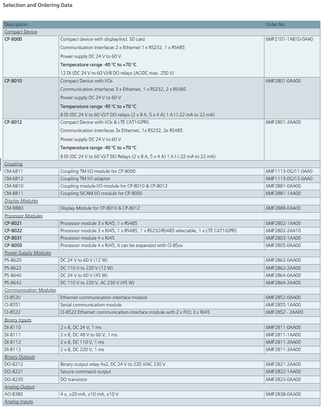
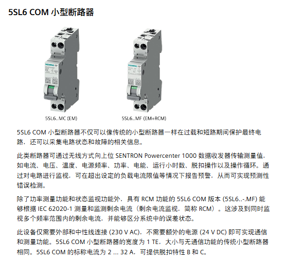
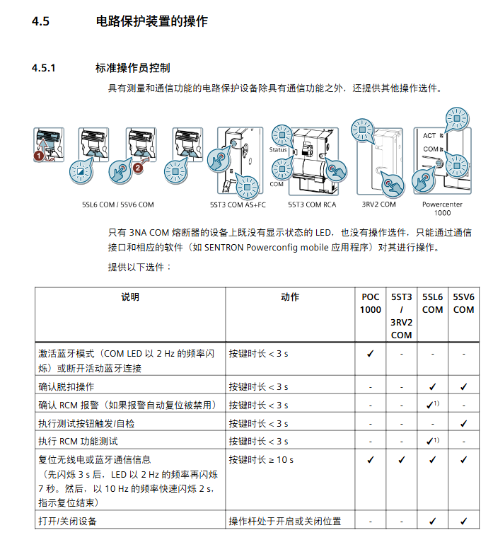
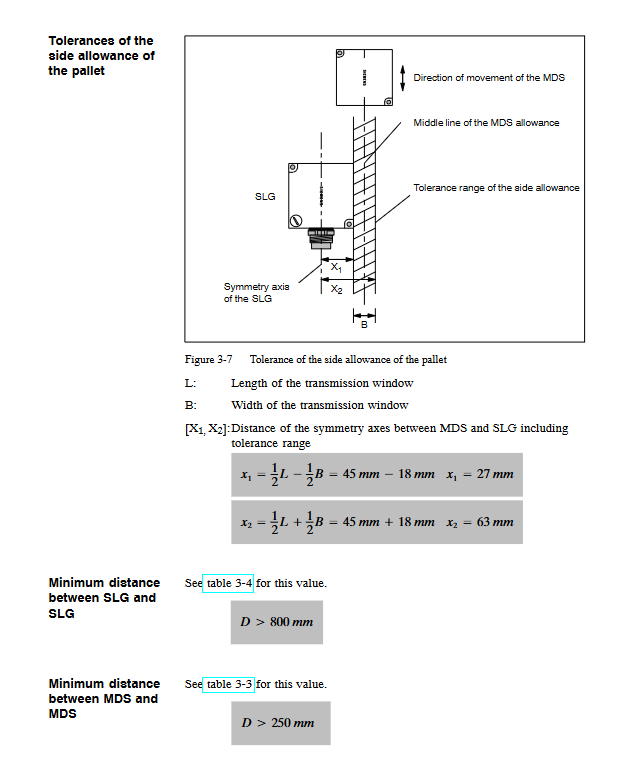
Siemens SIPROTEC 4 series protective relay
The core products of Siemens SIPROTEC 4 series protective relays (including models such as 7SJ61/62/64/66) cover multiple protection functions such as overcurrent, distance, and differential, and support multi protocol communication such as IEC 61850/IEC 60870-5-103. They have flexible protection configuration, synchronous switching, fault recording, and positioning characteristics, and are suitable for multiple scenarios such as medium and high voltage power grids, motors, transformers, and busbars. Combined with DIGSI 4 engineering software and SIGRA fault analysis tools, they can achieve full lifecycle protection, control, and monitoring.
Overview of Product System
1. Product classification and core models
Product Type Core Model Core Function Applicable Scenarios
Overcurrent protection relay 7SJ61 for non directional overcurrent, ground fault, motor protection circuit, motor, and transformer backup protection
7SJ62 direction overcurrent, flexible protection (20 group expansion), voltage/frequency protection for complex circuits, dual power supply
7SJ64 synchronization function, CFC expansion programming, fault location automation substation, multi switch control
7SJ66 Local Control, Multi Interface Communication, Local Protection for Small and Medium sized Substations
Distance protection relay 7SA522/6 series phase to phase/ground distance protection, power oscillation lockout transmission line, long-distance cable
Differential protection relay 7SD52/53/610 line differential, multi terminal differential short line, cable line
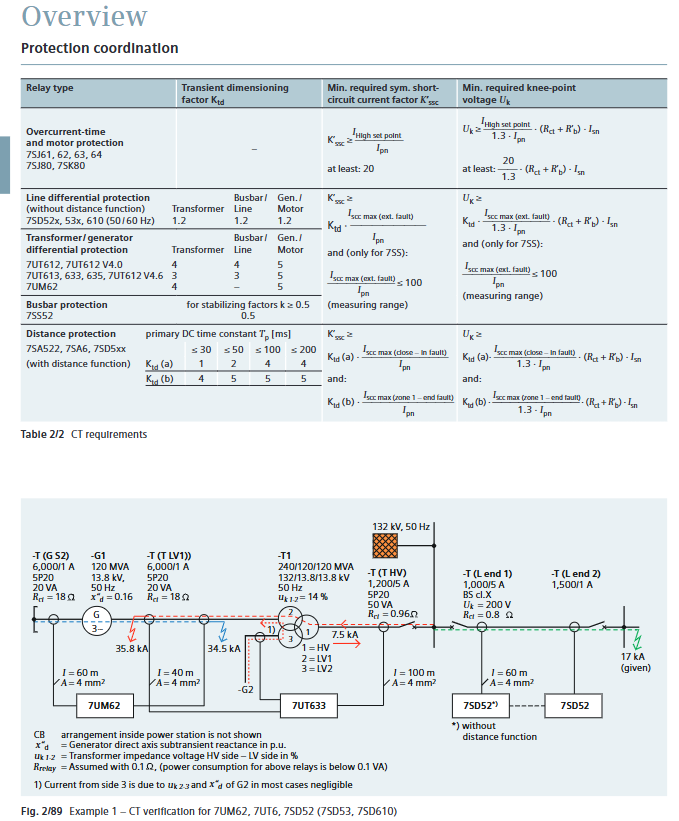
7UT612/613 Transformer/Generator Differential, Ratio Braking Transformer, Generator Transformer Unit
7SS52 distributed busbar differential, circuit breaker failure protection busbar protection, complex wiring method
Other specialized relays 7UM62 for comprehensive protection of generator and transformer units, demagnetization/step loss protection for generators and transformer units
7VK61 circuit breaker management, end fault protection circuit breaker control, breaker-a-half wiring
2. Core advantages
Function integration: Single device integration of protection, control, measurement, and diagnostic functions, supporting the principle of “one feeder, one relay”.
Flexible Expansion: 7SJ62/64 supports 20 sets of flexible protection functions, and can customize trigger logic such as current/voltage/power.
Safe and reliable: Complies with standards such as IEC 60255 and ANSI C37.90, and has self-monitoring and trip circuit monitoring functions.
Open compatibility: Supports multi protocol communication and is compatible with Siemens SICAM systems and third-party control platforms.
Detailed introduction of core functions
(1) Protection function
1. Basic protection function
Protection type core parameters/characteristic representative model
Overcurrent protection with definite/inverse time characteristics (ANSI/IEC standard), supporting cold load pickup for the entire range of 7SJ products
Ground fault protection sensitive type (minimum 0.001A), intermittent, directional, suitable for different grounding methods 7SJ62/64, 7SD series
Overload protection thermal model calculation (IEC 60255-8), supporting environmental temperature compensation 7SJ61/62/64
Automatic reclosing up to 9 times (1 fast+8 delayed), phase separation/three-phase reclosing 7SJ61/62/64
2. Special protection function
Synchronization related: synchronous inspection (voltage/frequency/phase difference monitoring), synchronous/asynchronous switching (considering circuit breaker mechanical delay), supporting 4 sets of parameter storage.
Equipment specialization:
Motor protection: Start time monitoring, locked rotor protection, restart lockout, bearing temperature monitoring (up to 12 sensors).
Transformer protection: excitation surge suppression (second harmonic braking), high impedance limited grounding fault protection.
Generator protection: demagnetization, stepping loss, reverse power, stator grounding (third harmonic) protection.
(2) Control and Automation
1. Control function
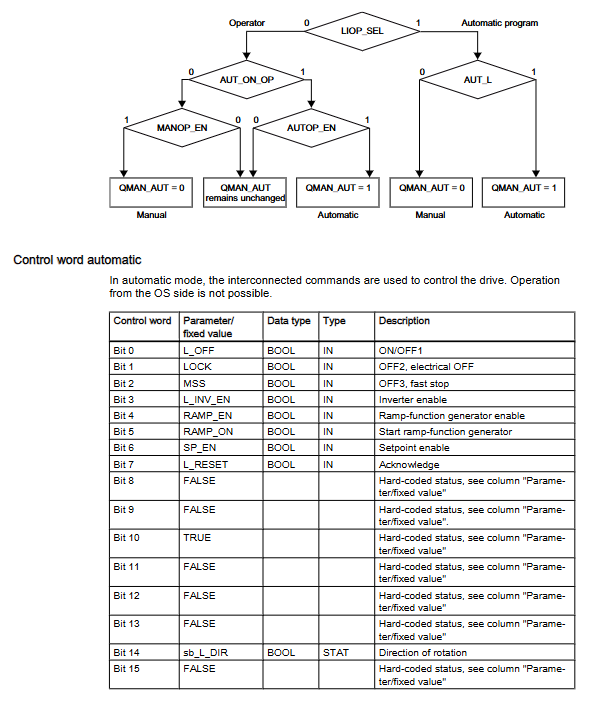
Switch control: Supports local (panel/button) and remote (SCADA/DIGSI 4) control of circuit breakers, isolating switches, and grounding switches, and supports single/dual command processing.
Permission management: Switch the priority of permissions to “LOCAL>DIGSI 4>REMOTE”, and support key switch to switch between local/remote modes.
Interlocking function: Implement equipment interlocking (such as checking the position of the isolation switch before closing the circuit breaker) and switching sequence control through CFC programming.
2. Logic Programming (CFC)
No programming experience required, custom functionality can be achieved by dragging and dropping logic components (and/or/triggers/timers).
Support threshold judgment of measurement values, signal logic combination, user-defined alarms, and command output.
(3) Monitoring and Diagnosis
1. Measurement and recording
Measurement parameters: three-phase current/voltage, zero sequence component, active/reactive power, power factor, frequency, electrical energy (± kWh/± kVarh), supporting maximum/minimum value recording.
Fault record: Up to 8 sets of fault waveforms (including analog/switch values), event logs store the last 8 faults, with a timestamp accuracy of 1ms.
2. Status monitoring
Circuit breaker management: supports three wear calculation methods: ∑ I ^ x, ∑ I ² t, and two-point method, and can set wear limit alarms.
Loop monitoring: Trip loop monitoring (ANSI 74TC), which monitors the status of the trip coil through 1-2 binary inputs.
Motor statistics: Record key data such as startup frequency, startup time, running time, and shutdown time.
Supporting tools and communication
1. Core supporting tools
Tool Name Core Function Key Features
DIGSI 4 project configuration, parameter settings, CFC programming support one-time/two-way value switching, routing matrix configuration, 30 day trial version
SIGRA 4 fault waveform analysis supports 6 chart types, multiple waveform synchronization, and COMTRADE format import
The IEC 61850 System Configurator supports cross vendor configuration of IEC 61850 devices, supporting SCL file import and export, and is compatible with Ed1/2.0/2.1 versions
2. Communication capability
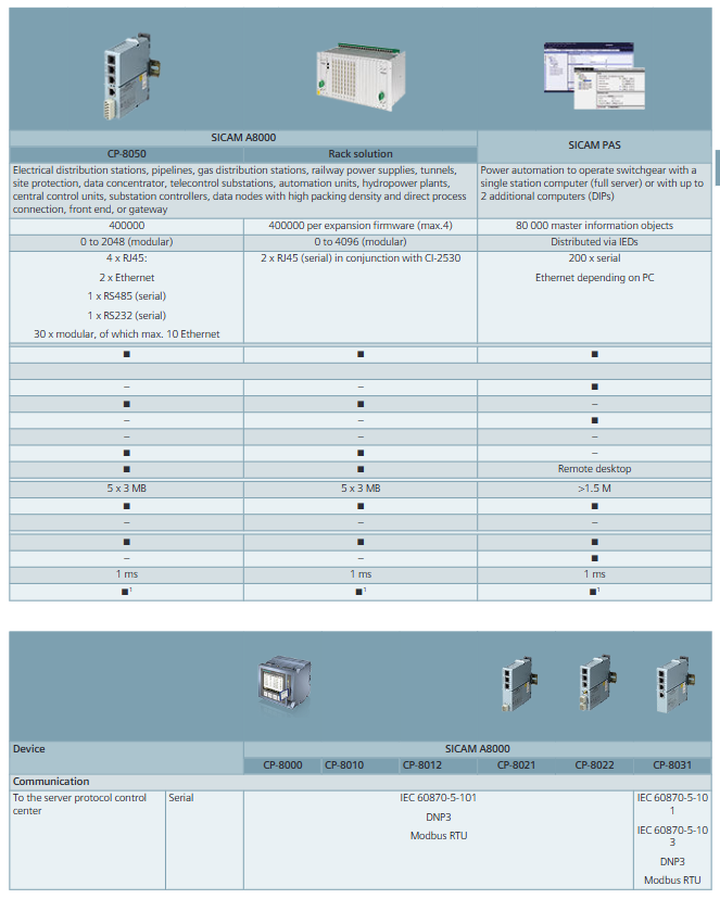
Supporting protocols: IEC 61850 (Ethernet) IEC 60870-5-103、PROFIBUS DP、MODBUS RTU、DNP 3.0/DNP3 TCP、PROFINET IO。
Communication topology: RS485 bus (up to 31 devices), fiber ring network (anti-interference), Ethernet redundancy (RSTP/PRP/HSR).
Remote access: Supports modem/Ethernet remote access, web server monitoring (some models).
Installation and Technical Parameters
1. Installation requirements
Installation method: 19 inch rail installation, shell width 1/3~1/2 rack (244mm standard height).
Wiring specifications: The current terminal supports 2.7-4mm ² wire, the voltage terminal supports 0.5-2.5mm ² wire, and supports ring terminal/direct connection.
Environmental adaptation: Working temperature -25 ℃~+70 ℃, humidity 5% -95%, no condensation, altitude up to 6000m (with capacity reduction required).
2. Key technical parameters
Core indicators of parameter categories
Current circuit rated current 1A/5A, overload capacity 20A continuous, 500A/1s
Voltage circuit rated voltage 100V~225V, power consumption<0.3VA/phase
Auxiliary voltage DC 24-250V, AC 115-230V, ripple tolerance ≤ 12%
Binary input 8-11 channels, response time ≈ 3.5ms, voltage threshold switchable
Binary output 4-8 channels, switching capacity 30A/0.5s (current on)
Typical application scenarios
Recommended Application Object Model Core Protection Configuration
Radiation type line 7SJ61/62 overcurrent+ground fault+automatic reclosing
Directional overcurrent+fault location+interlocking control for ring network line 7SJ62/64
Transformer 7UT612/613+7SJ80 differential protection+backup overcurrent+high impedance grounding protection
High voltage motor (>1MW) 7UM62/7SJ64 overload+locked rotor+negative sequence+temperature monitoring
Bus protection 7SS52 distributed differential+circuit breaker failure protection
Generator transformer set 7UM62 demagnetization+out of step+reverse power+stator grounding protection
