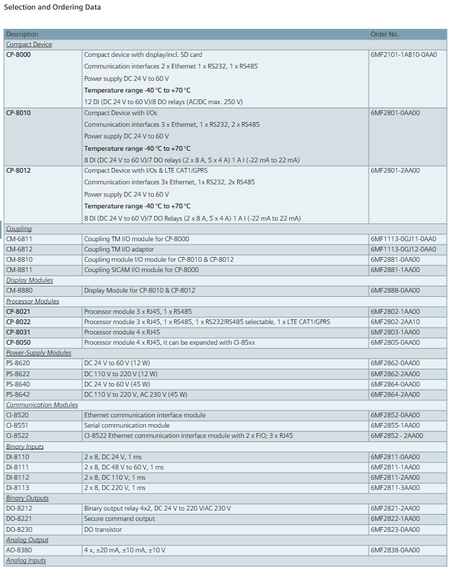
Call us 24/7uaedcs@163.com
Welcome to the official website of CNIACS Automation Technology Co., Ltd!
Call us 24/7uaedcs@163.com

GE IS230 Series Industrial Managed Layer 2 Switches

Overview

The Allied Telesis IS230 Series is a  multipurpose product line of managed Layer 2 switches ideal for industrial applications, including manufacturing, rail transportation (telecommunication and signaling), road transportation (traffic control), and Smart Cities.

With fanless operation and a wide operating temperature range of -40° to 75°C, the robust IS230 Series easily tolerates harsh and demanding environments, such as those found in industrial and outdoor deployments.

An integrated voltage regulator ensures the PoE output voltage always stays at the rated value, regardless of any fluctuations in the input voltage of powered devices. An extended input voltage range makes the IS230 Series ideal for deployment in traffic control cabinets.

Network resiliency

The IS230 Series supports highly stable and reliable ICT network switching, with recovery times down to 50ms. The IS230 can be customized with the most appropriate mechanism and protocol to prevent network connection failure.

Choices include Allied Telesis Ethernet

Protection Switched Ring (EPSRing™), and the standards-based ITU-T G.8032.

Securing the Network Edge

Ensuring data protection means controlling network access. Protocols such as IEEE 802.1X port-based authentication guarantee that only known users are connected to the network. Unknown users who physically connect can be segregated into a pre-determined part of the network. This offers network guests Internet access, while ensuring the integrity of private network data.

Quality of Service

Comprehensive wire-speed QoS provides flow-based traffic management with Port/Tag Base and Type of Service prioritization. Bandwidth control limits ingress/

egress traffic and broadcast/multicast/flooded unicast packets.

Gigabit and Fast Ethernet support

The IS230 Series offers combo ports supporting both Gigabit and Fast Ethernet Small Form-Factor Pluggables (SFPs). Support for both SFP types allows organizations to stay within budget even as they migrate to faster technologies.

Configurable power budget

On PoE-sourcing IS230 switches, all LAN ports source POE+ up to 30W.

You can configure both the overall power budget and the power feeding limit on a per-port basis, to establish a close relationship between the power sourcing feature and the real capabilities of the external Power Supply Unit (PSU)1.

Dual power inputs

The IS230 Series provides redundant power inputs for higher system reliability; the power inputs are protected against reverse polarity and over-current.

ECO friendly

The IS230 Series are Energy Efficient Ethernet (EEE) devices. They facilitate power saving by switching off parts of the LAN that are not transmitting or recieving data. This sophisticated feature can significantly reduce operating costs, by reducing the

power requirements of the switch and any associated cooling equipment.

Key Features

Full Gigabit, wire speed ports

Uplink combo ports

100/1000Mbps SFP support

Flexible management interface (GUI, SNMP, CLI, TELNET and SSH)

Ethernet Protection Switched Ring (EPSRing™)

Ethernet Ring Protection Switching (ITU-T G.8032)

VLAN stacking (Q-in-Q)

Multicast support (IGMP and MLD snooping)

Loopback detection and storm control

Port mirroring

Port trunking/link aggregation (LACP)

Link Layer Discovery (LLDP)

IEEE 802.3at PoE+ sourcing (30W)

-40 to +75oC wide-range operating temperature

Dual power inputs with voltage boost converter

Alarm output

Fanless design

Performance

Up to 8K MAC addresses

Packet buffer memory: 512KB (4Mb)

8 priority QoS queues

4094 configurable VLANs

256 simultaneous VLANs

Supports 9KB jumbo frames

Up to 255 Layer 2 multicast entries

Environmental Specifications

Operating temperature range: -40°C to 75°C (-40°F to 167°F)

Storage temperature range: -40°C to 85°C (-40°F to 185°F)

Operating humidity range:

10% to 95%RH non-condensing

Storage humidity range:

10% to 95%RH non-condensing

Operating altitude

3,000m maximum (9,843ft)

Mechanical

EN 50022, EN 60715 Standardized mounting  

on rails

Environmental Compliance

RoHS

China RoHS

WEEE

Ordering Information

Switches

The DIN rail and wall mount kits are included.

AT-IS230-10GP-80

8x 10/100/1000T, 2x 100/1000X SFP combo, Industrial Layer 2 Switch, POE+ support (120W)

Supported SFP Modules

Refer to the installation guide for the recommended Max.

Operating Temperature according to the selected SFP module.

1000Mbps SFP Modules

AT-SPBD10-13

10 km, 1G BiDi SFP, LC, SMF (1310Tx/1490Rx)

AT-SPBD10-14

10 km, 1G BiDi SFP, LC, SMF (1490Tx/1310Rx)

AT-SPBD20-13/I

20 km, 1G BiDi SFP, SC, SMF, I-Temp

(1310Tx/1490Rx)

AT-SPBD20-14/I

20 km, 1G BiDi SFP, SC, SMF, I-Temp

(1490Tx/1310Rx)

AT-SPBD40-13/I

40 km, 1G BiDi SFP, LC, SMF, I-Temp

(1310Tx/1490Rx)

AT-SPBD40-14/I

40 km, 1G BiDi SFP, LC, SMF, I-Temp

(1490Tx/1310Rx)

AT-SPEX

2 km, 1000EX SFP, LC, MMF, 1310 nm

AT-SPLX10

10 km, 1000LX SFP, LC, SMF, 1310 nm

AT-SPLX10/I

10 km, 1000LX SFP, LC, SMF, 1310 nm, I-Temp

AT-SPLX40

40 km, 1000LX SFP, LC, SMF, 1310 nm

AT-SPSX

550 m, 1000SX SFP, LC, MMF, 850 nm

AT-SPSX/I

550 m, 1000SX SFP, LC, MMF, 850 nm, I-Temp

AT-SPZX80

80 km, 1000ZX SFP, LC, SMF, 1550 nm

100Mbps SFP Modules

AT-SPFX/2

2 km, 100FX SFP, LC, MMF, 1310 nm

AT-SPFX/15

15 km, 100FX SFP, LC, SMF, 1310 nm

AT-SPFXBD-LC-13

15 km, 100FX BiDi SFP, LC, SMF

(1310 Tx/1550 Rx)

AT-SPFXBD-LC-15

15 km, 100FX BiDi SFP, LC, SMF

(1550 Rx/1310 Tx)

GE IC693TCM302/303 Temperature Control Module

Module core functions and general characteristics

The functional framework of the two TCM modules is consistent, with only differences in temperature range and resolution. The core capabilities include:

Control mode: Supports two operating modes: Open Loop and Closed Loop, suitable for different temperature control scenarios.

Channel configuration: It can achieve temperature control for up to 8 channels, each equipped with thermocouple input interface and relay output interface, and supports RTD (resistance temperature detector) input.

Voltage compatibility: Equipped with 12V common mode voltage capability, suitable for signal transmission needs in industrial scenarios.

Fault detection: supports automatic detection and reporting of two types of critical faults——

Thermocouple faults: including open circuit (Open) and reverse circuit (Reverse) faults;

Temperature anomaly: Detect and report temperature deviations that exceed the tolerance range.

Hardware Connection and Interface Description

The module is connected to external devices through two pairs of matching “plug-in connectors” with captive screw terminals for easy on-site wiring. The specific interface division is as follows:

Interface type, location, connection object, key terminal identification

Input connector module left thermocouple (8 channels, corresponding to 1+-1- to 8+-8- terminals), RTD (R+, R -, S+, S – terminals) – Channel input: 1+-1- to 8+-8- (each channel’s positive and negative terminals correspond to a thermocouple)

-RTD inputs: R+, R -, S+, S – (compatible with RTD sensors)

Output connector module right side relay (8 channels, corresponding to 1+-1- to 8+-8- terminals), external power supply (P+, P – terminals) – channel output: 1+-1-~8+-8- (each channel positive and negative terminal corresponds to a relay)

-External power supply: P+(positive pole), P – (negative pole, supplying power to the output relay)

-Grounding: G terminal (grounding connection)

In addition, there is an internal fuse located behind the front cover of the module for circuit overload protection. The specific parameters are “2 Amp, 125V ultra small fuse” (recommended model: Littlefuse Microfiuse 273 002 or equivalent).

Meaning of LED status indicator light

The front of the module is equipped with 6 types of LED indicator lights, which provide feedback on device operation and fault information through on/off/flashing status. The specific instructions are as follows:

Meaning and Status Explanation of LED Identification Colors

P (External Power) green – normal state: constantly on, indicating that the module has been connected to an external power source;

-Abnormal state: Off, possibly due to a blown internal fuse.

R (Run) green – normal status: constantly on, indicating that the module is running normally;

-Abnormal state: The red F (Fault) LED flashes alternately, indicating an internal fault in the module.

F (Fault) red – normal state: normally off;

-Startup phase: flashing (module executing internal startup program);

-Abnormal state: The green R (Run) LED flashes alternately, indicating an internal fault in the module.

S (Short) red – normal state: normally off;

-Abnormal state: illuminated, indicating a short circuit fault in one of the output circuits.

1-8 (Output Status) Green – Function: Corresponding to 8 output channels, the indicator light on/off ratio reflects the PWM (Pulse Width Modulation) cycle of that channel;

-Example: LED 8 corresponds to the channel to which the 8+and 8- terminals of the right connector belong, and the on/off rhythm is synchronized with the channel output adjustment.

Automatic data exchange with PLC

The module and the CPU of Series 90-30 PLC achieve control and status feedback through “automatic data transmission”, without the need for manual triggering. Each PLC sweep completes a data exchange, and the specific data flow is as follows:

1. PLC → TCM (Control Instruction Transmission)

PLC sends control instructions to TCM through% Q bit (digital output) and% AQ word (analog output), and the core instructions include:

Enable/Disable Output;

Control mode switching (Auto/Manual Mode);

Do Autotuning trigger;

Setpoint values transmission (target temperature);

Alarm Limit Values (temperature alarm upper and lower limits) transmission.

2. TCM → PLC (status information feedback)

TCM provides feedback on the operating status to PLC through the% I bit (digital input) and% AI word (analog input), with core information including:

Alarm status (such as over temperature alarm);

Output Short Circuit status;

Current Temperature (real-time temperature of each channel);

PWM period (the pulse period output by each channel);

TCM Error Code (locate specific fault type).

Core differences between TCM302 and TCM303

The two modules only differ in “temperature measurement range” and “resolution”. TCM303 is the “extended range version”, and the specific parameter comparison is as follows:

Comparison item IC693TCM302 IC693TCM303

J-type and L-type thermocouples have a temperature range of 0-450 ° C to 0-750 ° C

K-type thermocouple temperature range 0-600 ° C 0-1050 ° C

Resolution 12 bits/0.2 ° C (i.e. minimum temperature detection accuracy of 0.2 ℃) 12 bits/0.5 ° C (i.e. minimum temperature detection accuracy of 0.5 ℃)

Precautions for replacing fuses

When the P (External Power) LED goes out and the fuse is suspected to be blown, the following steps must be followed to replace it, and safety regulations must be followed:

Turn off the PLC power first, and then remove the TCM module;

Use a small standard screwdriver (pocket size) to loosen the side card of the front cover and gently pull the cover outward;

Use pointed nose pliers to pull out the old fuse from the front of the module and replace it with a fuse of the same specification (2A, 125V);

Warning: It is strictly prohibited to use fuses that do not meet the specifications, otherwise it may cause personal injury or equipment damage.

MKS 979B Atmosphere to Vacuum Transducer

Product basic information

Product model: 979B (atmospheric pressure to vacuum sensor), part number 100014647

Safety and General Specifications

1. Safety warnings and preventive measures

Electrical safety: When replacing sensors or baking, the power supply must be disconnected first (there may be fatal voltage/current), and only qualified technicians can operate electronic components; Use+24 VDC@0.75 Amps power supply, ensure that the sensor is grounded through the vacuum flange and electrical connector rear housing.

Operation restriction: Do not turn on the filament power supply when the system pressure is higher than 5 × 10 ⁻ Torr (which may damage the hot cathode sensor); Prohibited from use in explosive/flammable gas environments (hot cathode heating elements, MicroPirani’s nickel film elements may ignite gases); Do not replace parts or modify equipment. Repairs must be sent to the MKS calibration service center.

Pollution protection: prevent dust, metal shavings and other pollutants from entering the equipment; During installation, stay away from electronic/ion sources and strong magnetic fields. If necessary, use a particulate filter (see “Accessories” section for details).

2. General technical specifications

Specific project parameters

Measurement range 5 × 10 ⁻¹⁰ Torr to atmospheric pressure (ATM)

Set point range 5 × 10 ⁻¹⁰ Torr to 100 Torr

Analog output DAC1: 0.5-6.95 VDC (0.5 V/order of magnitude); DAC2: 0.75-10.02 VDC (0.75 V/order of magnitude)

Overvoltage limit of 1500 Torr

Repeatability (typical value) 1 × 10 ⁻⁹ -10 ⁻³ Torr: ± 5% reading; 10 ⁻ -100 Torr: ± 2% reading

Accuracy (typical value) 10 ⁻⁹ -10 ⁻³ Torr: ± 20% reading; 10 ⁻ -100 Torr: ± 5% reading

Supply voltage 24 VDC ± 10%

Power consumption 15 Watts

Rated value of relay contacts 1A@30 VAC/VDC (resistive load), compliant with Semi 52/UL991 safety standards

Vacuum contact material 304 stainless steel, silicon, SiO ₂, SiN ₄, gold, fluororubber (Viton) ®)、 Glass, tungsten, platinum molybdenum plating, yttrium oxide coated iridium, epoxy resin, Kovar alloy

Shell material aluminum/304 stainless steel

Internal volume 23 cm ³

Working temperature 0-40 ℃

Baking temperature (non working state) 85 ℃

Installation direction in any direction

EU certification complies with EMC Directive 89/336/EEC (EN-61326-1) and Low Voltage Directive 73/23/EEC (EN-61010-1)

Vacuum connection methods Mini CF, 2.75 “CF, NW16 KF, NW25 KF, NW40 KF

Size (with KF25) 74 × 79.6 × 100 mm (2.9 “× 3.1” × 3.9 “)

Weight (with KF25) 422 g (0.93 lbs.)

Installation Guide

1. Installation position and direction

Location selection: It is necessary to be able to accurately measure the pressure in the vacuum chamber, away from the pump and gas source to ensure representative readings; Avoid installing directly above the evaporation source (steam may contaminate the sensor), and shield and stay away from strong magnetic fields when approaching electronic/ion sources.

Installation direction: Supports installation in any direction, it is recommended that the vacuum port face downwards (to prevent particles/liquids from entering), which does not affect measurement accuracy.

2. Vacuum connection

The sensor offers multiple flange types: 2.75 “CF (rotatable), 1.33” CF (rotatable) KF16、KF25、KF40, Corresponding flanges need to be matched according to the system, and the manual provides dimension drawings of each flange for reference.

3. Electrical connection

Cable requirements: Use a 15 pin high-density D-sub female cable with strain relief; To meet the anti-interference requirements of EN61326-1, braided shielded cables are required, with metal hooks connected at both ends of the shielding layer and the power supply grounded.

Pin function: The 15 pin D-sub connector has clear pin division, and the core pins include: 1 pin (RS485-/RS232 TXD), 2 pins (RS485+/RS232 RXD), 3 pins (power+24V), 4 pins (power -), 5 pins (analog output+), 6 pins (analog output -), 9 pins (degassing state), 10 pins (filament selection), 13 pins (degassing on), as well as the common terminals (7, 11, 14 pins) and normal terminals (8, 12, 15 pins) of 3 relays. For details, please refer to the “979B Sensor Electrical Connection Table”.

Attention: The negative terminal (6-pin) of the analog output should not be connected to the negative terminal (4-pin) of the power supply or other grounding points (which may cause current diversion and measurement errors, and the longer the cable, the greater the error); When connecting inductive loads (such as solenoids and transformers), an arc extinguishing network (resistor R and capacitor C) needs to be installed. The calculation formula is

C=I 2/(1 × 10 7) (Farads), R=E/I a (ohms, where a=1+(50/E)), and R is at least 0.5 Ω and C is at least 1.0 × 10 ⁻⁹ F.

Operation control

1. Control and status pin operation

Degassing on (Pin13): Enable degassing when grounded, with priority higher than DG command or degassing button; After 30 minutes of degassing, it is necessary to disconnect and reconnect to restart degassing, and degassing should not exceed 30 minutes every 4 hours.

Degassing state (Pin9): When degassing is closed, it is open circuit/suspended, and when it is open, it is grounded; An external pull-up resistor with ≤ 24 VDC can be connected, and the current should be less than 15mA.

Filament selection (Pin10): By switching the active filament on/off the power supply, the state can be switched instead of selecting a fixed filament.

2. Factory default settings

The sensor parameters are preset to default values, including: active filament 1, address 253, baud rate 9600, degassing power off, automatic emission current (20 μ A>1 × 10 ⁻⁴ Torr, 1mA<1 × 10 ⁻⁴ Torr), control set point enabled, filament power off, gas correction 1, gas calibration type nitrogen, 3 set points disabled, hysteresis value 1.10E0 Torr, set point value 1.00E0 Torr, set point direction “below (BELOW)”, protection set point 1.0E-2 Torr, unit Torr, analog output DAC1, RS485 test off, RS delay on.

3. RS-485/RS-232 communication protocol

Basic parameters: Supports baud rates of 4800-112200 (default 9600), data format of 8-bit data bits, no checksum, and 1-bit stop bit; RS-485 is a half duplex two-wire system, which is the same protocol as RS-232.

Address rule: Standard address 001-253 (default 253); Universal address 254 (used for communication with unknown address devices, will respond), 255 (broadcast address, executes commands but does not respond, such as batch modification of baud rate).

Command syntax: The query format is @<device address><query command>?; FF (such as querying baud rate: @ 253BR?)?; FF), The command format is @<device address><command instruction>! <Parameters>; FF (such as changing the baud rate to 19200: @ 253BR! 19200; FF); The response starts with ACK (success) or NAK (failure), and the NAK code corresponds to different errors (such as 160=unrecognized message, 169=invalid parameter, 172=value out of range, etc.).

4. Core Command Set

The commands are divided into five categories: setting, status, pressure measurement and degassing, set point, and calibration. The core commands are as follows:

Command Type Command Identification Function Description Example

Set command AF (active filament) to query/select 2 filaments (value 1/2) of the hot cathode sensor. Query: @ 001AF?; FF; Setting: @ 001AF! 2; FF

AD (Address) Query/Set Device Address (001-253) Query: @ 254AD?; FF; Setting: @ 001AD! 002; FF

BR (baud rate) query/set baud rate (4800/9600, etc.) query: @ 001BR?; FF; Setting: @ 001BR! 19200; FF

DAC (Analog Output) Query/Set Analog Output Type (1=DAC1, 2=DAC2) Query: @ 001DAC?; FF; Setting: @ 001DAC! 2;FF

FD (factory default) restores all user calibration values to factory default command: @ 001FD!; FF

Status command DT (device type) query device type response: @ 001ACKMP-HC 979B; FF

FS (filament status) query for the on/off status of the active filament: @ 001FS?; FF

FV (firmware version) query firmware version response: @ 001ACK1.00; FF

SN (serial number) query device serial number response: @ 001ACK0000012345; FF

T (sensor status) query hot cathode status (F=filament fault, G=hot cathode on, etc.) Response: @ 001ACKO; FF (O=normal)

Pressure measurement and degassing FP (filament power supply) switch filament power supply (only effective when the control setpoint is disabled, disabled when the pressure is greater than 5 × 10 ⁻ Torr) command: @ 001FP! ON; FF

DG (degassing power supply) switch degassing (pressure must be<1 × 10 ⁻⁵ Torr, automatically shuts off after 30 minutes) query: @ 001DG?; FF; Setting: @ 001DG! ON; FF

PR1/PR2/PR3 (pressure readings) respectively read MicroPirani (PR1, above 1 × 10 ⁻³ Torr), hot cathode (PR2, below 1 × 10 ⁻⁴ Torr), and combined reading (PR3, full range). Query: @ 001PR1?; FF; Response: @ 001ACK1.23E-2; FF

The set point command SPx (set point value) queries/sets the pressure values (Scientific notation) of the three set points: @ 001SP1! 1.00E-3; FF

SDx (Setpoint Direction) Query/Set Setpoint Direction (BELOW/ABOVE) Setting: @ 001SD1! ABOVE; FF

SHx (hysteresis value) query/set the set point hysteresis value (to avoid relay jitter and match direction) setting: @ 001SH1! 1.10E-3; FF

ENx (Enable Setpoint) Enable/Disable 3 Setpoint Commands: @ 001EN1! ON;FF

Calibration command ATM (atmospheric pressure calibration) to calibrate MicroPirani to full range (requires ventilation to atmospheric pressure, stable for 20 minutes) Command: @ 001ATM! 7.60E+2; FF

VAC (vacuum calibration) calibration MicroPirani zero point (needs to be drawn to<1 × 10 ⁻⁴ Torr, stabilized for 20 minutes, automatically calibrated when hot cathode pressure<1 × 10 ⁻⁴ Torr) command: @ 001VAC!; FF

GT (gas type) query/setting MicroPirani’s measurement gas (nitrogen/air/argon, default nitrogen) setting: @ 001GT! ZEROGEN; FF

GC (gas correction) query/set gas correction coefficient for hot cathode (0.10-50.1, default 1, such as argon 1.29) setting: @ 001GC! 1.29; FF

Analog output and gas correction

1. Simulation output calculation and table

DAC1: Pressure calculation formula P=10 (2V − 11) (Torr), the manual provides a detailed voltage correspondence table for 1.0E-10 Torr (0.50V) to 1.0E+03 Torr (7.00V).

DAC2: Pressure calculation formula P=10 0.75 V − 7.75 (Torr), also provide a complete pressure voltage correspondence table.

2. Gas correction factor

MicroPirani is based on gas thermal conductivity measurement, and the hot cathode is based on gas ionization measurement, both of which need to be corrected according to the gas type:

Gas chemical formula gas correction factor (GC)

Air -1.00

Argon gas Ar 1.29

Carbon dioxide CO ₂ 1.24

Deuterium gas D ₂ 0.35

Helium He 0.18

Hydrogen H ₂ 0.46

Krypton gas Kr 1.94

Neon gas Ne 0.30

Nitrogen N ₂ 1.00

Nitric oxide NO 1.16

Oxygen O ₂ 1.01

Sulfur hexafluoride SF ₆ 2.50

Water H ₂ O 1.12

Xenon Xe 2.87

Maintenance and troubleshooting

1. Daily maintenance

Cleaning: The casing can be cleaned with water or alcohol to prevent liquids from entering the electronic casing; The sensor tube must not be cleaned (as it may damage the components), and the sensor needs to be replaced in case of severe contamination.

Degassing operation: When the hot cathode sensor is contaminated by process gas (especially when the sensitivity drifts when the pressure is ≤ 10 ⁻⁸ Torr), regular degassing is required; When degassing, the pressure should be less than 1 × 10 ⁻⁵ Torr. During this period, the pressure can be measured but the reading may be higher than the system pressure. When the pressure is greater than 1 × 10 ⁻⁴ Torr, degassing is paused and restarted after reaching the threshold. It will automatically terminate after 30 minutes, and degassing should not exceed 30 minutes every 4 hours.

2. Common faults and solutions

Possible causes/solutions for the fault phenomenon

RS-485/RS-232 no response 1. Missing starting character @; 2. Address error (you can try @ 254; FF query); 3. Missing termination character; FF; 4. Baud rate mismatch; 5. Missing/incorrect electrical connections

MicroPirani reading too high/too low/

Syco Tec 4061 AC Motor Spindle

Product core positioning and application scenarios

1. Core positioning

The 4061 motor spindle is a high-speed precision spindle driven by three-phase asynchronous drive. It adopts an integrated design, integrating the motor, bearings, clamping system, and protective structure. It is suitable for industrial processing scenarios with strict requirements for speed and accuracy. It can be directly mounted on machine tools or automation equipment to achieve efficient cutting and forming of workpieces.

2. Typical applications

Processing types: drilling (Bohren), milling (Fr ä sen), grinding (Schleifen), carving (Graviren);

Applicable industries: precision machinery manufacturing, electronic component processing, mold manufacturing, medical device parts processing, etc;

Suitable for workpieces: small and medium-sized precision parts such as metal, non-metal (such as plastic, composite materials), etc.

image.png

Key technical parameters

1. Basic performance parameters

Parameter category, specific specifications, remarks

Clamp diameter (Spandurchmesser) 60mm is used to fix the connection size between the spindle and the equipment

Motorart: A mature and stable driving method for three-phase asynchronous motors, suitable for industrial inverters

Speed range (Drehzahlbereich) 5000-50000 min ⁻¹ (conventional); 60000 min ⁻¹ (short-term) High speed is suitable for temporary high-intensity processing, and attention should be paid to the load duration

Power supply parameter voltage (Spanung): 230V; Current (Strom): maximum 7A; Frequency: 83-833Hz (conventional), 1000Hz (short-term). The frequency is positively correlated with the speed and needs to be adjusted with an adaptive inverter

Maximum torque output performance (Drehmomont): 80Ncm; Maximum power (Leistung): 1400W to meet the power requirements of medium and light precision machining

The precision index (Rundlauf) has a typical value of 1 μ m and high rotational accuracy, ensuring smooth surface and precise size of the processed workpiece

2. Structure and protection parameters

Specific specifications and functions of parameter categories

Lagerung bearing system consists of 3 sets of ceramic bearings (3 x Keramik) with lifetime lubrication (lebensdauergeschmiert). Ceramic bearings have strong wear resistance and low heat generation, extending the life of the spindle without the need for regular oil replenishment

Protection level (Schutzart) IP54 dustproof (completely preventing dust intrusion), splash proof (no damage from splashing in any direction), suitable for workshop processing environment

Motor protection (Motorschutz) PTC temperature protection (triggered at 100 ℃) automatically protects when the motor temperature exceeds 100 ℃ to prevent overheating and damage

The shell material (Geh ä usematerial) is made of stainless steel (Edelstahl), which is corrosion-resistant and impact resistant, suitable for long-term exposure to cutting fluids or dust

Anti pollution design seal gas protection (Sperrlft): 0.5-0.8 bar, compatible with 4/6mm inner and outer diameter hoses to prevent dust and cooling lubricants from entering the spindle during processing, protecting bearings and motors

3. Clamping and cooling parameters

Specific specifications and details of parameter categories

The clamping range of the chuck (Spanzangenbereich) is Ø 1.0-6.35mm (including standard specifications of 1/8 inch and 1/4 inch), suitable for common specifications of cutting tools (such as milling cutters and drill bits), meeting the needs of multi scene machining

Tool Replacement (Werkzeugwechsel) Pneumatic Drive (Pneum.), pressure 5-6 bar, compatible with 4/6mm flexible hose for quick automatic tool change, improving machining efficiency and reducing manual intervention

The cooling system (K ü hlsystem) is cooled by a clamping bracket (K ü hlung durch Einspannvorrichtung) using the device’s own clamping structure to conduct heat, without the need for additional cooling fans or water cooling devices, simplifying the structure

Supporting requirements and installation instructions

1. Essential supporting equipment

Inverter (Umrichter): Recommended model is e @ syDrive ®  4438 TV 4538, Need to match the voltage and frequency range of the spindle to adjust the speed and output power;

Pneumatic system: Tool replacement requires 5-6 bar compressed air, anti pollution requires 0.5-0.8 bar sealed air, and the air source must be stable, oil-free, and water free;

Connecting cables: The product does not include cables. Please refer to page 37 of the document to select the appropriate specifications (such as wire diameter and insulation level) to ensure stable and safe power supply.

2. Installation and usage restrictions

Load direction (Belastungsrichtung): Supports axial and radial loads, can withstand multi-directional machining forces, but needs to avoid overloading operations beyond the torque/power limit;

Work position (Gebrauchslab): No special restrictions, can be flexibly installed according to equipment layout (such as horizontal, vertical, inclined);

Maintenance requirements: The bearings are designed for lifelong lubrication and do not require regular maintenance; Regularly check the sealing gas pressure and clamp clamping accuracy to prevent machining quality from being affected by insufficient air pressure or clamp wear.

image.png

Emerson DeltaV Electronic Marshalling Migration Solution

Core positioning and value of the solution

1. Core Definition and Function

DeltaV electronic grouping is a “flexible I/O architecture” technology that replaces traditional hard wired terminal cabinets with CHARactration Modules and Electronic Marshalling Cabinets to achieve a “soft connection” between field device signals (analog/digital input/output) and DeltaV controllers – without the need to lay a large number of field cables, signal routing can be allocated through configuration software, and the core service is for the migration scenario of old DCS systems.

2. Core migration value

Compared to the traditional migration model of “dismantling old systems and rebuilding new systems”, the core advantages of this solution are reflected in the three dimensions of “cost reduction, risk reduction, and efficiency improvement”:

Reduce downtime: Support “parallel migration” – while the old system is running normally, complete the installation, configuration, and testing of the new system’s electronic grouping architecture, with only a brief shutdown at the final switch (usually in hours, rather than days/weeks of traditional migration).

Reduce hardware and wiring costs: eliminate the need for replacing/laying a large number of on-site cables in traditional migration (especially suitable for large factories, where on-site equipment is far away from control rooms); The electronic grouping cabinet has a smaller volume, reducing the footprint of the control room.

Enhance system flexibility and maintainability: Signal routing is implemented through software configuration, and there is no need to rewire when adding/modifying devices in the future; The CHAR module supports online hot plugging, and fault replacement does not affect other signals; Integrated diagnostic function can quickly locate signal faults (such as disconnection and short circuit).

Compatible with legacy devices: No need to replace existing sensors and actuators on site (such as 4-20mA analog devices and discrete digital devices), directly adapt to old device signal types, and protect early investment.

Core components and technical parameters

1. Core hardware components

The hardware architecture of the DeltaV electronic grouping solution consists of three parts: “field side grouping side controller side”. The core components and functions are as follows:

Component Name Model/Specification Core Functions Key Features

The CHAR module (signal interface module) is divided into analog (AI/AO), digital (DI/DO), and special signal (such as RTD, thermocouple) series, such as:

-AI module: supports 4-20mA, 0-10V, etc

-DI module: supports the “conversion interface” between 24Vdc, 120Vac discrete signal field equipment signals and DeltaV systems, realizing signal acquisition/output, isolation, and filtering. 1. Channel level isolation (each channel is independently isolated to prevent interference);

2. Online hot plugging (replacing modules without interrupting system operation);

3. Built in diagnostics (monitoring channel faults, module power supply abnormalities);

4. Protection level IP20 (applicable to control room/cabinet environment)

Electronic grouping cabinet standard 19 inch rack mounted, height optional (such as 42U, 36U), including power module, backplane, integrated CHAR module for heat dissipation unit, power distribution, signal aggregation function, replacing traditional hard wired terminal cabinet. 1. Modular design (configure the number of CHAR modules as needed);

2. Redundant power supply (optional 2 × 24Vdc redundant power supply, anti power failure);

3. Backplane bus (supporting data communication and power supply between modules);

4. Heat dissipation control (built-in fan or natural heat dissipation, suitable for industrial environments)

DeltaV S series controllers (such as S100, S200) receive signal data from electronic grouping modules, execute control logic (such as PID regulation, interlock control), and output control instructions to the site. 1. Redundant configuration (optional controller redundancy to improve reliability);

2. High speed communication (communication with electronic grouping cabinets through EtherNet/IP, cycle ≤ 10ms);

3. Compatible with DeltaV V14 and above software versions

On site wiring terminal box (optional) explosion-proof type (such as Ex d) or ordinary type, used for summarizing and transferring cables of on-site equipment. When the on-site equipment is scattered, the cables are first summarized in the terminal box and then connected to the electronic grouping cabinet through a “backbone cable” to reduce wiring volume. 1. Support mixed access of multiple signal types;

2. Explosion proof models are suitable for hazardous areas (such as Class I, Div 1/2)

2. Key technical parameters (general)

Signal compatibility:

Analog input (AI): 4-20mA (two-wire/four wire system), 0-5V, 0-10V, RTD (Pt100, Cu100), thermocouple (J, K, T, E, R, S type);

Analog output (AO): 4-20mA (sourcing/linking), 0-10V;

Digital input (DI): 24Vdc (wet/dry contact), 120Vac, 230Vac;

Digital output (DO): 24Vdc (maximum 0.5A/channel), relay output (250Vac/5A).

Communication protocol: EtherNet/IP protocol is used between the electronic grouping cabinet and the controller, supporting high-speed data transmission (communication rate 100Mbps full duplex); The module adopts DeltaV dedicated backplane bus internally.

Power requirements: The power supply for the electronic grouping cabinet is 24Vdc (± 10%), and the maximum power consumption of a single cabinet depends on the number of modules (typical value: power consumption of each CHAR module ≤ 5W).

Environmental conditions:

Working temperature: 0 ℃~55 ℃ (cabinet environment);

Storage temperature: -40 ℃~70 ℃;

Relative humidity: 5%~95% (without condensation);

Anti electromagnetic interference: Complies with EN 61000-6-2 (industrial environment immunity) standard.

Security certification:

Electrical safety: UL 61010-1, CSA C22.2 No. 61010-1;

Electromagnetic compatibility (EMC): EN 61326-1 (industrial environment);

Hazardous area certification (some components): ATEX, IECEx (applicable to Zone 2/Class I, Div 2).

Migration process and applicable scenarios

1. Standard migration process

The DeltaV electronic grouping migration follows a “four stage” implementation framework to ensure parallel operation and smooth switching with the old system:

Planning and Evaluation Stage

Evaluate the I/O signal types, quantities, cable routing, and control logic of old systems such as RS3 and WDPF;

Determine the number and installation location of electronic grouping cabinets (usually near old terminal cabinets to reduce cable modifications);

Develop a migration schedule (distinguishing between “non critical circuits” and “critical circuits”, prioritizing the migration of non critical circuits).

Installation and configuration phase

Install electronic grouping cabinets, CHAR modules, and on-site wiring terminal boxes (if necessary) while the old system is running normally;

Connect the on-site cable to the CHAR module (without disconnecting the old system wiring, dual system signal acquisition can be achieved through “T-shaped wiring” or parallel wiring);

Configure signal routing in DeltaV software (mapping CHAR module channels to DeltaV controller I/O points) and import old system control logic (supporting logic conversion tools).

Testing and Verification Phase

Conduct offline testing on the migrated circuit (simulate on-site signals to verify the correctness of control logic);

Conduct online parallel testing (both the old and new systems receive on-site signals simultaneously, compare the output results, and ensure consistency);

Perform multiple rounds of validation on critical circuits such as emergency shutdown system ESD and reactor temperature control to ensure no deviation.

Switching and optimization phase

Select non peak production hours to “switch” a single circuit or area (disconnect the old system wiring and be controlled separately by the new system);

Continuously monitor the operating status of the system after switching, and use DeltaV diagnostic function to identify potential faults;

After completing the full system migration, dismantle the old system hardware and optimize the new system parameters (such as control algorithms and alarm thresholds).

2. Applicable migration scenarios

This solution is not applicable to all DCS migrations, and the core matches the following scenarios:

The old system is a hard wired DCS, such as Fisher Rosemount RS3, Westinghouse WDPF, Honeywell TDC 3000 and other old systems without flexible I/O architecture;

Industries with high downtime costs, such as refining, ethylene, LNG, and other continuous production processes, can experience significant economic losses due to long downtime caused by traditional migration;

The on-site equipment is in good condition: the on-site sensors and actuators are still within their service life and do not need to be replaced (if the equipment has aged, it can be implemented synchronously with “equipment update+electronic grouping migration”);

Limited space in the control room: The electronic grouping cabinet has a smaller volume and is suitable for scenarios where there is insufficient expansion space in the control room.

Not applicable scenario: The old system is a fully digital architecture (such as systems that have already adopted Profinet and Foundation Fieldbus); All on-site equipment needs to be replaced (it is more economical to directly use the new DeltaV system at this time).

System advantages and competitive differences

1. Core advantages (vs traditional migration)

Comparison Dimension DeltaV Electronic Grouping Migration Traditional Hardwired Migration

Short downtime (hourly level, only shutdown during switching stages) Long downtime (several days/weeks, complete system dismantling and reconstruction)

Low wiring cost (no need to re lay on-site cables, only need to connect between cabinets) High (all on-site cables need to be replaced, especially long-distance circuits)

High flexibility (software configuration signal routing, no wiring required for subsequent changes) Low flexibility (fixed hardware wiring, rewiring required for changes)

Low risk control (parallel operation, phased migration, can be rolled back to the old system at any time) High (one-time switching, no rollback path for faults)

Low maintenance cost (module hot plugging, integrated diagnosis, fast fault location) and high (complex troubleshooting of hard wired faults, requiring point by point testing)

2. Differences from other electronic grouping schemes

Compared to competitors such as Rockwell PlantPAx electronic grouping and Siemens PCS 7 Distributed I/O, the uniqueness of the DeltaV solution lies in:

Deep integration of DeltaV ecosystem: The CHAR module is seamlessly compatible with DeltaV controllers and software (such as DeltaV Operate and DeltaV Explorer), without the need for third-party adaptation tools;

Strong adaptability of legacy system: providing dedicated migration tools for Emerson’s old systems (such as RS3), which can automatically convert control logic and I/O databases, reducing manual configuration workload;

More comprehensive diagnostic functions: The CHAR module supports “channel level fault diagnosis” (such as disconnection, overcurrent, signal drift), and uploads diagnostic information in real time to the DeltaV alarm system without on-site inspection.

Barber Colman MA41-7153-502 and similar series actuators

Product core positioning and series differences

1. Core functions and applications

Purpose: Used for the “on-off” control and fail safe (power-off spring reset) operation of air doors and valves in HVAC systems, supporting direct coupling installation, and some models can be connected in parallel (linkage installation) to meet high torque requirements.

Key feature: Mechanical spring reset (clockwise/counterclockwise optional), ensuring reliable reset after power loss; 95 ° rotation stroke (can be limited by accessories to 30 ° -95 °); Visual position indicator; Overload protection during full rotation process; Some models come with built-in auxiliary switches for signal interaction or interlock control.

2. Differences in Series Models

The three major series are distinguished by torque level, voltage specifications, and additional functions, with the following core differences:

Series torque levels (lb in/N-m) voltage specifications core features auxiliary switch configuration manual override function

MA40-704X 35 (4) 24Vac/DC, 120Vac, 230Vac NEMA 2/IP54 protection (no installation restrictions), travel limiter standard with some models (-501) including 1 SPDT switch (0-95 ° adjustable) none

MA4X-707X 60 (7) 24Vac/DC, 120Vac, 230Vac NEMA 2/IP54 protection (requires downward installation of conduit), supports rotation restriction part models (-502) including 2 SPDT switches (1 fixed at 5 °, 1 adjustable at 25-85 °) MA41-707X series has (-5 ° to 85 ° adjustable)

MA4X-715X 133 (15) 24Vac/DC, 120Vac, 230Vac, same as MA4X-707X, with maximum torque, can be installed in parallel with two machines. Some models (-502) include two SPDT switches (one fixed at 5 ° and one adjustable at 25-85 °). The MA41-715X series has (-5 ° to 85 ° adjustable)

MA41-7153-502 Exclusive Attributes: Belonging to the MA4X-715X series, powered by 24Vac/DC, 133lb in (15N-m) torque, including 2 SPDT auxiliary switches, with manual override function, supporting dual machine parallel connection.

Key technical parameters

1. Electrical parameters

Specific specifications for parameter categories (taking MA41-7153-502 as an example, refer to Table 1 for other models)

Supply voltage 24Vac ± 20% or 22-30Vdc

Power consumption operation: 9.8VA (50Hz), 9.7VA (60Hz); Maintain: 7.5VA (50/60Hz)

Current running DC current 0.29A; locked rotor current 2.8A

2 SPDT auxiliary switches, resistive load 7A at 250Vac, inductive load 2.5A

Control signal single pole single throw (SPST) control contact or bidirectional thyristor (500mA rated)

Wiring 3-foot (91cm) equipment cable, 1/2-inch conduit interface (equipped with AM-756 convertible M20 metric conduit)

2. Mechanical and environmental parameters

Rotation stroke: Maximum 95 °± 5 °, MA40-704X series comes standard with a travel limiter, MA4X-707X/715X requires AM-689 accessories to achieve 30 ° -95 ° adjustment.

Wind door shaft adaptation:

MA40-704X: Standard fixture supports ≤ 5/8 inch (15mm) circular axis or ≤ 1/2 inch (13mm) square axis; AM-710 accessories support ≤ 3/4 inch (19mm) circular shafts.

MA4X-707X/715X: Standard fixture supports ≤ 3/4 inch (19mm) circular axis or ≤ 1/2 inch (13mm) square axis; AM-687 accessories support circular shafts ≤ 1.05 inches (27mm) or square shafts ≤ 5/8 inches (15mm).

Protection level: MA40-704X is NEMA 2/IP54; MA4X-707X/715X is NEMA 1/IP30 (NEMA 2/IP54 when the conduit is facing downwards).

Environmental conditions: Operating temperature -22 ° F to 140 ° F (-30 ° C to 60 ° C); Storage/transportation temperature -40 ° F to 160 ° F (-40 ° C to 71 ° C); Humidity 15% -95% RH (non condensing).

Certification: UL 873, CUL (Canada), CE (compliant with EMC/Low Voltage Directive), C-Tick Australia.

Installation specifications and operating procedures

1. Preparation before installation

Personnel requirements: It must be operated by qualified professional technicians who are familiar with national/local electrical regulations.

Tools and accessories: Please bring your own # 8 sheet metal screws, 10mm wrench, 7/16 inch wrench, 1/8 inch hex wrench, and screwdriver; Select the corresponding fixture based on the shaft diameter (such as AM-710, AM-687), and the installation method for the long axis (≥ 3.5 inches/90mm) and short axis (<3.5 inches/90mm) is different.

Safety warning: Disconnect the power supply before installation to prevent electric shock; Avoid approaching strong electromagnetic interference sources such as contactors and large motors; It is prohibited to drill holes in the actuator body (there are 6 pre drilled holes under the labels on both sides for accessory installation).

2. Core installation steps (divided into series)

(1) MA40-704X series

Wind door positioning: Adjust the wind door to the normal position (the indicator indicates 0 ° when the normally closed wind door is closed, and 0 ° when the normally open wind door is open), and confirm the direction of shaft rotation (clockwise/counterclockwise opening).

Fixture installation: For short shafts (<3.5 inches), the air door position indicator should be installed first, then the actuator should be inserted and the fixture nut should be manually tightened; Insert the long axis directly into the actuator and manually pre tighten the fixture.

Fixing and Calibration: After aligning the centerline, drill a hole to fix the bracket, loosen the clamp nut, rotate the actuator 5 ° in the direction of operation (without moving the shaft), then tighten the clamp nut with a torque of 4-6lb ft (5.4-8.2N-m), and finally fix the bracket screw.

(2) MA4X-707X/715X series (including MA41-7153-502)

The basic steps are the same as MA40-704X, but please note:

The conduit interface needs to be installed facing downwards to meet IP54 protection requirements;

MA41-707X/715X series with manual override: In the power-off state, use an Allen wrench to adjust the indicator to 0 ° and lock it. After installation, it will automatically unlock when powered on for the first time;

The tightening torque of the fixture is 8-10 lb ft (11-14 N-m), which is higher than the MA40-704X series.

3. Special installation scenarios

Dual machine parallel connection (linkage installation): AM-673 bracket is required, and all actuator L2 wires are connected to the transformer common terminal and L1 wires are connected to the live wire, ensuring consistent polarity and total current not exceeding the rated value of the transformer and control circuit.

Long axis/short axis adaptation: For shaft lengths ≥ 3.5 inches (90mm), use the long axis installation method; When using the short axis method for spaces smaller than 3.5 inches or when the space is narrow, an additional position indicator needs to be adapted.

Wiring and Debugging

1. Wiring specifications

Voltage corresponds to line color: 24Vac/DC model (such as MA41-7153-502) L1=red, L2=black; 120Vac model L1=black, L2=white; 230Vac model L1=brown, L2=light blue (see Table 2 and Table 5 for details).

Auxiliary switch wiring: The two switches of MA4X-715X-502/MA4X-707X-502 are respectively “5 ° fixed” (purple/yellow/orange line) and “25-85 ° adjustable” (purple white/yellow white/orange white line), used for indicating the position of the air door end and interlocking the fan start.

Wiring requirements: Class 2 control/power lines should be wired separately from line voltage lines and non-Class 2 circuits; The auxiliary switch line needs to be connected to a Class 1 circuit.

2. Debugging and Inspection

Power on test: After power on, the actuator should drive the air door to the “power on position”, and after power off, the spring should be reset to the “normal position”. Repeat the test 3 times to confirm reliability.

Auxiliary switch verification: For models with suffix -501/-502, manually adjust the switch pointer to the target angle and power on to verify whether the on/off status of the switch meets the requirements.

Rotation limit verification: If installing AM-689 (MA4X series) or using the built-in stroke limiter of MA40 series, it is necessary to test whether the rotation angle of the air door meets the design value (such as 45 °, 60 °) by powering on.

Operations and troubleshooting

1. Maintenance requirements

Daily maintenance: The actuator is designed to be maintenance free and does not require regular maintenance under normal use (in compliance with environmental and installation requirements). It only needs to be checked regularly by an electrician according to EN standards for the overall system status.

Manual override use: Only available in the MA41-707X/715X series. To operate when power is off, insert an Allen wrench into the override hole and rotate it to the target angle (-5 ° to 85 °). It is strictly prohibited to use it when powered on or in parallel with two machines (to avoid gear damage).

2. Troubleshooting

Possible causes and solutions for the fault phenomenon

Not functioning after power on: 1. The power supply is not properly connected or the voltage does not match; 2. The control contacts are not closed; 3. The fixture is too tight and stuck. 1. Check the wiring and voltage (e.g. 20-28Vac is required for 24Vac); 2. Confirm the continuity of SPST contacts; 3. Loosen the clamp nut and recalibrate the torque

1. Failure to reset due to power loss. Spring damage; 2. The air door is stuck; 3. The position of the rotation limiter is incorrect. 1. Replace the actuator; 2. Check the mechanical resistance of the air door; 3. Adjust the position of the limiter again

Auxiliary switch has no signal. 1. Wiring error; 2. The switch pointer is not aligned with the target angle; 3. The switch is damaged. 1. Check the wire color and wiring diagram; 2. Adjust the pointer again after power failure; 3. Replace the actuator

3. Disposal and Warranty

Scrap disposal: Metal, plastic, and electronic components must be disposed of in accordance with local regulations and can be returned to Barber Colman (shipping costs borne by the sender).

Warranty policy: The entire series is covered by a 5-year warranty, and damages caused by human factors (such as drilling or manual override during power on) are not covered by the warranty.

Key accessories and document references

1. Common accessories (adapted by series)

Adaptation series accessories, models, and purposes

MA40-704X AM-710 universal fixture compatible with ≤ 3/4 inch (19mm) circular shaft

MA40-704X AM-709 position indicator combined with travel limiter

MA4X-707X/715X AM-687 is compatible with fixtures for circular shafts ≤ 1.05 inches (27mm) or square shafts ≤ 5/8 inches (15mm)

MA4X-707X/715X AM-689 rotation limiter (adjust travel from 30 ° to 95 °)

Full series AM-673 dual machine parallel (linkage installation) bracket

Full series AM-756 M20 metric conduit to 1/2 inch NPT interface adapter

BARTEC MODEX PROFIBUS 07-7331-2305 Series

Module core information and functional differences

Both modules are PROFIBUS-DP interface devices with “4-channel digital output+8-channel digital input”. The core difference lies in the explosion-proof level of the output terminal. The specific comparison is as follows:

Comparison item model 07-7331-2305/000 model 07-7331-2305/1000

Output explosion-proof level Ex e (increased safety type) Ex i (intrinsic safety type)

Output voltage U2-0.2V (approximately 23.8V when U2 is 24V) DC 22V (when U2 ≥ 24V)

Single channel maximum output current 500mA-

Single channel internal resistance -301 Ω

Module loss power maximum 3.5W maximum 4.5W

Control object: 4-channel Ex e valve, 4-channel Ex i valve

Common core functions:

Input function: 8-channel Ex i intrinsic safety input, supporting NAMUR limit switches, mechanical contacts (compliant with EN/IEC 60947-5-6 standard), with wire breakage/short circuit detection;

Display function: Real time display of power supply (ON light), bus communication (BF light), status fault (SF light), output power supply (U2 light), and activation/fault status of each channel through LED;

Safety design: Short circuit protection (automatically cuts off output in case of short circuit), reverse polarity protection, supports cutting off actuator power through U2 terminal external emergency stop switch;

Communication and diagnosis: Connected to the control system through PROFIBUS-DP, it can transmit user data and diagnostic data (output disconnection/short circuit status), supporting SYNC (output status freeze) and FREEZE (input status freeze) functions.

Explosion proof certification and compliance

The module is designed for explosive hazardous environments and has passed multiple international certifications to meet compliance requirements in different regions

Certification System Certification Number/Directive Explosion proof Identification/Key Requirements

ATEX PTB 97 ATEX 1066 U, T Ü V 98 ATEX 1355 X II 2 (1) G Ex db e [ia Ga] IIC Gb; I M2 Ex db e [ia Ma] I Mb

IECEx PTB 11.0082U、TUN 11.0024X Ex db e [ia Ga] IIC Gb; Ex db e [ia Ma] I Mb

Regional Compliance  CSA(2011-2484303U)、INMETRO(UL-BR 13.0397U)、EAC(RU C-DE.BH02.B.00005) CSA  Identification: A/Ex d e [ia] IIC Gb

EU directives ATEX 2014/34/EU, RoHS 2011/65/EU, EMC 2014/30/EU comply with EN 60079 series explosion-proof standards and EN 60529 protection standards

Special explosion-proof requirements:

The module is marked with a “U” symbol and needs to be installed in an enclosure that complies with EN/IEC 60079-0 standard and has a protection level of not less than IP54;

If the shell is of Ex e increased safety type, it must meet the electrical clearance and creepage distance specified in Table 1+2 of IEC/EN 60079-7.

Key technical parameters

1. Electrical parameters (general)

Power supply voltage: Electronic part (L+/L -) DC 24V (20-30V); Output section (U2+/U2-) DC 24V (20-30V, supports emergency stop);

Input parameters (Ex i): U ₀=11.8V, I ₀=31mA, P ₀=90mW, linear characteristics, external inductance/capacitance limits vary with explosion-proof level (e.g. Ex ia IIC, L ₀ maximum 47mH, C ₀ maximum 1.5 μ F);

Bus interface: RS485 (screw terminal), PROFIBUS-DP address set through rotary switch (01-99, effective after power failure);

Isolation design: Galvanic isolation is used between power supply, bus, circuit, output, and input.

2. Physical and environmental parameters

Protection level: Electronic module IP66, terminal IP20 (uncovered)/IP30 (covered);

Installation: Suitable for TH35 × 15 (7.5) standard guide rail (EN/IEC 60715), with any installation direction;

Size and weight: 170mm x 96mm x 102mm (width x height x depth), weight 2.1kg;

Environmental conditions: working/storage temperature -40 ℃~+60 ℃ (T4 temperature level), relative humidity 5% -95% (no condensation); Anti vibration (2g/7mm, 5-200Hz, 3-axis), anti impact (15g, 11ms, 3-axis).

3. Terminals and Connections

Terminal specification: 2.5mm ² multi strand wire, terminal screw M2.5 × 0.45mm, tightening torque 0.4Nm;

Grounding requirements: 1-2 grounding terminals should be installed on the right side of the module, and the PA terminal should be connected to the grounding terminal with a 2.5mm ² wire.

Installation and operation specifications

1. Installation requirements

Installation personnel: must have the qualification to install electrical equipment in explosive hazardous areas and have read and understood the instructions;

Preprocessing: Before installation, check that the module is clean and undamaged, there is a power outage, and adjacent live parts are protected;

Operation steps: Insert the module into the guide rail until the buckle makes a sound, and tighten the terminal screws with a torque wrench at 0.4-0.7Nm.

2. Debugging and troubleshooting

Pre debugging inspection: installation correctness, shell integrity, wiring compliance, address and baud rate settings;

Priority for troubleshooting: LED status (such as BF red light indicating bus fault, SF red light indicating short circuit or U2 power failure) → Wiring/terminal fastening → Address/baud rate → Bus terminal and jumper → System restart (required after address change).

3. Maintenance and disposal

Maintenance: No maintenance is required under normal use, and regular inspections by electricians are required according to EN/IEC 60079-17/19;

Repair: Self repair is prohibited, please contact BARTEC GmbH;

Disposal: Belonging to B2B equipment under the WEEE directive, it needs to be disposed of in accordance with local regulations and can be returned to BARTEC (with shipping costs borne by the sender), WEEE number DE 95940350.

Rockwell Automation 1794 Series FLEX I/O Digital Input Module

Product Overview and Installation Preparation

(1) Product Core Information

Functional positioning: The 1794 series module is a FLEX I/O digital input module used for collecting digital signals (such as sensor and switch status) in industrial automation systems. It is transmitted through Flexbus in conjunction with terminal bases and supports 2-wire/3-wire input devices. Different models correspond to different input channel numbers (8/16/32 channels).

Hardware composition: The module needs to be installed on the 1794 series terminal base (such as 1794-TB3, 1794-TB32, etc.), and the core components include Flexbus connectors (for communication with adjacent bases/adapters), locking mechanisms (fixed modules), key switches (for base configuration), and status indicator lights (yellow, corresponding to the signal status of each input channel).

(2) Preparation before installation

Compatibility confirmation: It is necessary to use a specified communication adapter to ensure normal functionality. For example, 1794-IB32/IB32K requires the use of Remote I/O 1794-ASB (E series and above), ControlNet 1794-ACN15 (C series, firmware 4.1 and above), etc; Programming requires the use of Studio 5000 Logix Designer V20 or higher versions.

Tools and materials: Prepare suitable screwdrivers (for fixing terminal base screws), anti-static tools (grounding wristbands, anti-static cloth), wires that meet specifications (referring to terminal base requirements, usually 22-14 AWG shielded copper wire), DIN rails (made of galvanized chromate passivated steel material to ensure good grounding and avoid poor conductors such as aluminum/plastic).

Environmental inspection: Confirm that the installation environment meets the requirements – pollution level 2 (industrial environment), overvoltage category II (EN/IEC 60664-1), altitude ≤ 2000 meters (no need to reduce capacity), and working temperature matching model (IB8/IB16 is -20~+55 ℃, IB32/IB32K is 0~+55 ℃).

Installation and wiring steps

(1) Module installation process

Base configuration: Rotate the key switch (position 3) on the terminal base to the “2” position (corresponding to the module type), ensuring that the Flexbus connector is fully pushed to the left and properly docked with the adjacent base/adapter.

Module alignment: Check if the pins at the bottom of the module are straight, align the alignment rod (position 6) of the module with the groove of the base (position 5), press the module evenly until the locking mechanism (position 2) clicks into the base, and confirm that the module is securely attached to the base.

Cleaning and inspection: During installation, avoid metal debris and wire residue from falling into the module to prevent short circuit damage after power on; After installation, check if all connections are secure and if the pins are not bent.

(2) Wiring method by model

1. 1794-IB8/IB16 (with 1794-TB3/TB3S base)

Wiring steps and operation details

Connect the signal line of the input device to the corresponding terminal of “A row (0-15)” (e.g. Input 0 is connected to A-0, Input 1 is connected to A-1)

Connect the+V DC power cord of the input device to the corresponding terminal of “C row (34-51)” (such as Input 0 connected to C-35), and all+V terminals in C row are internally connected; Connect the DC common terminal (3-wire device) to the corresponding terminal of “B row (16-33)” (such as Input 0 connected to B-17), and the B row common terminal is internally connected

Main power connection+V DC connection C-34, DC common terminal B-16

If the daisy chain extension needs to supply power to the next base, use jumper wires to connect the current base C-51 (+V) to the next base C-34, and B-33 (common terminal) to the next base B-16

2. 1794-IB32/IB32K (with 1794-TB32/TB32S base)

The module is divided into two sets of inputs (0-15, 16-31) and requires independent wiring:

Input 0-15: Connect the signal line to “A row (0-15)”,+V1 to C row 35/37/39/41, COM1 to C row 36/38/40/42;

Input 16-31: Connect the signal line to “B row (17-32, skip 16/33)”,+V2 to C row 43/45/47/49, COM2 to C row 44/46/48/50;

When expanding,+V1 jumps to the next base power terminal through C-41, and COM1 jumps to C-42; +V2 jumps through C-49, COM2 jumps through C-50.

(3) Wiring precautions

2-wire devices only need to connect the signal line and power line, while 3-wire devices require an additional connection to the common terminal;

The insulation layer of the wire needs to be stripped to a suitable length (to avoid short circuits caused by excessive exposure), and the torque of the terminal screws needs to meet the requirements of the base (usually 0.6-0.8 Nm);

Grounding needs to be achieved through DIN rails, which are fixed every 200 millimeters. End anchors need to be installed at both ends to ensure continuous grounding and low impedance.

Module configuration method

(1) Core configuration parameters

The module sets the input filtering time through the “configuration word (handwriting)”, and the memory mapping and filtering control bits are different for different models. The core adjusts the signal stability through the “input filtering time (FT)” to avoid interference and false triggering.

(2) Filter time setting

Filter time options: selected through 3 binary bits (FT0-FT2), default 0.25 ms, optional 0.5 ms, 1 ms, 2 ms, 4 ms, 8 ms, 16 ms, 32 ms (see Table 6 for specific correspondence).

Configuration position by model:

1794-IB8: The filtering control bit corresponds to the 0-2 bits of “Write 1” and controls all 8 input channels;

1794-IB16: Control Input 0-11 with 0-2 bits, Input 12-15 with 3-5 bits, and support counter function (Input 15 can be set as fast input/standard input, and needs to be configured through CF/CR bits);

1794-IB32/IB32K: The filtering control bit corresponds to bits 8-10 of “Write 1” and controls all 32 input channels.

Configuration example: If you need to set the filtering time of 1794-IB8 to 4 ms, you need to write binary “101” (corresponding to decimal 5) to the “Write 1” address at system startup to ensure that the filtering parameters take effect after the module is powered on.

Technical specifications and certification

(1) Core electrical specifications

Model Number of input channels Rated voltage Conducting current (typical) Turning off current (maximum) Isolation voltage Maximum power consumption

1794-IB8 8 (sinking type) 24V DC 8 mA 1.5 mA 50V DC (850V DC test for 60s) 3.5 W

1794-IB16 16 (sinking type) 24V DC 8 mA 1.5 mA 50V DC (707V DC test for 60s) 6.1 W

1794-IB32 32 (sinking type) 24V DC 4.1 mA 1.5 mA 50V DC (2121V DC test for 2s) 6.0 W

1794-IB32K 32 (sinking type) 24V DC 4.1 mA 1.5 mA 50V DC (2121V DC test for 2s) 6.0 W

(2) Environmental and mechanical specifications

Environmental parameters: working humidity of 5% -95% (no condensation), storage temperature of -40~+85 ℃, vibration (working) of 5 g @ 10-500 Hz (IEC 60068-2-6), impact (working) of 30 g (IEC 60068-2-27);

Mechanical parameters: Module size (with base) 94 × 94 × 69 mm (3.7 × 3.7 × 2.7 inches), weight 71-79 g, no shell (open type), relying on external shell protection.

(3) Compliance certification

The module has passed multiple international certifications to ensure compliant use worldwide, with core certifications including:

Safety certification: UL (Industrial Control Equipment, Class I Division 2 Hazardous Areas, USA/Canada), CSA, TUV (IB16 supports SIL 2 functional safety);

Electromagnetic compatibility (EMC): EN 61326-1, IEC 61000-6-2/4, in compliance with anti-interference and radiation requirements for industrial environments;

Dangerous Place Certification: ATEX (European Zone 2), IECEx (International Zone 2), UKEX (UK Zone 2);

Environmental certification: Compliant with the EU RoHS Directive (2011/65/EU) and China CCC Explosion proof Certification (CNCA-C23-01).

GE PCI5565 Multi Channel MIL-STD-1553 Interface Card

Product core positioning and application scenarios

(1) Positioning

PCI5565 is a high-performance MIL-STD-1553 interface card based on the PCI bus, designed to meet the MIL-STD-1553A/B standard (military data bus standard, used for reliable transmission of critical data in aviation electronics, spacecraft and other systems), supporting multi-channel and multi role 1553 bus communication (bus controller BC, remote terminal RT, bus monitor BM), with high stability and flexible scalability, suitable for scenarios with strict requirements for data transmission security and real-time performance.

(2) Typical applications

Avionics system: data exchange between avionics equipment of fighter jets and passenger planes (such as engine parameters, navigation information, and flight control system command transmission).

Space system: Communication of onboard equipment for satellites and spacecraft, data acquisition and command issuance for ground testing and control platforms.

Military ground equipment: internal and external data bus connections for radar systems, command and control systems, and weapon equipment testing platforms.

High reliability industrial control: Some industrial automation systems that require extremely high fault tolerance and anti-interference capabilities (such as key control modules in the energy and transportation fields).

Core functional characteristics

(1) 1553 bus communication capability

Multi channel and multi role support

Provide 2 independent 1553 channels, each channel can be flexibly configured as a bus controller (BC), remote terminal (RT), or bus monitor (BM) role, and each channel role can be independently set to meet the communication needs of multiple nodes in complex systems.

Supports multiple role combinations such as “BC+RT”, “Dual RT”, “BC+BM”, etc. A single channel can simultaneously achieve BM function (monitoring bus data) and BC/RT function (participating in data transmission).

Protocol and Data Processing

Fully compatible with MIL-STD-1553A/B standard, supporting all standard 1553 message formats (such as standardized transmission of command words, data words, status words), including special communication scenarios such as broadcast messages and mode code instructions.

Built in hardware level message processing engine, capable of automatically encoding/decoding 1553 messages, error detection (such as parity errors, format errors, bit errors) and correction, reducing CPU usage and ensuring real-time performance (message processing latency as low as microseconds).

Support message priority configuration, which can set high priority for critical data (such as emergency control instructions) to ensure their priority transmission.

(2) PCI bus interface characteristics

Compatible with PCI 2.2 standard, supports 32-bit data bus width, operates at a frequency of 33MHz, conforms to the interrupt request (IRQ) mechanism of PCI local bus specification, and is compatible with mainstream x86 architecture and embedded PCI motherboards.

Supports Plug and Play (PnP) functionality, which can automatically recognize hardware parameters (such as base address and interrupt number) through the system BIOS or driver program, simplifying the installation and configuration process.

(3) Hardware Enhancement and Reliability Design

Anti interference and fault tolerance capability

The 1553 bus interface adopts optocoupler isolation design (isolation voltage ≥ 2500Vrms), effectively suppressing electromagnetic interference (EMI) and radio frequency interference (RFI), reducing the impact of external noise on bus communication, and meeting military grade electromagnetic compatibility (EMC) requirements.

Built in bus fault detection and protection mechanism. When a bus short circuit, overload or abnormal signal is detected, the local circuit protection interface card and external bus devices can be automatically cut off. After the fault is restored, communication can be automatically restarted.

Storage and caching

Each 1553 channel is equipped with an independent message cache area (with a typical capacity of 64KB or higher), supporting pre storage and post reading of messages to avoid data loss caused by CPU response delay, especially suitable for high-throughput communication scenarios.

Support non-volatile storage (such as EEPROM), which can save user configuration parameters (such as channel roles, message formats, interrupt triggering conditions). The parameters will not be lost after the system is powered off and will be automatically loaded after restart.

(4) Software Support and Tools

Provide a complete driver package that supports Windows (XP/7/10), Linux (mainstream distribution), and VxWorks (embedded real-time operating system). The driver interface is compatible with industry standard APIs (such as GE specific API and MIL-STD-1553 universal programming interface), making it easy for users to quickly develop applications.

The supporting bus monitoring and configuration tool can display the real-time status of 1553 bus data transmission (such as message content, transmission rate, error statistics), support visual setting and saving of configuration parameters, and provide data logging function for system debugging and troubleshooting.

Detailed technical specifications

(1) Electrical specifications

Category parameter details

1553 bus parameters Bus type: MIL-STD-1553A/B, differential Manchester code

Data rate: 1Mbps (standard rate)

Bus load: Each channel supports up to 31 remote terminals (RTs)

Interface isolation: Optocoupler isolation, isolation voltage 2500Vrms (minimum)

Bus impedance: 50 Ω (terminal matching), supports external terminal resistance configuration

PCI bus parameter bus standard: PCI 2.2

Data width: 32 bits

Operating frequency: 33MHz

Power requirements:+3.3V DC (typical current 150mA),+5V DC (typical current 200mA)

Power consumption: maximum 5W

Other electrical characteristic interruption methods: PCI level triggered interruption

Logic level: TTL compatible (input high level 2.0V~5.5V, low level 0V~0.8V)

(2) Environmental specifications

Category parameter details

Temperature range: -40 ℃~+85 ℃ (wide temperature range, in compliance with military environmental requirements)

Storage temperature: -55 ℃~+125 ℃

Humidity working humidity: 5%~95% relative humidity (non condensing)

Storage humidity: 0%~98% relative humidity (no condensation)

Vibration and shock vibration (working): 10Hz~2000Hz, 10g acceleration (compliant with MIL-STD-883H Method 2026)

Impact (non working): 50g acceleration, 11ms pulse (compliant with MIL-STD-883H Method 2002)

Electromagnetic compatibility (EMC) radiated emissions: comply with MIL-STD-461F CE102 (conducted emissions), RE102 (radiated emissions)

Immunity: Complies with MIL-STD-461F CS101 (conducted sensitivity) and RS103 (radiated sensitivity)

(3) Mechanical specifications

Category parameter details

Form standard PCI low profile or full head card, compatible with standard PCI slots

Dimensions (Full height card) Length: 167.6mm (6.6 inches), Height: 106.7mm (4.2 inches), Thickness: 1.6mm (0.06 inches)

Interface connector 1553 bus: 2 DB-9 or Micro-D connectors (compliant with military connector specifications, optional gold-plated contacts)

PCI Bus: Standard PCI Gold Finger (32-bit)

Weight approximately 100g~150g (depending on specific configuration)

(4) Compliance and Certification

Compliant with military specifications such as MIL-STD-1553A/B (Military Data Bus Standard), MIL-STD-883H (Microcircuit Testing Standard), MIL-STD-461F (Electromagnetic Compatibility Standard), etc.

Through industrial level certification (such as CE, FCC), some models can provide special certification in the aerospace field (such as DO-160G, Aircraft Electronic Equipment Environmental Conditions and Testing Procedures).

Key points for hardware installation and configuration

(1) Installation requirements

Physical installation: The interface card needs to be inserted into a compatible PCI slot (32-bit, 33MHz), ensuring good contact between the gold finger and the slot, and tightening the fixing screws to prevent loosening caused by vibration.

Bus connection: The 1553 bus interface is connected to external 1553 devices through dedicated cables (such as twisted pair cables and shielded wires). Attention should be paid to the configuration of terminal resistors (50 Ω terminal resistors need to be connected at both ends of the bus, and there is no need to configure intermediate nodes) to avoid signal reflection.

Power requirements: Ensure that the motherboard PCI slot provides stable+3.3V and+5V power supply, with a maximum power consumption of no more than 5W, to avoid equipment failure caused by insufficient power supply.

(2) Configuration process

Driver installation: Install the matching driver program in the target operating system (such as Windows, Linux), and confirm that the hardware recognition is normal (no yellow exclamation mark) through the device manager.

Parameter configuration: Use supporting software tools to set 1553 channel roles (BC/RT/BM), message formats (data length, priority), interrupt triggering conditions (such as message reception completion, triggering interrupts during error detection), and other parameters, and save them to non-volatile storage.

Test verification: Send test messages through software tools, monitor the status of bus data transmission, check for errors (such as parity check errors, timeout errors), confirm communication is normal before connecting to the actual system.

Product advantages and competitive highlights

Multi channel high flexibility: Two independent 1553 channels support full role configuration, which can meet the communication needs of multiple nodes and tasks in complex systems without the need for additional interface cards.

Military grade reliability: wide temperature design (-40 ℃~+85 ℃), optocoupler isolation, EMC anti-interference ability, and fault protection mechanism ensure stable operation in harsh environments (such as high temperature, vibration, strong electromagnetic interference), meeting the strict requirements of military equipment.

Low CPU usage: The hardware level message processing engine reduces software intervention, lowers host CPU load, and ensures system real-time performance, especially suitable for embedded real-time operating system (such as VxWorks) environments.

Wide compatibility: compatible with mainstream operating systems and PCI motherboards, with accompanying software tools to simplify development and debugging, and reduce user application barriers.

Rockwell Automation 1757-SRM (B-series) module

Basic Information

The installation instructions for the redundant modules of the Rockwell Automation 1757-SRM series B-type ProcessLogix and ControlLogix systems are designed to guide users in installing the redundant module into the ProcessLogix or ControlLogix redundant chassis, covering the entire process of installation preparation, operation steps, fault handling, technical specifications, and more.

Important User Information and Security Standards

(1) Definition of Core Security Warning

The document specifies the meanings of different security signs to avoid operational risks, as follows:

Meaning of identification

Warning: Operating scenarios in hazardous environments that may cause explosions, resulting in personal injury, property damage, or economic loss

IMPORTANT annotation is crucial for the successful application and understanding of product information

Attention: Identify operational methods that may result in personal injury, property damage, or economic loss, and explain how to identify and avoid hazards and consequences

Labels on or inside SHOCK HAZARD equipment (such as drivers, motors) warning of hazardous voltage

Labels on or inside BURN HAZARD equipment (such as drives, motors) warning that the surface may reach dangerous temperatures

(2) Special environmental usage requirements

North American Hazardous Area Certification: Products marked as “CL I, DIV 2, GP A, B, C, D” are only applicable to Class I, Division 2, Groups A, B, C, D hazardous areas and non hazardous areas; When the system is used in combination, the overall temperature level must be determined by the temperature code with the lowest “T” number, and the equipment combination must be inspected by the local competent department.

European Hazardous Place Certification: Products marked with EEx comply with EU Directive 94/9/EC, are suitable for potentially explosive environments, must be installed in enclosures that meet at least IP54 protection level (Class I, Zone 2 environment), and can only be used in conjunction with ATEX certified backplates; At the same time, the device is not resistant to sunlight and other ultraviolet radiation, and transient interference should be prevented from exceeding the rated voltage by more than 40% in Class I Zone 2 environment.

General environmental requirements: Suitable for industrial environments with pollution level 2, overvoltage category II applications (compliant with IEC 60664-1), with no need for derating at altitudes up to 2000 meters (6561 feet); Belonging to Group A industrial equipment under the IEC/CISPR 11 standard, if appropriate protective measures are not taken, conducted and radiated interference may affect electromagnetic compatibility; The device is of an open design and needs to be installed in an enclosure that meets specific environmental requirements. The enclosure must have flame retardancy (non-metallic enclosures must reach 5VA, V2, V1, V0 or equivalent flame retardant levels), and the interior must be accessible with tools.

Module basic information and installation preparation

(1) Module core functions and appearance

Functional positioning: The 1757-SRM (B series) module is used for redundant control of ProcessLogix and ControlLogix systems, achieving communication and status synchronization between the primary and backup chassis through fiber optic connections, ensuring smooth switching in case of system failures.

Appearance structure: The front includes status indicator lights, fiber optic ports, and user relay terminals. These components are required to achieve module status monitoring, fiber optic connections, and external device control (such as relay linkage).

(2) Preparation before installation

Component List: Prepare 1756-A4/A7/A10/A13/A17 series chassis, 1757-SRM module, 1756-PA72/PA75/PB72/PB75 series power supply, and 1757-SRCxxx series fiber optic cable.

Static electricity protection: The module is sensitive to static electricity. Before operation, it is necessary to touch a grounded object to release static electricity and wear a certified grounding wristband to avoid touching the connectors/pins and internal circuit components of the component board. When idle, it should be stored in anti-static packaging and an anti-static workstation should be used when conditions permit.

Chassis and power pre-processing: The ControlLogix chassis and power supply need to be installed and connected first. Different models of chassis (such as 1756-A4/A7, etc.) and power supplies (such as 1756-PA72/C, 1756-PB72/B, etc.) should refer to the corresponding installation instructions (such as 1756-IN080, 1756-IN078, etc.).

Module slot selection: The recommended slot positions for different models of chassis are different. For example, slot 1 or 2 is recommended for the 1756-A4 chassis, and slot 4 or 5 is recommended for the 1756-A7 chassis. It is necessary to strictly install according to the recommended positions to ensure normal communication and redundancy functions.

Redundant system assembly steps

(1) Core installation process

Fiber optic cable connection: Before installing the module, connect one end of the 1757-SRCxxx series fiber optic cable (available in 1m, 3m, 10m, 50m, 100m specifications) to the fiber optic port of the module; If the distance between the main and backup chassis exceeds 100 meters, customized fiber optic cables must be used. The optical loss at a wavelength of 1300nm should be ≤ 7dB, and the length should be ≤ 4 kilometers (2.49 miles). 62.5/125 micron multimode fiber optic cables and professionally installed SC connectors should be used.

Module installation: Install the 1757-SRM module into the corresponding slots on the main and backup chassis (if the main chassis is plugged into slot 5, the backup chassis also needs to be plugged into slot 5); During installation, align the upper and lower rails of the chassis, slide the module in and ensure that the backplane connector is properly connected. When the module is aligned with other installed modules, it indicates that it is installed in place; When disassembling, press the locking clips on the upper right and lower left corners of the module, and then slide the module out.

Relay terminal wiring: If using a user relay, the wire needs to be threaded through the Steward 28A2029-0A0 model ferrite core (the core should be as close as possible to the end of the wire insulation layer), then connected to a detachable terminal block, and finally inserted into the relay terminal; The relay terminals must obtain external DC power from the same line as the SRM chassis power supply and comply with UL Class 2 (North America) or CE SELV/PELV (Europe) standards.

(2) Key operations of system configuration

Firmware upgrade: Data backup is required before upgrading (upgrading will overwrite old data), from the Rockwell Automation support website( http://support.rockwellautomation.com )Download the latest firmware and ControlFLASH firmware upgrade tool; Only supply power to one redundant chassis, wait for the module to display “FACT BOOT FLSH UPDT REQ”, start the upgrade tool to complete firmware installation, and after success, the module displays “PRIM”; Repeat the operation to upgrade another chassis module. If the upgrade is interrupted, the module will display “FACT BOOT FLSH UPDT REQ” or “USER BOOT FLSH UPDT REQ” after restarting the chassis, and a new upgrade is required.

Main chassis specification and system verification:

Main chassis designation: The chassis that is powered on first automatically becomes the main chassis, the module displays “PRIM” and the PRI indicator light turns green, and the normally open contacts of the relay are closed; If both chassis are powered on simultaneously, the chassis containing the module with the smaller serial number becomes the main chassis; The initial display of the backup chassis is “DISQ” or “SYNC”, the PRI indicator light is not on, and the normally open contact of the relay is disconnected.

System verification: After the main and backup chassis are powered on, automatic verification begins to verify the hardware and firmware compatibility of the main and backup modules. If the backup chassis displays “SYNC”, it indicates compatibility between configuration and firmware; If “DISQ” is displayed, it may be due to mismatched chassis configuration, inconsistent firmware versions, different Keeper parameters of ControlNet module, or MAC address not set to the same node address. The problem needs to be investigated and resolved.

Module status monitoring and fault handling

(1) Status indicator lights and display interpretation

Module status display (four characters):

When starting, displaying “Txxx” (xxx is the hexadecimal test number) indicates self-test;

“Indicates a transitional state;

DISQ “indicates that the backup chassis has not passed validation,” SYNC “indicates that the backup chassis has passed validation, and” PRIM “indicates the main chassis;

BOOT, ERAS, and PROG respectively represent boot mode (waiting for instructions), boot mode (erasing firmware), and boot mode (loading new firmware);

‘Exxx’ (xxx is an error/fault code) indicates a major malfunction and will alternately display fault information and error codes.

Health status indicator light:

Extinguished: The module is not powered on;

Always red: module self checks during startup or serious malfunction occurs;

Flashing red: The module is updating NVS, experiencing non critical faults, or configuring incorrectly;

Evergreen: The module is running normally;

Flashing green: The module is running normally but not communicating with other modules.

Inter module communication indicator light:

Extinguish: The module is not powered on or has no communication activity;

Red flash (<1 second): The module has been started and partner communication has been established;

Frequent red: serious communication failure occurs;

Green flash: There is communication activity (sampled every 250 milliseconds).

Chassis status indicator light:

Extinguish: The module is not powered on or the chassis is in standby/fault state;

Green flash (<1 second): Power on, partner module is determining the main state;

Evergreen: The chassis is in the main engine state.

(2) Fault type and handling

Fault classification:

Minor recoverable faults: do not affect redundant operations, modules may clear on their own;

Minor unrecoverable fault: does not affect redundant operations, but has no recovery mechanism;

Serious recoverable faults: affecting redundant operations (possibly not immediate), such as backup module failures that may affect control in the event of a host failure;

Serious unrecoverable fault: fatal fault, redundant operation stopped, possible switching, module replacement required.

Common faults and solutions:

|Fault code/display | Fault description | Handling measures|

|CFG LOG ERR | Configuration log error | No action required|

|COMM RSRC ERR | Communication resource error | Reset 1757-SRM module|

|COMM ERR PRT2 | Port 2 communication error (inter module link) | Check or replace 1757-SRCxxx fiber optic cable|

|FLSH UPDT REQ | Flash update required | Use corresponding firmware version to upgrade module|

|HDW ERR | Hardware Failure | Replace 1757-SRM Module|

|WDOG FAIL | Watchdog task status check failed | Replace 1757-SRM module|

Recovery instruction: The module displays “RPLC MOD” and needs to be replaced, “RSET MOD” needs to be reset, “REMV MOD” needs to be removed, and “SEAT MOD” needs to be reinserted.

Technical specifications

(1) Module core parameters

Category parameter values

Backplane current 3.3V DC 0.75A

5.1V dc 1.0A

24V dc 0.160A

Dimensions (height x width x depth) Standard ControlLogix chassis (2 slots wide) 14.5 x 7 x 14 centimeters (5.71 x 2.76 x 5.51 inches)

Weight – Approximately 0.452 kilograms (14.53 ounces)

Shell Protection Level – None (Open)

Temperature code IEC T4

North American T4A

Maximum power consumption -11.28W

Maximum heat dissipation -38.49 BTU/hour

Isolation voltage relay terminal to system for a continuous 30V, basic insulation type (853V AC test for 60 seconds)

(2) Redundant cable parameters

Parameter values

Connector SC type (fiber optic)

Cable type 62.5/125 micron multimode fiber

1 channel (sending and receiving fiber optic)

Wavelength 1300nm

(3) User relay terminal parameters

Parameter values

Power requirement: 11-30V DC; Typical current of 270mA at 24V DC (must comply with UL Class 2 or CE SELV/PELV standards)

Guiding load rated 30V DC Class 2/SELV, 100mA

Wiring category (Port 1) 3

Suitable for solid or stranded shielded copper wires of 0.3-2.1 square millimeters (22-14 AWG), rated temperature ≥ 75 ℃ (167 ℉), with a maximum insulation layer of 1.2 millimeters (3/64 inches)

Terminal block torque 0.6-0.8 Nm (5-7 pounds inches)

(4) Environmental specifications

Parameter values

Working temperature 0-60 ℃ (32-140 ℉) (compliant with IEC 60068-2-1, 60068-2-2, 60068-2-14 standards)

Storage temperature -40-85 ℃ (-40-185 ℉) (compliant with IEC 60068-2-1, 60068-2-2, 60068-2-14 standards)

Relative humidity 5% -95% (non condensing) (in accordance with IEC 60068-2-30 standard)

Vibration (working) 2g @ 10-500Hz (compliant with IEC 60068-2-6 standard)

50g impact (non working) (compliant with IEC 60068-2-27 standard)

Impact (working) 30g (compliant with IEC 60068-2-27 standard)

Radiation emission complies with CISPR 11:1 Group A

Electrostatic immunity: 6kV for contact discharge and 8kV for air discharge (in accordance with IEC 61000-4-2 standard)

(5) Certification qualifications

The module is approved by UL (Industrial Control Equipment, document E65584) and CSA (Process Control Equipment, document LR54689C); Multiple certifications such as LR69960C, FM, CE (compliant with the 2004/108/EC EMC Directive), C-Tick (compliant with the Australian Radio Communications Act), EEx (compliant with the 94/9/EC ATEX Directive), T Ü V (functional safety certification, up to SIL 2), etc. are applicable to compliance requirements in different regions and scenarios.

image.png

Search for products

Back to Top
Product has been added to your cart