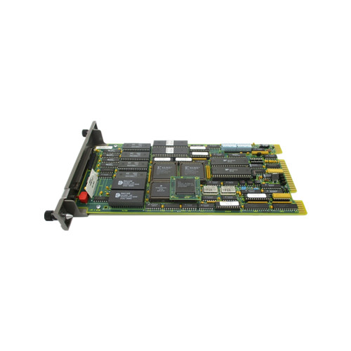
The IMMFP12 Multi-Function Processor Module is a powerful stand-alone controller for use in complex control applications.
It has the processing speeds and storage capabilities necessary for advanced control applications.
The IMMFP12 module is a user-configurable device that receives process input and out put through a variety of analog and digital I/O modules.
This instruction manual provides information about how the IMMFP12 module functions and how to install, configure,operate, and troubleshoot the module.
The IMMFP12 Multi-Function Processor Module (MFP) is one of the workhorses of the INFI 90® OPEN control module line.
It is a multiple loop analog, sequential, batch and advanced controller that provides powerful solutions to process control problems.
It also handles data acquisition and information processing requirements providing true peer-to-peer commu nications.
The comprehensive set of function codes supported by this module handles even the most complex control strategies.
The INFI 90 OPEN system uses a variety of analog and digital I/O modules to communicate with and control the process.
The MFP module communicates with a maximum of 64 modules in any combination (refer to Figure 1-1).
The MFP module has three operating modes: execute, configure and error. In the execute mode, the MFP module executes control algorithms while constantly checking itself for errors. When an error is found, the front panel LEDs display an error code corresponding to the type of error found. In the configure mode,it is possible to edit existing or add new control algorithms. In this mode, the MFP module does not execute control algorithms.
If the MFP module finds an error while in execute mode, it auto matically goes into error mode. Refer to the Section 4 of this instruction for operating mode details.
A one megabaud CPU to CPU communication link allows the MFP module to accommodate redundant processors.
This link enables a backup MFP module to wait in a hot standby mode while the primary MFP module executes the control algorithms.
If the primary MFP module goes off-line for any reason, a bumpless transfer of control to the backup MFP module occurs
CLOCK AND TIMER
The clock section provides the clock signals that drive the module at 16 megahertz.
Additionally, this section supplies the lower order clock signals for the on-board serial links, and the system timer for uniform control algorithm execution.
All clock signals originate from either the 32 megahertz or 7.3728 mega hertz oscillators on the multifunction processor module.
The timer section keeps the multifunction processor module task scheduling at the proper intervals.
One of the UART devices used for serial communication contains the timer section
MEMORY
The MFP module contains 512 kilobytes of ROM memory, 512 kilobytes of random access memory (RAM) and 256 kilobytes of nonvolatile random access memory (NVRAM).
It is important to remember that only 347,712 bytes of RAM memory and 194,752 bytes of NVRAM memory are available for user config urations.
The ROM memory holds the operating system instructions for the microprocessor.
The RAM memory provides temporary storage and a copy of the module configuration.
The NVRAM memory holds the module configuration (control strat egy designed with function codes).
The ability to retain infor mation when power is lost makes this type of memory unique.
Back-up batteries in the NVRAM device that keep the memory active makes this possible.
A key feature of the RAM and ROM memory of the MFP module is that it requires only one wait state.
This means that the microprocessor need only wait one clock cycle before it can check the data in memory.
This results in quicker operation.
I/O EXPANDER BUS
The I/O expander bus resides on the backplane of the module mounting unit.
This bus, an eight bit parallel bus, provides the communication path for I/O data between control and I/O modules.
It supports up to 64 low power I/O modules.
The bus uses a protocol designed by Elsag Bailey to ensure data integ rity.
The bus bandwidth is 500 kilobytes per second, however actual throughput is about 100 kilobytes per second.
I/O SECTION
The input and output section interface allows the microproces sor to read the switches that tell it how to operate and what address it has.
This section contains the latches whose outputs connect to LEDs one through eight and the status LED.
Additionally this section contains an output that desig nates this module as the primary module.
Upon a failover, this output turns off and the backup module output energizes as it takes over. This output actuates an LED that indicates which module is the primary.
Additionally, the input and output section monitors the stop/reset pushbutton.
Pressing the pushbutton once causes this section to bring the module to an orderly stop after completing
any input or output function currently in progress. Pressing the pushbutton a second time resets the module.
SERIAL CHANNELS
The MFP module contains two independent, general purpose serial channels.
One use is for language support (C and BASIC). Each channel supports standard baud rates up to
19.2 kilobaud. The appropriate termination unit or termina tion module uses standard D-type connectors.
The NTMP01,NIMP01, or NIMP02 termination device optically isolates these communication channels.
This optical isolation eliminates the need to tie chassis ground to system common and alleviates the potential of damage from ground currents. One channel can also be used as a RS-485 connection.
DMA SECTION
The microprocessor sets this section for direct memory access or DMA.
The DMA section allows data being received or trans mitted over the various communication paths to be transferred directly to or from the RAM memory without microprocessor intervention.
This process is known as cycle stealing. It greatly reduces the overhead associated with the microprocessor doing
such data moves.
This circuitry is used for the higher speed communication paths where the microprocessor would be overloaded handling the data moves, specifically Controlway.
The 40-kilobaud station link and the redundancy link also use this feature.
Leave a comment
Your email address will not be published. Required fields are marked *