System core configuration
1. Module composition
Basic modules: 6 models (F3BU04-0N to F3BU16-0N), 4-16 slots, supporting different module combinations
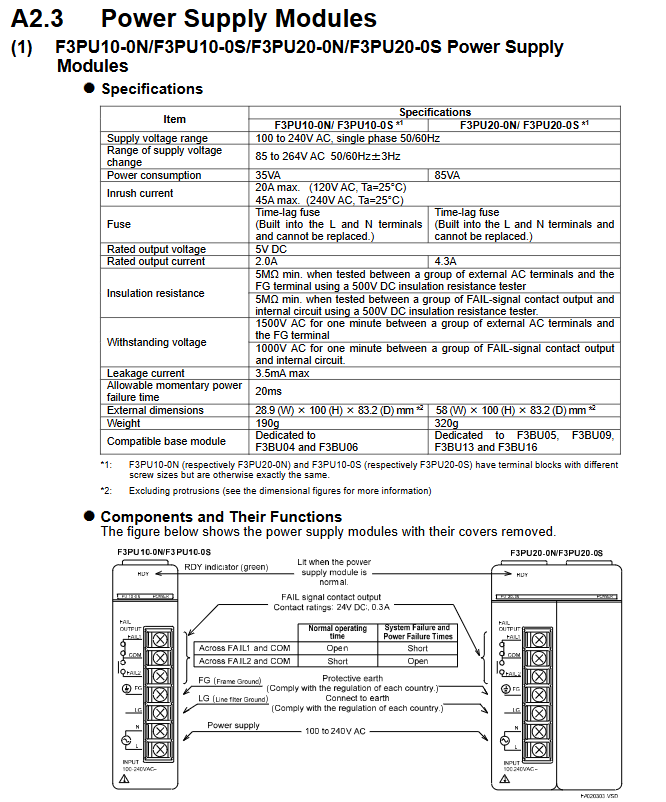
Power module: AC input (F3PU10/20/30 series), DC input (F3PU16/26/36 series), output voltage 5V DC, rated current 2.0A-6.0A
CPU module: including sequential CPU, BASIC CPU, OS free CPU, etc., instruction execution time 0.00375 μ s-0.36 μ s/step, program capacity 5K-254K steps
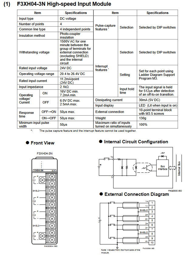
I/O modules: digital (input/output/hybrid), analog (input/output), special modules (temperature control, positioning, communication, etc.), with 8-64 points per module
Expansion modules: Fiber FA bus module, communication module (Ethernet, PROFIBUS-DP, etc.)
2. System topology
Main unit: Must contain 1 CPU module, unit number 0, supports up to 3 extended CPU modules
Slave unit: No CPU module, up to 7, connected to the main unit through a bus, with a maximum of 8192 I/O points per system
Expansion distance: The maximum length of a single section of fiber optic cable is 500m, and the maximum length of a twisted pair cable is 70m
Key technical parameters
1. Environmental and physical parameters
Category specifications
Working temperature 0-55 ℃ (some modules require a narrower range)
Storage temperature -20-75 ℃
Relative humidity 10-90% RH (non condensing)
Installation requirements for indoor use, metal panel enclosure (IK08 and above)
The highest altitude is 2000m
Anti vibration 10-57Hz amplitude 0.075mm, 57-150Hz acceleration 9.8m/s ²
2. Electrical parameters
Power supply fluctuation: AC power supply 85-264V, DC power supply 15.6-31.2V
Insulation resistance: ≥ 5M Ω (tested at 500V DC)
Voltage resistance strength: 1500V AC/1 minute (power terminal – ground)
Leakage current: ≤ 3.5mA (AC power supply)
Allow instantaneous power outage: up to 20ms (standard mode)
3. Performance indicators
CPU processing speed: Basic instructions 0.0175 μ s-0.36 μ s/step (depending on model)
I/O response time: The fastest digital quantity is 50 μ s, and the fastest high-speed module is 0.1ms
Communication speed: Ethernet up to 100Mbps, PROFIBUS-DP up to 12Mbps
Scalability: Supports up to 7 slave units and 32 FA link H module sites
Installation and wiring specifications
1. Installation requirements
Fixing method: DIN rail installation (F3BU04/06/05/09/13) or M4 screw fixation (all models)
Installation gap: Vertical installation spacing ≥ 8cm, unobstructed upper and lower ventilation openings
Module installation: Power off operation, the module needs to be clamped to the locking buckle, and additional screws are required to fix it in the vibration environment
2. Wiring specifications
Conductor requirements: Only copper conductors are allowed, with a cross-sectional area of 0.33-2.1mm ² (AWG14-22)
Terminal torque: M3 screw 0.8N · m, M4 screw 1.2N · m
Anti interference measures:
The distance between signal cable and power cable is ≥ 20cm
Analog signal and digital signal slot wiring
Shielded cable with both ends grounded, bending radius ≥ 50mm (fiber optic)
Grounding requirements:
Protective grounding (FG): connected to the protective grounding grid, cable ≥ 2mm ²
Functional grounding (FG): low impedance grounding, CE compliant requires braided wire
3. CE certification compliance requirements
Electromagnetic compatibility (EMC): EN 61326-1 Class A, EN 55011 Class A
Low Voltage Directive (LVD): EN 61010-1, Overvoltage Category II
RoHS compliance: EN IEC 63000 standard
Testing and Maintenance
1. Testing process
Installation inspection: The module is securely installed and the panel is well ventilated
Wiring inspection: correct polarity, terminal tightening, shielding layer grounding
Insulation test: 500V DC megohmmeter, insulation resistance ≥ 5M Ω
Power on test: If the power indicator light (RDY) is constantly on, it is normal
Functional testing: Safety circuit (emergency stop) → Single module testing → System linkage testing
2. Maintenance points
Regular maintenance: clean panel (soft cloth+neutral cleaner), check cable connections
Spare parts replacement:
Battery: The serial CPU module is equipped with a built-in lithium battery, which has a lifespan of ≥ 10 years at room temperature
Module: Preventive replacement is required after more than 10 years of use
Fuse: 3.15A Delay Fuse (Model A1113EF)
Fault handling: Check the error code through the CPU self diagnostic function. Core errors include module communication failure, power supply abnormality, I/O short circuit, etc
Safety precautions
Power off operation: The power must be turned off before wiring or plugging in modules
Prohibition of modification: It is not allowed to modify the internal circuit or shell of the module
Load limit: The output module must not exceed the rated current (transistor type 0.1A-2A/point, relay type 2A/point)
Environmental protection: Avoid corrosive gases, flammable gases, and radioactive environments
Emergency circuit: An external relay is required to achieve interlocking of the emergency stop circuit
Key questions and answers
Question 1: What is the maximum scalability of the FA-M3 controller? What extension methods are supported?
answer:
Maximum Expansion: The main unit (No. 0) can connect up to 7 slave units (No. 1-7), with a maximum of 8192 I/O points per system (depending on the CPU module model)
Expansion method:
Fiber optic FA bus type 2 module: using fiber optic cables, with a maximum length of 500m per section, strong anti-interference ability
FA bus type 2 module: using shielded twisted pair cables, with a maximum length of 70m per segment, at a lower cost
Local expansion: The basic module supports 4-16 slots, allowing for direct expansion of local I/O modules
Question 2: What are the key requirements for grounding and anti-interference when installing the FA-M3 controller?
answer:
Grounding requirements:
Protective grounding (FG terminal): connected to a protective grounding grid that meets national standards, with a grounding resistance of ≤ 100 Ω and a cable cross-sectional area of ≥ 2mm ²
Functional grounding (FG terminal): To ensure stable operation, grounding is necessary, and CE compliance requires the use of braided wire to ensure high frequency and low impedance
Shielding layer grounding: The two ends of the signal cable shielding layer are grounded and fixed to the metal panel through FG fixtures
Anti interference requirements:
Cable separation: The distance between power cables and signal cables should be ≥ 20cm, and analog and digital signals should be routed in separate slots
Cable selection: Use shielded twisted pair or fiber optic cables to avoid parallel laying with power cables
Filtering measures: The power module is equipped with a built-in noise filter, and sensitive modules can be additionally equipped with ferrite cores
Question 3: What are the types of power modules for the FA-M3 controller? How to choose a suitable power module?
answer:
Power module type:
Type Model Series Input Voltage Rated Output Applicable Basic Module
AC input F3PU10/20/30 100-240V AC 5V DC, 2.0A/4.3A/6.0A F3BU04/06 (10 series); F3BU05/09/13/16 (20/30 series)
DC input F3PU16/26/36 24V DC 5V DC, 2.0A/4.3A/6.0A F3BU04/06 (16 series); F3BU05/09/13/16 (26/36 series)
Selection principle:
Based on the basic module model: 4/6 slot basic module selects 10/16 series, 5/9/13/16 slot selects 20/26/30/36 series
According to power requirements: total current consumption ≤ rated output current of the power supply (all module current consumption needs to be added)
According to the installation environment: CE compliance requires selecting models with the suffix “S” (such as F3PU10-0S)
Based on power supply stability: AC input module is preferred for scenarios with large fluctuations (allowing 85-264V wide range)
Leave a comment
Your email address will not be published. Required fields are marked *