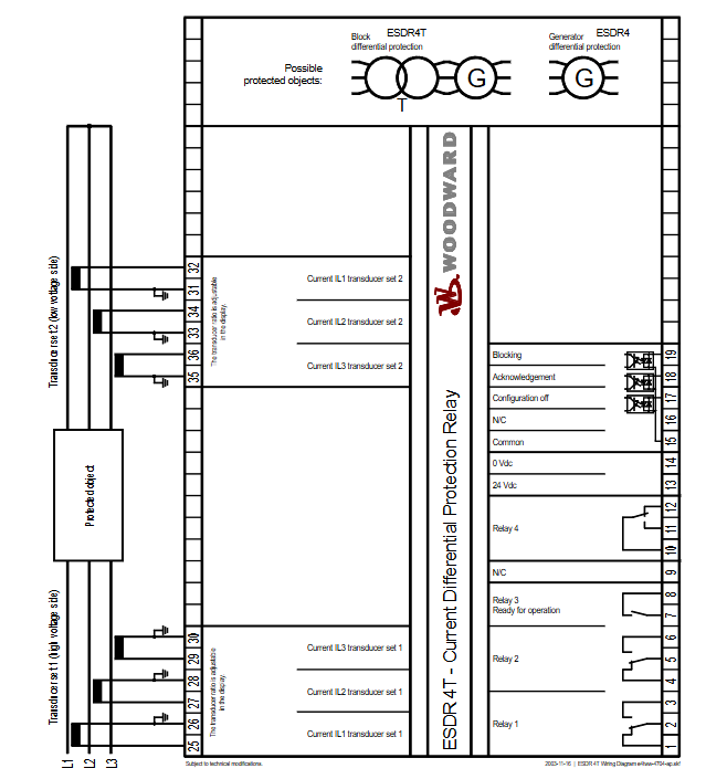
ESDR 4/4T is a series of current differential protection relays launched by Woodward, specifically designed for three-phase current differential protection of generators, motors, and interconnecting transformers. By accurately monitoring the current on both sides of the protection area, identifying fault types, and triggering selective tripping, it ensures the safe and stable operation of power equipment. It is divided into two versions: ESDR 4 (for generators/motors) and ESDR 4T (for generators/motors/interconnecting transformers), and is suitable for harsh power consumption scenarios in industrial, energy, and other fields.
Core Features and Version Differences
1. General core functions
High precision current monitoring: supports 6-channel True RMS current measurement, covering three-phase systems on both sides of the protection area, and can be adapted to the secondary output of current transformers (../1A or…) ./5 A)。
Flexible fault protection: configurable trip thresholds and delays for differential current (Id) and stable current (Is), accurately identifying two-phase/three-phase short circuits and grounding faults; Only when a fault occurs within the protected area, will it trigger a trip, and external faults will not act, achieving selective protection.
Multi interface and alarm: equipped with 4 alarm relays (air contact output) and 3 discrete inputs (for locking, confirmation, and configuration), supporting external PLC remote control; The dual row LC display screen displays real-time operating status and parameters, and supports front-end panel configuration operations.
Reliable hardware design: using microprocessor technology to ensure measurement accuracy, repeatability, and reliability; Compliant with CE certification, UL/cUL certification (for general locations), ESDR 4T additionally has German Lloyd’s (GL) certification, suitable for complex industrial electromagnetic environments.
2. Version difference (ESDR 4 vs ESDR 4T)
Functional dimension ESDR 4 (generator/motor specific) ESDR 4T (including interconnection transformer protection)
The protected objects are only generators, electric motors, generators, electric motors, and interconnecting transformers
Transformer adaptation function is not available. 1. Configurable transformer ratio (independent setting on high and low voltage sides)
2. Transformer vector groups (such as Yd5, Yy0, and 12 other types) can be selected
3. Equipped with transformer excitation inrush current detection and suppression function
Certification standards CE, UL/cUL CE, UL/cUL, GL (German Lloyd’s)
The core advantage is lightweight protection for simple loads, taking into account the complex working conditions of transformers, and adapting to multiple types of power system topologies
Key technical specifications
1. Electrical parameters
Category specification details
Power supply and power consumption: 24 Vdc (± 25% fluctuation); Inherent power consumption: maximum 6 W
Current measurement – isolation design, rated current (I ₙₐₜₑₙ): ./1A or ./5 A
-Current carrying capacity: 5.0 × I ₙₐₜₑₙ; Load:<0.15 VA
-1-second rated short-time current: The./1A version is 100.0 × I ₙₐₜₑₙ, and the./5A version is 30.0 × I ₙₐₜₑₙ
Discrete input isolation design; Input range: 18-250 Vac/dc; Input resistance: approximately 68 k Ω
Relay output – air contact (AgCdO contact material)
-Universal Load (GP): 24 Vdc@2 Adc、250 Vac@2 Aac
-Indicating load (PD): 24 Vdc@1 Adc
2. Environmental and physical parameters
Category specification details
Environmental adaptability – Operating temperature: -20 to 70 ° C (-4 to 158 ° F)
-Storage temperature: -40 to 85 ° C (-40 to 185 ° F)
-Working humidity: 95% (non condensing)
Mechanical Structure – Shell Standard: APRANORM DIN 43700; Protection level: Front IP42, Back IP21
-Size: 144 × 72 × 199 mm (width × height × depth); Front opening: 138 [+1.0] × 68 [+0.7] mm
-Installation method: Front panel installation or DIN rail installation (optional rail clamp P/N LR05188 required)
-Terminal block: screw/plug type, supporting 2.5 mm ² (14AWG) or 4 mm ² (12AWG) wires
-Weight: Approximately 1000 grams
Anti interference and certification – Anti interference testing: compliant with relevant EN standards (CE certification requirements)
-Certification: UL/cUL (ordinary premises), ESDR 4T with additional GL certification included
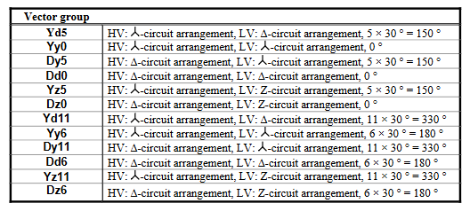
3. Transformer vector group (ESDR 4T exclusive)
Supports 12 common transformer vector group configurations, adapting to different wiring methods by adjusting phase offset. Some core vector groups are as follows:
Vector group wiring method and phase shift
Yd5 high voltage side Y connection, low voltage side Δ connection, offset 5 × 30 °=150 °
Yy0 high voltage side Y connection, low voltage side Y connection, offset by 0 °
Dy11 high voltage side Δ connection, low voltage side Y connection, offset 11 × 30 °=330 °
Dd6 high voltage side Δ connection, low voltage side Δ connection, offset 6 × 30 °=180 °
Ordering Information and Installation
1. Product model (P/N)
Different installation methods and current specifications correspond to different models, and the core models are as follows:
Product Version Installation Method Current Specification Product Number (P/N)
ESDR 4 Front Panel Installation…/1 A LR20459 (ESDR401B)
Front panel installation…/5 A 8441-1010 (ESDR405B)
DIN rail installation…/1 A 8441-1105 (ESDR401M)
DIN rail installation…/5 A LR20590 (ESDR405M)
ESDR 4T Front Panel Installation…/1 A LR20021 (ESDR4T01B)
Front panel installation…/5 A 5448-897 (ESDR4T05B)
DIN rail installation…/1 A LR20616 (ESDR4T01M)
DIN rail installation…/5 A 8441-1047 (ESDR4T05M)
Optional accessories: Front panel version converted to DIN rail mounting rail clamp, P/N LR05188.
2. Installation and wiring
Installation requirements: Must comply with DIN 43700 standard hole size to ensure protection level (front IP42 should avoid direct liquid spray); DIN rail installation requires the use of specialized rail clamps to ensure stable fixation.
Wiring precautions: The current input should be distinguished on both sides of the protection area (such as the high and low voltage sides of the transformer), and the discrete input and relay output should be connected according to the Wiring Diagram to avoid polarity errors that may cause protection misoperation.
Leave a comment
Your email address will not be published. Required fields are marked *