FCS Core Features and Model Classification
1. Core Features
Compact design: The component size is compact, saving control room space and can be installed in IEC Zone2/Class I Div.2 hazardous areas, reducing installation costs
Dual redundancy and high reliability: No single point of failure, processors, power supplies, I/O modules, and communication buses all support redundancy, achieving 99.99999% availability through Pair and Spare technology
Online maintenance: Control applications, logic, and parameters can be modified without downtime to meet factory expansion or renovation needs
Open architecture: Supports third-party Ethernet cables, switches, and other devices, with Vnet/IP bus ensuring communication certainty
Flexible combination of functional blocks: covering multiple types of functional blocks such as regulation, sequence, calculation, etc., supporting flexible design from small to large systems
Multi bus and subsystem integration: supports digital fieldbuses such as FOUNDATION fieldbus and PROFIBUS-DP, and is compatible with communication between devices such as PLC and frequency converter
2. FCS model classification (8 core models)
Model Abbreviation Product Name FCU Model Core Software Package
FFCS-V Vnet/IP and FIO specific FCS AFV30 (rack mounted), AFV40 (cabinet mounted) LFS1700 control function package, LFS1750 node expansion package
FFCS-L Vnet/IP and FIO specific FCS AFV10 (rack mounted) LFS1500 control function package, LFS1550 node expansion package
FFCS FIO Compact FCS AFF50 (Rack mounted) LFS1350 Compact Control Function Package
KFCS FIO standard FCS AFS30 (rack mounted), AFS40 (cabinet mounted) LFS1300 standard control function package
KFCS2 FIO Enhanced FCS AFG30 (rack mounted), AFG40 (cabinet mounted) LFS1330 Enhanced Control Function Package
LFCS RIO standard FCS AFS10 (rack mounted), AFS20 (cabinet mounted) LFS1100 standard control function package
LFCS2 RIO Enhanced FCS AFG10 (rack mounted), AFG20 (cabinet mounted) LFS1130 Enhanced Control Function Package
PFCS/SFCS RIO Standard/Compact FCS PFC – S/E/H (Rack mounted) LFS1000/LFS1020/LFS1120 Control Function Package
Note: represents “S” (single redundancy) or “D” (double redundancy)
Detailed explanation of hardware composition
1. Core components
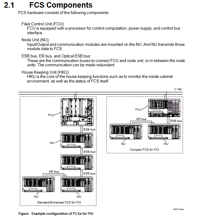
FCU (Field Control Unit): Core computing unit, including processor module, power module, and bus interface module. The dual redundant configuration requires the installation of 2 sets of processors, power supply, and bus interface components
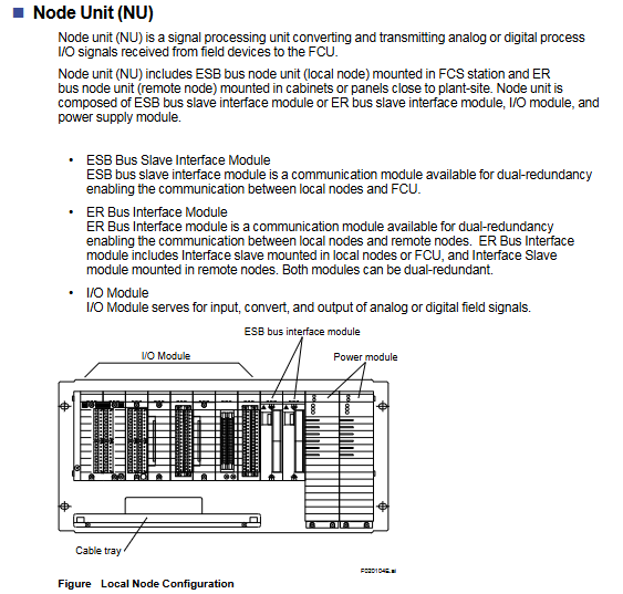
NU (Node Unit): Signal processing unit, including ESB/ER bus interface module, I/O module, power module, divided into local nodes (ESB bus) and remote nodes (ER bus)
Communication bus:
ESB bus: connects FCU with local nodes, supports dual redundancy, and has a maximum transmission distance of 10m
ER bus: connects local and remote nodes, supports dual redundancy, uses Ethernet compatible coaxial cables, and can expand distance through optical relays
Optical ESB bus: only compatible with FFCS-V, supports chain/star topology, with a maximum transmission distance of 50km
HKU (House Keeping Unit): monitors the cabinet environment (temperature, fan status) and FCS’s own status, including HKU main unit, PDU (power distribution unit), fan power supply unit, etc
2. Classification of I/O modules (FIO/RIO specific)
Module type represents model, core specifications
Analog I/O module AAI141 (4-20mA input) 16 channels, non isolated; Supports HART communication version (AAI141-H)
Analog I/O module AAI543 (4-20mA output) 16 channels, isolated; Supports HART communication version (AAI543-H)
Temperature input module AAT141 (TC/mV) 16 channels, isolated; Supports 8 types of thermocouples
Temperature input module AAR181 (RTD) 12 channels, isolated; Suitable for RTD types such as Pt100
Digital I/O module ADV151 (24V DC input) 32 channels, isolated; Support pressure clamp terminals
Digital I/O module ADV551 (24V DC output) 32 channels, isolated; Support dual redundancy configuration
Communication module ALF111 (FF-H1) with 4 ports, supporting FOUNDATION fieldbus
Communication module ALP111 (PROFIBUS-DPV1) 1 port, compatible with PROFIBUS device communication
Turbomachinery module AGS813 (servo module) isolation design, suitable for turbo machinery control
Detailed explanation of control functions
1. Classification of functional blocks (5 major categories of core functional blocks)
Function block type, core function, representative model
Adjusting control block analog process control and monitoring PID-STC (self-tuning PID), ONOFF-G (three bit ON/OFF controller)
Sequence control block interlocking, process monitoring and other sequence logic ST16 (sequence table block), LC64 (logic chart block), TM (timer block)
Calculate block analog quantity/contact signal universal calculation ADD (addition), MUL (multiplication), CalcU (universal calculation)
Panel block multifunctional block unified label display INDST2 (dual pointer indicator station), HAS3C (mixed manual station)
Unit instrument block, whole process unit operation control, UTSW (three position switch type), OPSBL (SEBOL type operation)
2. I/O function
Process I/O: Interacting with field device data, including% Z (process I/O/fieldbus I/O),% WW/% WB (communication I/O)
Software I/O: FCS internal virtual data interaction, including:
Internal switches:% SW (common switch),% GS (global switch)
Message output:% AN (alarm message),% OG (operator guide message),% CP (upper computer event message)
3. Control the drawing and scanning cycle
Control drawing properties:
Visualize the connection between I/O and functional blocks, define execution priorities
Support mixed configuration of regulation control and sequence control
Function blocks that can be connected across different control drawings
Scanning cycle:
Basic scan: fixed for 1 second
Medium speed scanning: 200ms/500ms (default 500ms), some models do not support it
High speed scanning: 200ms/500ms (default 200ms), supports direct input of 50ms/100ms/250ms
Redundancy mechanism (dual redundant core design)
1. Redundant coverage range
Hardware redundancy: processor module, power module, Vnet/IP interface, ESB/ER bus, node interface module
Software redundancy: synchronous computing, data backup, seamless switching logic
2. Core redundancy technology (Pair and Spare)
Processor module: Each module contains 2 MPUs, which synchronously execute the same calculation and compare the results in real-time. If there is inconsistency, a switch will be triggered
Standby module: Real time synchronous active module calculation, ensuring seamless switching and no process interruption
Fault recovery: The fault module automatically self diagnoses, transient errors can be restored to standby state, and hardware faults support online replacement
Bus redundancy: The ESB/ER bus operates alternately in dual channels, automatically switches in case of failure, and undergoes regular testing to restore its state
Subsystem communication (supports 9 types of core communication)
Communication type adaptation equipment core purpose
Data exchange between FA-M3 communication Yokogawa FA-M3/FA500 controllers
Modbus Communication Yokogawa STARDOM, Schneider Modicon Universal Industrial Equipment Communication
MELSEC Communication Mitsubishi MELSEC Series PLC PLC and FCS Data Interaction
PLC-5/SLC 500 Communication Rockwell PLC-5/SLC 500 European and American PLC Integration
YS Communication Yokogawa YS100/YEWSERIES 80 Yokogawa Instrument Direct Connection
FF-H1 Communication FOUNDATION Fieldbus Device Fieldbus Device Integration
Leave a comment
Your email address will not be published. Required fields are marked *