Core objects: Siemens PL series, ES series EQ ® Series and Murray brand load centers, covering 1-phase (120/240V) and 3-phase (240V/120/208V) AC distribution scenarios.
Application scenarios: residential (such as household power distribution), commercial (such as office buildings), industrial (such as factory workshops), and special scenarios (high-rise shafts, generator backup power).
Standard certification:
Standard Number Standard Name Applicable Components
UL 50 Electrical Cabinet and Box Load Center Shell
UL 67 Distribution Panel Integrated Load Center
UL 489 Plastic Case Circuit Breaker Matching QP/QR Series Circuit Breaker
UL 943 Ground Fault Circuit Breaker (Class A) Load Center with GFCI Function (e.g. SPA Panel)
NEC National Electrical Code Installation and Wiring Specification
2. Model coding system (core rules)
Taking PL series P1224B1100CU and ES series S1224B1100 as examples, the coding breakdown is as follows:
Example Explanation of Encoding Segment Meaning (PL Series) Meaning (ES Series)
Initial letter P=PL series (copper busbar) S=ES series (aluminum busbar) P=PL series, S=ES series
Number of vacancies in the first and second digits (1 inch circuit breaker vacancy) Number of vacancies 12=12 vacancies
The number of circuits in the 3rd and 4th digits is 24 circuits
Letter B/L B=main circuit breaker type, L=main terminal block type B=main circuit breaker type, L=main terminal block type B=with main circuit breaker
The 5th to 8th digits represent the rated current (1100=100A, 1200=200A). The rated current is 1100=100A
Model Rated Current Vacancy/Loop Bus Material Shell Size (Height x Width x Depth, inches)
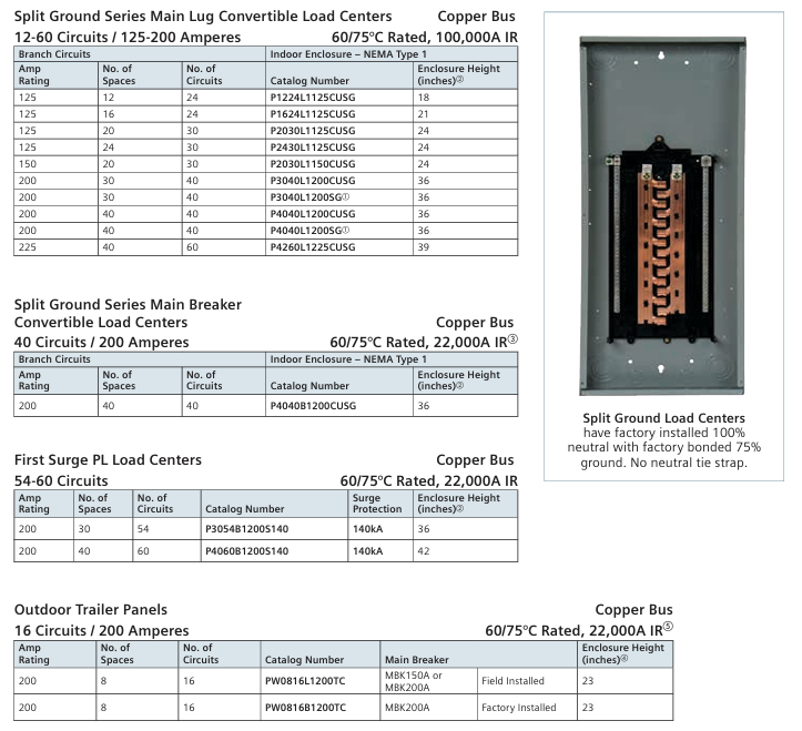
LC2040L1125 125A 20/40 aluminum 24 × 14.38 × 4
LC2040L1125CU 125A 20/40 copper 24 × 14.38 × 4
Installation and accessory selection
1. Key installation specifications
Main circuit breaker conversion: PL series 100A load center requires MBK100A kit, 225A requires MBK225A; The ES series 200A requires MBK200A.
Grounding busbar selection: Match according to the number of circuits, such as EC2GB15 (15 positions) for 24 circuits and EC3GB27 (27 positions) for 40 circuits.
Outdoor installation: NEMA 3R enclosures require HS type hubs (such as ECHS 150 for 1.5 inches and ECHS 200 for 2 inches), and HV type hubs (such as ECHV 200) for high power (>225A).
2. List of core accessories
Accessory type, model description, applicable scenarios, packaging quantity
Main Circuit Breaker Kit MBK100A 1-Phase 100A, 22kA PL/ES Series 100A Load Center 1
Grounding strip EC1GB8 8-position, suitable for small circuit load center 12-24 circuit 1
Locking kit ECQFL2 embedded lock, compatible with PL/ES series to prevent unauthorized operation 1
Fill board ECQF3 1 inch, fill circuit breaker vacancy protection 5
Main terminal block conversion kit ECMLK225 1-Phase 150-225A ES series 200A load center 1
Compatibility and maintenance points
1. Brand compatibility
Murray and PL/ES: Murray load centers can use PL/ES grounding bars (such as ECGB10) and conversion kits (such as MBK150M), but attention should be paid to current matching (such as 125A Murray only compatible with MBK100M/MBK125M).
Circuit breaker compatibility: PL/ES series supports QP/QT/QAF2 series, EQ ® The series supports QR2/QRH2 series and cannot be mixed.
2. Maintenance and safety
Line terminal barrier: The main circuit breaker type load center produced after 2017 comes standard with barriers (such as ECLTB1 compatible with 100-125A, ECLTB2 compatible with 150-225A) to prevent accidental contact.
Regular inspection: The grounding bar connection torque must meet the requirements (such as 45 lb ins for 2/0 wires and 340 lb ins for 300kcmil wires), and the neutral wire must not be loose.
Suggestions for scenario based selection
Recommended Scene Types, Series Model Examples, Key Considerations
Residential (100A, 24 circuits) ES series S1224B1100 has low cost and aluminum busbar meets general needs
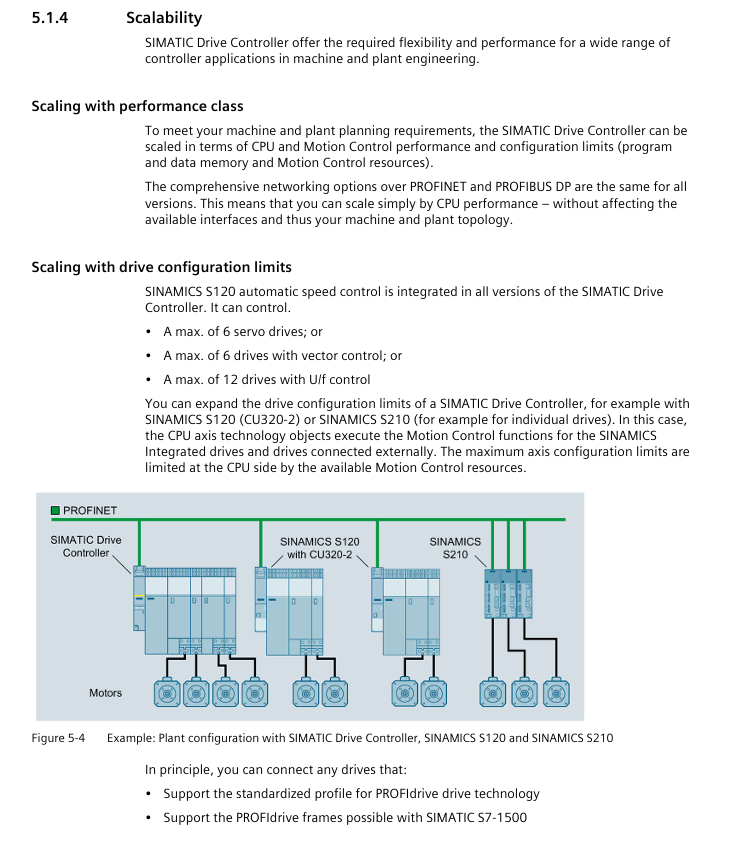
Scope: Covering the entire range of SIMATIC Drive Controllers, including CPU 1504D TF/1507D TF and SINAMICS Integrated, providing full process guidance from planning to maintenance, suitable for Motion Control scenarios such as multi axis machine tools, packaging machinery, printing equipment, etc.
Security level classification:
Warning type risk description example scenario
DANGER Fatal/Serious Personal Injury Contact with Live Parts, Undischarged Capacitors
Warning: May cause fatal/serious injury. Equipment damage may lead to electrical leakage, and wireless devices may interfere with safety functions
CAUTION Minor personal injury, electrostatic discharge damage to components
NOTICE property loss, wiring error leading to module failure
Qualification requirements: Only personnel with “industrial automation qualification” are allowed to operate, and they must be familiar with standards such as IEC 61131-2 and EN 60204.
2. Industrial network security (new core chapter added)
Protection strategy: Adopting the “Defense in Depth” framework, divided into 3 layers of protection:
Physical security: Lock the control cabinet door and manage access permissions (password/fingerprint)
System integrity: firmware updates, configuration verification, data backup
Key measures:
Regular firmware updates (via TIA Portal/memory card/web server)
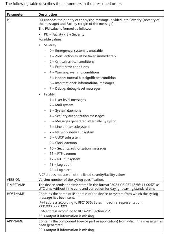
Syslog log: CPU local cache security events (such as password errors, configuration tampering) can be forwarded to the server (UDP port 514/TLS port 6514)
Data destruction: Before retiring the device, a “factory reset” (SINAMICS first, CPU later) must be performed to format the storage card or physically destroy it
System Overview and Core Components
1. Comparison of Core Parameters of Controllers
Component model: CPU 1504D TF (for small and medium-sized applications) CPU 1507D TF (for high-end applications) Key differences
Code working memory 4 MB 15 MB 1507D supports more complex programs
Data working memory 6 MB 40 MB 1507D can store more real-time data
Number of positioning axes (maximum) 40 160 1507D Supports multi axis synchronization
Motion Control resources 3200 12800 1507D handle higher loads
Minimum cycle 500 μ s 250 μ s 1507D supports higher real-time performance
Restrictions: Free Function Blocks (FBLOCKS) and SIMOTION CX32-2 extensions are not supported, only partial technical extensions (such as POLYGON/SETPGEN) are supported
Application planning and installation wiring
1. Hardware configuration rules
Power configuration:
System power supply: 24V DC PELV (such as SITOP smart), no-load current 1.7A, maximum load 13.1A
Drive power supply: SINAMICS Line Module (generates DC link voltage), Motor Module takes power from the DC link
The official system manual for Siemens SIMATIC S7-1500 automation system and ET 200MP distributed I/O system was released in December 2014 (document number A5E03461182-AC), aiming to provide technical guidance for industrial automation engineers throughout the entire process from project planning to equipment maintenance, suitable for scenarios such as machine manufacturing and process control. The document follows a “general sub general” structure, first outlining the system positioning and components, then explaining the implementation details in modules, and finally supplementing technical parameters and appendices to ensure the coherence and operability of information.
System Overview and Core Components
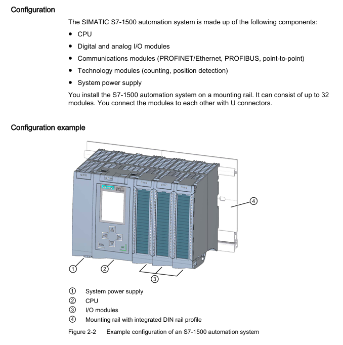
1. S7-1500 automation system
Positioning and advantages: As an upgraded product of S7-300/400, it focuses on high cost-effectiveness and compact design, supports up to 32 modules (slots 0-31), integrates high-speed backplane bus (improves data transmission efficiency), web server (remote monitoring) and Motion Control function (drive control), meets IP20 protection level, and needs to be installed in the control cabinet.
Core components:
Example of Key Parameters for Component Type Function Description
The CPU executes user programs and provides PROFINET/PROFIBUS communication interface model 1518-4PN/DP, supporting 8 communication modules
The system power supply (PS) is powered by the backplane bus, and the diagnostic function integrates PS 25W 24V DC and PS 60W 120/230V AC/DC
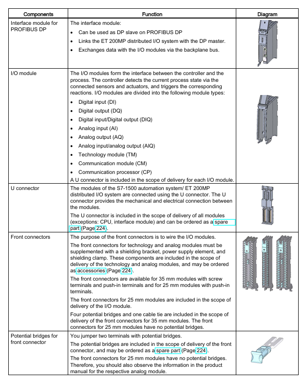
I/O module for digital/analog signal acquisition and output, including technical modules (counting, positioning), digital module DI 32x24VDC HF, analog module AI 8xU/I
Communication module (CM) extends communication interface, supporting point-to-point (RS232/RS485), PROFINET/Ethernet CM 1542-5 (DP master/slave)
2. ET 200MP distributed I/O system
Positioning and advantages: A scalable distributed I/O solution that communicates with the central controller through PROFINET/PROFIBUS, supports high channel density (25mm wide module with 32 channels), adapts to S7-1500 I/O modules, and can be flexibly expanded to 30 I/O modules (PN interface) or 12 I/O modules (DP interface).
Core components:
Example of Key Parameters for Component Type Function Description
The interface module (IM) connects distributed I/O with the central controller, and supports isochronous mode (250 μ s cycle) for PROFINET version (IM 155-5 PN ST/HF) or PROFIBUS version (IM 155-5 DP ST) IM 155-5 PN HF
The I/O module is compatible with S7-1500 and supports digital, analog, and technical modules with the same parameters as S7-1500 I/O module
The system power supply (PS) is powered by the backplane bus and needs to be separately configured with the same S7-1500 system power supply
Application planning and hardware configuration
1. Hardware configuration rules
S7-1500 configuration restrictions:
Module type allows maximum number of slots. Please note
Load power (PM) slot 0 has no limit (only 1 is displayed in STEP 7) and does not occupy the backplane bus. External wiring is required
System power (PS) slots 0, 2-31, 3 for supplementing backplane bus power
CPU slot 1: 1 required component, indispensable
I/O modules 2-31, 30 including digital, analog, and technical modules
Communication module 2-31 4-8 (depending on CPU model) CPU 1511-1PN supports 4, 1518-4PN/DP supports 8
ET 200MP configuration limit:
Interface type allows maximum number of I/O modules in the slot. Remarks
PROFINET (IM 155-5 PN) slot 1 30 (slots 2-31) supports system power expansion (up to 3)
PROFIBUS (IM 155-5 DP) slots 2 12 (slots 3-14) without system power expansion function
2. Power configuration and power balance
Classification of power supply types:
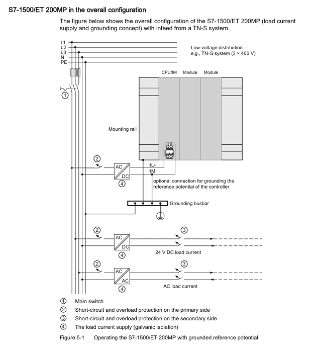
System power supply (PS): only supplies power to the backplane bus (module electronic components, LEDs), needs to be connected to the backplane through a U connector, supports 24/48/60V DC or 120/230V AC input;
Load Power Supply (PM): Provides power to I/O module input/output circuits, sensors/actuators, without backplane bus connection, installed on rails but not occupying slots, recommended Siemens SIMATIC series (PM 70W/190W 120/230V AC).
Power balance calculation: It is necessary to ensure that the backplane bus “supply power ≥ consumption power”, and STEP 7 will automatically verify. If the power is insufficient, the system power supply needs to be added. The calculation logic is as follows:
Calculate the backplane power supply of CPU/interface modules (such as 14W provided by CPU 1516-3 PN/DP);
Accumulate the power consumption of each I/O module (such as DI 32x24VDC HF consumption of 1.1W);
If the total consumption exceeds the supply, a system power supply (such as PS 25W to supplement 25W) needs to be added to slot 2-31.
Installation and wiring specifications
1. Installation process and requirements
Guide rail installation: Use TH 35 standard guide rails (length 160/245/482.6/530/830/2000mm), with M6 fixing screws (torque 4Nm). For guide rails ≥ 530mm, fixing screws should be added every 500mm;
Module installation sequence: From left to right, it is “System power supply (optional) → CPU/interface module → I/O module”. The modules are mechanically and electrically connected through U connectors, and the last module does not require the installation of U connectors;
Minimum gap: A gap of ≥ 25mm (for heat dissipation and operation space) should be left at the top/bottom of the module. The operating temperature for horizontal installation is 0-60 ℃, and for vertical installation it is 0-40 ℃.
2. Wiring rules
Power wiring:
CPU/Interface Module: Connected to 24V DC (L+, M) through a 4-pole plug, with wire cross-sections of 0.25-2.5mm ² (multiple strands without conduit) and 0.25-1.5mm ² (multiple strands with conduit), and a stripping length of 10-11mm;
System power supply/load power supply: Connected through an encoded power plug, AC input needs to distinguish L1/N, DC input needs to distinguish L+/M, wire stripping length is 7-8mm, torque is 0.5-0.6Nm.
Spring type terminal (push in) 35mm/25mm, tool free hard wire directly inserted, multi strand wire needs to be stripped 8-11mm
The simulation module requires additional installation of shielding brackets and shielding clamps to ensure EMC protection (interference current is grounded through the rail).
Configuration and Debugging Process
1. Software Configuration (STEP 7 TIA Portal)
Basic configuration steps:
Create a project and add S7-1500/ET 200MP devices;
Hardware detection: After connecting to the CPU online, the actual configuration is automatically read through “Hardware detection” to avoid manual input errors;
Address allocation: STEP 7 automatically assigns I/O addresses (digital modules by bit/byte, analog modules by word), supports manual adjustment, can be divided into 32 process image partitions (PIP), PIP 0 is automatically updated, PIP 1-31 can be bound to OB blocks;
Download configuration: The CPU needs to be in STOP mode, and check “Consistent download” to ensure data integrity.
Key configuration functions:
Configuration control: “one main configuration adapts to multiple sub configurations” is realized through control data record (No. 196), which supports module slot adjustment or omission. It is necessary to call WRREC command to transmit data in startup OB;
Block protection: Set know-how protection (password encryption, only displaying interfaces and comments) and copy protection (binding CPU/SIMATIC storage card serial number) for OB/FC/FB/DB.
After power on, the CPU performs a self-test (LED flashes all → STOP light turns yellow). If there is a fault, check the diagnostic buffer.
IO testing:
Scan the PROFINET network and test I/O wiring using the PRONETA tool (free of charge);
Monitor/modify variables through STEP 7 “Watch&Force Tables”, or directly operate on the CPU display screen (supporting forced peripheral input/output).
Program processing and security protection
1. Fundamentals of Program Processing
Organizational Block (OB): Execute based on event triggers, priority 1-26 (1 lowest, 26 highest), core OB functions are as follows:
OB Number Triggering Event Priority (Default) Function Description
OB 1 loop program 1 main loop executes user program
OB 10-17 timed interrupt 2 triggered at the set time (e.g. every 100ms)
OB 40-47 hardware interrupt 18 triggered by I/O module signal (such as rising edge)
OB 80 time error 22 triggered when cycle time exceeds the limit
OB 121 programming error 7 triggered when there is a syntax error in the program
CPU overload handling: The event queue caches events of the same priority. If the “maximum number of queues” is exceeded, they will be discarded. The time error OB can be triggered through the “event threshold” (such as calling OB 80 when the number of queues is ≥ 1).
2. Safety protection
Access protection: Level 4 permission control, password needs to be configured in CPU properties:
Protection level permission description
Full access to read and write hardware configuration and blocks, no password requirement
Read only access Read only configuration/block, cannot be downloaded, requires password to unlock write permission
HMI access is only available for HMI and diagnostic access, and requires password unlocking for read and write permissions
No access, all access is prohibited. Password unlocking is required
Other protections:
Physical protection: The front cover of the CPU/interface module can be locked (with a diameter of 3mm) or sealed with a seal;
Network protection: Disable unused communication interfaces (such as NTP, PUT/GET), and only allow HTTPS access to the web server.
Maintenance and fault diagnosis
1. Daily maintenance
Module replacement: When replacing the I/O module after power failure, attention should be paid to the coding components (the front connector should be separated from the module when first inserted to ensure that it is only compatible with modules of the same type);
Firmware update: supports 3 methods (online STEP 7, SIMATIC memory card, web server), requires CPU in STOP mode, 2GB card can update CPU 1517/1518 firmware;
Factory reset: By using the mode selector (MRES key), display screen, or executing STEP 7, the IP address and user program will be cleared, leaving only the MAC address.
2. Fault diagnosis
Diagnostic buffer: records CPU/module faults (such as power overload, configuration mismatch), which can be read through STEP 7 or CPU display screen;
Service data reading: In the event of a malfunction, export the DUMP.S7S file through a web server, STEP 7, or SIMATIC storage card for analysis by Siemens technical support;
Testing function:
LED flash test: After triggering, the CPU RUN/STOP/ErrOR/MAINT lights flash to locate the device;
Trace function: records variable changes (such as drive parameters), supports triggering condition settings (such as value exceeding threshold).
Technical Parameters and Appendices
1. Core technical parameters
Environmental parameters:
Parameter Type Range Remarks
Operating temperature 0-60 ℃ (horizontal)/0-40 ℃ (vertical) Display screen automatically shuts down due to overheating
Storage temperature -40-80 ℃ under original packaging conditions
Relative humidity of 10% -95% (no condensation) in accordance with IEC 61131-2 3K3 level
Vibration/shock 5-9Hz (3.5mm amplitude)/250m/s ² (6ms) in accordance with IEC 60068-2-6/27
Contactor relay is a key component for achieving “signal amplification and circuit switching” in industrial control. The document focuses on the 3RH2 and 3TH4 series, which complement each other in positioning and adapt to different scene requirements.
3RH2 series (size S00, compact)
(1) Product positioning and core features
Specially designed for compact control cabinets, with a size of only S00 (45mm wide), supporting 4-pole, 8-pole, and 4-pole latch types, it is the “basic contactor relay” of Siemens SIRIUS series, with core advantages including:
Multiple terminal selection: screw terminals (traditional wiring) and spring terminals (push in, tool free quick wiring) are optional;
Climate adaptation: operating temperature -25~+60 ℃, storage temperature -55~+80 ℃, suitable for use in high/low temperature industrial environments (such as cold chain workshops and metallurgical plants);
Safety compliance: Compliant with the IEC 60529 finger protection standard, both the basic unit and auxiliary switch have “forced guide contacts” (Appendix L of IEC 60947-5-1), which can be used for safety related applications (such as emergency stop circuits).
(2) Detailed product classification and model analysis
According to their functions and application scenarios, the 3RH2 series can be divided into four categories, with model codes following a fixed logic (“3RH2 @ @ – @ @ @ @ 0- @ @ @ @”). The meanings and examples of each field are as follows:
Product type Pole number Terminal type Coil voltage Model example Key characteristics Corresponding page numbers
Standard contactor relay 4-pole screw terminal 24V AC (50/60Hz) 3RH2140-1AB00 basic model, 4NO contact, terminal identification in accordance with EN 50011 5/12, 5/13
Standard contactor relay 8-pole spring terminal 230V AC (50/60Hz) 3RH2244-2AP00 8-pole (4NO+4NC) with permanently installed auxiliary switches 5/12, 5/13
Lock type contactor relay 4-pole screw terminal 24V DC 3RH2440-1BB40 requires external signal unlocking, suitable for “hold type circuit” (such as gate control) 5/12, 5/13
Coupling contactor relay (PLC compatible) 4-pole screw terminal 24V DC 3RH2140-1HB40 low power consumption (2.8W), wide coil working range (0.7~1.25 × Us), compatible with PLC solid-state output 5/14, 5/15
Railway application type contactor relay 4-pole screw terminal wide voltage coil 3RH2122-2K.40 coil voltage range extension, anti vibration (AC operation 11.4g/5ms) 4/64
(3) Key technical parameters (detailed explanation by dimension)
Technical parameters are the core basis for selection, and the document specifies the electrical, mechanical, and environmental performance of the 3RH2 series through tables and charts. The core data is as follows:
Size and Installation:
Component type Terminal type Width x Height x Depth (mm) Installation method
Basic unit screw terminal 45 × 58 × 73 fixed with screws/TH 35 rail clamp
Basic unit spring terminal 45 × 70 × 73 fixed with screws/TH 35 rail clamp
Insulation voltage (Ui, pollution level 3): 690V, suitable for medium and high voltage industrial circuits;
Surge withstand voltage (Uimp): 6kV, strong resistance to grid surges;
Coil power consumption (cold state, 1.0 × Us):
AC 50Hz: Close at 37VA/power factor 0.8, maintain at 5.7VA/power factor 0.25;
AC 60Hz: closed 33VA/power factor 0.75, maintained 4.4VA/power factor 0.25;
DC: closed=hold, 4.0W (low power consumption suitable for battery powered scenarios);
Contact reliability: Contact stability at 17V/1mA (IEC 60947-5-4), fault frequency<10 ⁻⁸ (<1 fault per 100 million operations).
Lifespan and Durability:
Component type Mechanical life (10000 cycles) Electrical life (AC-15/230V, 10000 cycles) Remarks
Basic unit 3000 100 without auxiliary accessories, randomly switched (asynchronous phase)
Basic unit+auxiliary switch 1000 50 Auxiliary switch is front mounted, 4-pole maximum expansion
Solid state compatible auxiliary switch 500 30 compatible with solid-state circuits, without forced guiding contacts
(4) Accessory System and Application Expansion
The 3RH2 series supports a variety of accessories, which can achieve functional upgrades and convenient maintenance. The core accessories are as follows:
Accessory type, model, example, function description, installation method, corresponding page number
Functional modules 3RA281., 3RA283. Direct start, star delta start module, integrated control logic front mounted 3/107
Surge suppressor 3RT2916-4MA10 RC component/varistor/diode, suppression coil disconnect surge front mounted, with LED indication 3/104, 3/105
Additional load module 3RT2916 increases allowable residual current (compatible with high residual current PLC output) Front mounted 3/121
Anti misoperation cover plate 3RT2916-4MA10 sealed terminal, preventing accidental contact or tampering with snap on cover 3/119
(5) Selection and ordering precautions
Model coding logic: It is necessary to clarify “number of poles → contact type (NO/NC) → terminal type → coil voltage → special version”, for example, in “3RH2122-1AB00”, “22” represents 2NO+2NC, “1” represents screw terminal, and “AB00” represents 24V AC coil;
Minimum order unit (PU): 1 unit (single unit), discounts are available for partial bulk orders (please consult Siemens sales);
Special requirements: Railway application type (wide voltage coil) and latch type require separate confirmation of delivery time, non-standard voltage (such as 48V DC) can be customized according to the “3/75 page” requirements.
2. 3TH4 series (8-pole/10 pole, multi circuit type)
(1) Product positioning and core differences
Unlike the “compact” positioning of the 3RH2 series, the 3TH4 series focuses on multi pole numbers and high reliability, designed specifically for “multi loop centralized control” scenarios (such as complex motor control and machine tool hydraulic systems). The core differences are reflected in:
More poles: Only 8 poles (3TH42) and 10 poles (3TH43), supporting more independent circuit switching;
More stable structure: greater depth (AC type 97mm, DC type 130mm), stronger impact resistance (AC operation 12g/5ms);
Single terminal type: only screw terminals (M3.5), suitable for connecting large cross-sectional wires (up to 4mm ²);
Narrow environmental adaptability: operating temperature -25~+55 ℃ (5 ℃ lower than 3RH2), more suitable for industrial environments at room temperature.
(2) Product classification and key parameters
Product classification: Divided by pole number into 3TH42 (8 poles) and 3TH43 (10 poles), both support AC/DC coils. The model examples are as follows:
Series pole control voltage terminal type model example corresponding page number
3TH42 8-pole 230V AC (50Hz) screw terminal 3TH4280-0AP0 5/20
3TH42 8-pole 24V DC screw terminal 3TH4280-0BB4 5/20
3TH43 10 pole 230V AC (50Hz) screw terminal 3TH4310-0AP0 5/21
3TH43 10 pole 24V DC screw terminal 3TH4310-0BB4 5/21
Core technical parameters:
Insulation voltage (Ui): 690V, impulse withstand voltage (Uimp): 8kV (2kV higher than 3RH2);
Contact current capacity (AC-15): 10A at 230V, 6A at 400V, 4A at 500V, 2A at 690V;
Mechanical lifespan: 30 million cycles (basic unit), electrical lifespan (AC-15/230V): 3.6 million cycles (3 times higher than 3RH2).
(3) Accessories and Special Features
Surge Suppressor: 3TX7402 series, including diodes (24~250V DC, 3TX7402-3A), varistors (24~600V AC, 3TX7402-3G), RC components (24~600V AC, 3TX7402-3R), directly installed on coil terminals to suppress disconnection surges;
Delay device: 3TX4180-0A (ON delay, 0.1~5s), suitable for circuits that require delayed start (such as fan soft start);
Railway application type: coil voltage range extension (0.85~1.1 × Us), model such as 3TH42. -0B., needs to be ordered according to the requirements on page 4/66.
Coupling relay
Coupling relays mainly achieve electrical isolation and signal level matching between control circuits and load circuits. The document covers three major series: 3RQ2, 3RQ3, and LZS/LZX, corresponding to “industrial shell type, narrow design type, and plug-in customized type”, meeting different installation spaces and customization requirements.
3RQ2 series (industrial shell type, 22.5mm)
(1) Product positioning and core advantages
Replacing the traditional 3RS18 series, designed specifically for industrial grade signal coupling, with a 22.5mm wide industrial casing (titanium gray) that is visually consistent with the SIRIUS series. The core advantages include:
Wide voltage compatibility: 24~240V AC/DC coils, no need to distinguish between AC and DC, reducing inventory types;
High contact reliability: Some models use “hard gold-plated contacts” (AgNi+Au), which provide stable contact in low current (≥ 1mA) and low voltage (≥ 17V) scenarios;
Easy to maintain design: detachable terminals (screw/spring type), no need to disconnect wires to replace terminals; TOP wiring (front wire entry) increases wiring efficiency by 30%.
(2) Product Classification and Technical Parameters
Product classification: Divided by the number of contacts into 1 conversion (CO), 2 conversion, and 3 conversion. Model examples and parameters are as follows:
Number of contacts, terminal type, contact material, coil voltage range, model example, working temperature, insulation voltage, corresponding page number
Mechanical lifespan: 10 million cycles, electrical lifespan (AC-15/230V): 100000 cycles;
Protection level: IP20 (front), preventing solid foreign objects from entering.
(3) Accessories and Selection
Core accessories:
Accessory type, model, example, function description, ordering unit, corresponding page number
Detachable terminal 3ZY1122-1BA00 2-pole, screw terminal, maximum 4mm ² wire 6 units 5/26
Hinge cover 3ZY1450-1AB00 titanium gray, no terminal identification, protective terminal 5 units 5/26
Code pin 3ZY1440-1AA00 mechanical code terminal to prevent accidental insertion of 12 units 5/26
Special screwdriver 3RA2908-1A 3.0 × 0.5mm, designed for dismantling spring type terminals with 1 unit 5/26
Selection precautions: It is necessary to clarify the “number of contacts → terminal type → contact material → coil voltage”, for example, “3RQ2000-2CW01” represents “2 conversion contacts, spring terminals, hard gold-plated contacts, 24-240V AC/DC coils”.
3RQ3 series (narrow design type, 6.2mm)
(1) Product positioning and core innovation
Specially designed for high-density control cabinets, with a width of only 6.2mm (1/4 of traditional coupling relays), it is a representative of Siemens’ “miniaturized coupling relays”, with core innovations including:
TOP wiring+spring type terminal: front wire entry, tool free wiring, suitable for batch installation (such as automated production line control cabinets);
Multiple output types: Relay output (non plug/unplug) and semiconductor output are optional, suitable for different switching frequency requirements;
Integrated protection function: reverse polarity protection, EMC arc suppression diode, reducing the use of external protection components.
(2) Product Classification and Technical Parameters
Product classification: Divided into 3 categories based on output type, the core differences and parameters are as follows:
Output Type Model Series Contact/Output Characteristics Coil Voltage Range Operating Temperature Insulation Voltage Corresponding Page Number
Semiconductor output (non plug and play) 3RQ3050/3RQ3070 contactless, 1mA~5A current capacity 11~30V DC/110~230V AC/DC -25~+60 ℃ 300V 5/34
Key performance differences:
Relay output: with a mechanical lifespan of 10 million cycles, suitable for switching between medium and low frequencies (≤ 1000 cycles/hour);
Semiconductor output: No mechanical wear, suitable for high-frequency switching (≤ 10000 times/hour), no contact bounce and noise.
(3) Accessories and Application Scenarios
Core accessories:
Accessory type, model, example, function description, ordering unit, corresponding page number
Isolation board 3RQ3900-0A electrically isolates different voltage circuits to prevent crosstalk of 10 units 5/35
Connect comb 3RQ3901-0A (2-pole) to the same potential terminal, with a current capacity of 6A 10 units 5/35
Label 3RQ3902-0A (5 × 5mm) Terminal Identification, White Handwritten 2000 units 5/35
Replace relay module 3TX7014-7BM00 with 3RQ3118, AgSnO2 contacts 15 units 5/35
Typical application scenarios:
Relay output: signal coupling between PLC and contactor (such as motor start stop control);
Semiconductor output: sensor signal amplification (such as photoelectric switch → PLC input), high-frequency light control.
3. LZS/LZX series (plug-in customized type)
(1) Product positioning and core features
Specially designed for customized control requirements, supporting free combination of “relay module+base+accessories”, with core features including:
Multi type coverage: PT (industrial type, 28mm wide), MT (circular base, 38mm wide), RT (printed type, 15.5mm wide), suitable for different installation scenarios;
High environmental adaptability: Operating temperature -40~+70 ℃, can be used in extreme environments (such as outdoor control cabinets, high-temperature ovens);
Easy to maintain: Plug in relays can be replaced without disconnecting wires, reducing maintenance time by 80%.
(2) Product Classification and Technical Parameters
Product classification: Divided into 3 categories by structure, with the following core parameters:
Type Width (mm) Contact Quantity Terminal Type Coil Voltage Range Operating Temperature Insulation Voltage Corresponding Page Number
Customized assembly logic: Users can select in the order of “relay module → base → LED module → protective component”, as shown in the following example:
Accessory type, model, example, function description, adaptation type, corresponding page number
LED module (red) LZS: PTML0024 24V DC, with freewheeling diode, indicating relay status PT type 5/42
Fixed/pop-up bracket LZS: PT17021 auxiliary disassembly relay, suitable for dense installation of PT type 5/42
RC component LZS: PTMU0524 suppresses coil surge, 24~60V AC PT/MT/RT type 5/42
Connect comb LZS: PT170R6 (6-pole) to the same potential terminal, current capacity 10A PT type 5/42
General Technical Specifications and Safety Standards
At the end of the document, the universal connection methods, security features, and standard certifications for the entire series of products were added to ensure the compliance and security of technical applications.
1. Connection method (universal across the entire series)
Screw terminal: requires tool fastening, wire section 0.5~4mm ² (solid/multi strand with end sleeve), torque 0.8~1.2Nm (3RH2), 0.6~0.8Nm (3RQ2), suitable for large section wires and low vibration scenarios;
Spring terminal (push in):
Advantages: Tool free wiring (hard wire/soft wire with end sleeve), requires a 3.0 × 0.5mm screwdriver for wire removal, earthquake resistant (no risk of loosening), and does not require regular torque checks;
Plug in terminal: Only supported by LZS series, suitable for scenarios that require frequent replacement of relays, with a wire cross-section of 0.75~1.5mm ².
2. Safety features and standard certification
Core standards:
IEC/EN 60947-1: General Standard for Low Voltage Switchgear;
IEC/EN 60947-4-1: Standard for contactors and motor starters;
IEC/EN 60947-5-1: Electrical standard for control circuits (including requirements for mandatory guide contacts);
IEC 60529: Standard for Degrees of Protection Provided by Enclosures (IP20/IP00/IP50).
Security features:
Finger protection: The front meets IP20 standards to prevent fingers from coming into contact with live parts;
Mandatory guiding contact: 3RH2 and 3TH4 series basic units are equipped to ensure that NO/NC contacts do not close simultaneously (essential for safe applications);
Short circuit protection: Suitable for G-type fuses (such as 3NA, 5SB) or C/B characteristic miniature circuit breakers, with a short-circuit current of 1kA (IEC 60947-5-1).
3. General requirements for installation and maintenance
Installation position: Vertical installation (base facing up), when installing 3TH4 series AC type on the side, a 5mm gap should be left (to prevent overheating);
Wiring specification: Separate the wiring of coils and contact circuits to avoid electromagnetic interference;
Maintenance cycle: Check the terminal fastening status (screw terminals) and contact wear every 6 months (measured by LED indicator or multimeter).
Summary and Core Values
This document serves as the authoritative technical manual for Siemens SIRIUS series switchgear, with core values reflected in:
Technical integrity: covering the entire series of contactor relays and coupling relays, with detailed parameters (including size, current, and lifespan), clear selection logic, and can directly guide engineering design;
Targeted application: classified according to “compact → multipole → industrial → narrow design → customized”, suitable for different installation spaces and scene requirements;
Safety compliance: Clarify standard certification and safety features to help users avoid electrical safety risks;
Maintenance convenience: Detailed list of accessory system and maintenance specifications to reduce later operation and maintenance costs.
(1) Basic rules for parameters (supplementary configuration logic)
Parameter number and type
Number format: Read and write parameters starting with “p” (such as p0003), read-only parameters starting with “r” (such as r0002, displaying the running status of the driver);
Index identifier: with [0… n] indicating multiple index parameters (such as p0304 [0… n], supporting storage of multiple motor parameters);
Bit field identifier: with. 0… n represents bit parameters (such as r0046.0, corresponding to the switch status of specific functions).
Parameter access and modification rules
Access level control: Set through P0003, Level 3 (expert level) includes 1-2 levels of functionality, and Level 4 (service level) requires a password (p3950) to unlock;
Modification effective conditions: Some parameter annotations “C (x)” indicate that they can only be modified in debugging mode (p0010=x), “U” indicates that they can be modified during operation, “T” indicates that they can be modified in the ready state, and some parameter modifications require restarting the frequency converter to take effect;
The impact of associated parameters: The “Linked parameterization” feature automatically synchronizes the modification of associated parameters when modifying some parameters (such as p0922 PROFIBUS telegram), and the impact range needs to be confirmed in advance.
(2) Detailed analysis of core parameter module
1. Basic configuration parameters (p0000-p0999)
Parameter Number Parameter Name Core Function Value Range Default Values Key Explanation
The parameter range that can be viewed/modified in the access level control of P0003 is 3 (expert), 4 (service), and 3/4. The password p3950 is required for level 4, and only authorized service personnel can operate it
P0015 Driver Unit Macro Run Preset Macro File, Quickly Configure Typical Application Scenarios 0-999999 7 (CU240B-2)/12 (CU240E-2) After Execution, Parameter Lock, R3996=0 is Required to Modify Again
P0096 Application class switching control view (adapted to different application scenarios) 0=Expert, 1=Standard drive control, 2=Dynamic drive control 0 1=Suitable for standard loads such as pumps/fans, 2=Suitable for high dynamic response loads (such as machine tools)
P0100 Standard Selection (IEC/NEMA) Switching Motor Parameter Unit System 0=IEC, 1=NEMA, 2=NEMA+SI 0 0=Power Unit kW, Frequency 50Hz; 1=Power Unit hp, Frequency 60Hz
P0170 Command Dataset Quantity (CDS) Configuration: The number of storable command datasets is 2-4. 2 Supports quick switching of different control commands (such as manual/automatic frequency source switching)
P0180 Driver Dataset Quantity (DDS) Configuration: The number of storable driver datasets ranges from 1 to 4, and supports fast switching of different motor or load parameters (such as multiple motors sharing a frequency converter)
2. Motor parameters (p0300-p0399)
The core is used to match the motor nameplate data, which directly affects the control accuracy and protection function, and is a key debugging step:
Parameter Number Parameter Name Core Function Value Range Default Values Key Explanation
P0300 Motor type selection definition: Motor type 0=no motor, 1=induction motor, 2=synchronous motor, etc. After selecting 0, the corresponding motor parameters will be automatically filtered. If the synchronous motor does not display the exclusive parameters of the induction motor
P0301 motor code number: Select motor model 0-65535 from the built-in motor parameter list. 0=manually input parameters,>0=load preset parameters from Siemens motor database
The rated voltage input on the motor nameplate of P0304 motor is 0-20000 Vrms, which needs to be matched with the supply voltage. When connected in a star/delta configuration, it needs to be adjusted accordingly (such as the delta connection voltage being √ 3 times that of the star configuration)
The rated current input on the motor nameplate of P0305 motor is 0.00-10000 Arms 0.00, which directly affects the overcurrent protection threshold (p2100). Setting the wrong value may cause protection to trigger incorrectly or the motor to burn out
P0307 motor rated power input: The rated power on the motor nameplate is 0.00-100000 kW. The IEC standard unit is kW, and the NEMA standard unit is hp (when P0100=1)
P0310 motor rated frequency input: The rated frequency on the motor nameplate is 0.00-650.00 Hz. The default is 50Hz (IEC)/60Hz (NEMA), which affects the speed calculation (n=60f/p, p is the number of pole pairs)
The rated speed input on the nameplate of the P0311 motor ranges from 0.0 to 210000 rpm. 0.0 is used as the reference value for speed closed-loop control and, together with P0310, determines the number of motor poles (r0313)
P0340 automatically calculates parameters based on nameplate data to automatically calculate motor equivalent circuit parameters and control parameters 0-50 1=complete calculation, 2=motor parameter calculation, 3=closed-loop control parameter calculation, 4=controller parameter calculation, 5=threshold calculation
3. Control mode and speed parameters (p1000-p1999)
Parameter Number Parameter Name Core Function Value Range Default Values Key Explanation
P1000 frequency setting source selection frequency converter output frequency control mode 0-10 2 0=none, 1=terminal, 2=analog, 5=communication, 7=PID, 10=process controller
P1080 Minimum output frequency limit: The minimum output frequency of the frequency converter is 0.00-600.00 Hz to prevent overload during low-speed operation of the motor (such as pump loads to avoid idling)
P1082 Maximum output frequency limit: The maximum output frequency of the frequency converter should not exceed 1.2 times the rated frequency of the motor (p0310), from 0.00-600.00 Hz to 50.00/60.00 Hz, to avoid motor overspeed damage
P1120 Acceleration time from 0 to maximum frequency rise time 0.01-6500.0 s 10.0 The greater the load inertia, the longer the acceleration time needs to be to prevent overcurrent tripping
The descent time from maximum frequency to 0 for p1121 deceleration time is 0.01-6500.0 s 10.0, which needs to be matched with the load braking demand. For large inertia loads, the deceleration time needs to be extended or braking resistors need to be configured
P1300 control mode selection: The core control algorithm of the frequency converter is 0-22. 20=V/f control, 20=vector control (without encoder), 21=vector control (with encoder), 22=torque control
P1900 motor recognition automatically identifies motor equivalent circuit parameters, optimizes control accuracy 0-3 20=disabled, 1=static recognition, 2=dynamic recognition (motor idling required), 3=precise recognition
4. Fault protection parameters (p2100-p2299)
Parameter Number Parameter Name Core Function Value Range Default Values Key Explanation
P2100 overcurrent protection threshold setting: The upper limit of overcurrent protection current is 1.0-2.0 times the rated current, and 1.5 times the rated current. If the threshold is exceeded, the frequency converter will immediately trip to avoid damage to the power module
P2175 overvoltage protection threshold setting DC bus overvoltage protection threshold 1.0-1.3 times rated voltage 1.15 times suitable for voltage fluctuation scenarios in the power grid. If the threshold is too high, it may cause capacitor damage
P2176 undervoltage protection threshold setting DC bus undervoltage protection threshold 0.7-0.9 times rated voltage 0.85 times lower than the threshold, the frequency converter will operate at reduced capacity or trip to prevent insufficient motor torque
P2200 motor overheat protection enable/disable motor overheat protection function 0=disable, 1=enable 1 Based on motor temperature model (p0612) or temperature sensor signal, rated or tripped when overheated
P2260 torque limit motor output torque 0.0-200.0% 150.0% to prevent motor damage caused by load overload, which needs to be adjusted according to the rated torque of the load
5. Communication parameters (p2000-p2099)
Parameter Number Parameter Name Core Function Value Range Default Values Key Explanation
P2010 communication address (PROFIBUS/Modbus) setting: The address 1-126 of the frequency converter in the communication network should be consistent with the configuration of the upper computer (PLC/HMI) to avoid address conflicts
P2023 Communication Baud Rate (Modbus) Set the transmission rate of Modbus communication to 9600/19200/38400/115200 bps. The higher the baud rate, the faster the transmission speed, but it is limited by the communication distance (such as 115200bps, recommended distance<10m)
P2080 PROFIdrive status word mapping configuration for PROFIBUS/PROFINET status word signal source 0-65535 0 defines the operating status signals (such as ready, fault, running) fed back by the frequency converter to the PLC
P2081 PROFIdrive control word mapping configuration PROFIBUS/PROFINET control word signal source 0-65535 0 defines the control commands sent by PLC to the frequency converter (such as start stop, frequency setting, fault reset)
6. Input/Output (I/O) Parameters (p0700-p0799)
Parameter Number Parameter Name Core Function Value Range Default Values Key Explanation
P0700 Definition of Digital Input Function Allocation: Functions of Digital Input Terminals (DI) 0-99 2 0=No Function, 1=ON/OFF 1, 2=ON/OFF 2 (Emergency Stop), 3=ON/OFF 3 (Quick Stop)
P0730 Digital Output Function Allocation (DO0) defines the function of the digital output terminal (DO0) from 0 to 99. 52.0 0=no function, 52.0=ready state, 52.3=fault state, 52.7=alarm state
P0756 Analog Input Type (AI0/AI1) Set the signal type of the analog input terminal to 0-8 4 0=0-10V voltage input, 2=0-20mA current input, 3=4-20mA current input, 4=-10V~+10V bipolar voltage
P0771 Analog Output Function Allocation (AO0) defines the signal source 0-99 of the analog output terminal (AO0). 21.0 0 0=no function, 21.0=output frequency, 27.0=output current, 28.0=output voltage
(3) Read only parameters and status monitoring (r series)
The manual provides a detailed list of R-series read-only parameters for real-time monitoring of equipment operation status. The core parameters are as follows:
R0002: Driver operating status (e.g. 0=everything is normal, 10=need to activate set value, 35=need initial debugging);
R0021: Actual speed (smoothed), in rpm, reflecting the real-time speed of the motor;
R0025: Output voltage (smoothed), in Vrms, monitor the output voltage of the frequency converter;
R0027: Output current (smoothed), in Arms, to determine if the motor is overloaded;
R0031: Actual torque (smoothed), in Nm, reflecting the magnitude of the load torque;
R0052: Status word 1, displaying device ready, running, fault and other statuses through bit fields (such as bit0=ready, bit3=fault);
R0207: Rated current of power unit, reflecting the rated capacity of the inverter hardware;
R2135: Fault/alarm status word, records current or historical fault codes.
(4) Functional diagrams and logical associations
Chapter 3 of the manual provides detailed 590 page functional diagrams, covering:
Input/output terminal wiring logic (such as signal flow direction of DI/DO/AI/AO);
PROFIdrive communication protocol interaction logic (PROFIBUS/PROFINET data frame structure);
Control mode logic (such as speed closed-loop and torque closed-loop processes of vector control);
Fault protection logic (such as detection and tripping processes for overcurrent and overvoltage);
BICO parameter interconnection logic (such as the signal correlation between BI parameters and BO parameters).
Functional diagrams use standardized symbols to label parameter numbers and signal flow directions, helping technicians understand the underlying logic of parameter configuration. For example, the “speed control closed-loop” diagram clarifies the complete process of comparing r0021 (actual speed) and p1070 (speed set value), PID regulation, and output drive.
(5) Troubleshooting and Alarm Handling (Chapter 4)
Fault/alarm classification
Faults: The equipment cannot operate normally and needs to be manually reset after troubleshooting (such as F30002=DC bus overvoltage);
Alarm: The device can still operate but there are abnormalities that need attention (such as A07012=motor overheating warning).
Troubleshooting process
Step 1: Read the fault code through r2135 or the operation panel;
Step 2: Search the manual for the corresponding cause of the fault code (such as F30005=power unit I2t overload);
Step 3: Check according to the manual recommendations (such as checking if the load is overloaded and if the heat dissipation is good);
Step 4: Modify the corresponding parameters (such as adjusting the p2260 torque limit) or reset after fixing hardware faults.
Common faults and troubleshooting examples
F30002 (DC bus overvoltage): The reason may be that the grid voltage is too high and the deceleration time is too short; The processing method is to adjust the overvoltage threshold of p2175, extend the deceleration time of p1121, and configure the braking resistor;
F30005 (power unit I2t overload): The reason may be continuous overload of the load or a malfunction of the cooling fan; The processing method is to reduce the load, check the fan, and adjust the p0290 overload response strategy;
F07011 (motor overheating): The possible reasons may be excessive motor load or temperature sensor malfunction; The processing method is to reduce the rated operation, check the sensor, and adjust the P0605 overheating threshold.
Example of Key Application Scenario Parameter Configuration
Communication configuration: p2010=5 (communication address) → p2080=1 (status word mapping) → p2081=1 (control word mapping);
Confirm save: p3900=2 → Restart the frequency converter to take effect.
Precautions and Risk Warning for Use
Before parameter configuration:
Confirm the control unit model and firmware version (r0018) to ensure parameter compatibility;
Disconnect the motor load or ensure that the load is in a safe state to avoid accidental operation of the equipment during debugging;
Backup the original parameters (p0971=1) for easy recovery in case of configuration errors.
In parameter configuration:
Strictly input the parameters p0300-p0311 according to the motor nameplate, incorrect settings may cause the motor to burn out;
Parameters related to safety functions (such as p0930 safety integration parameters) need to be configured by authorized personnel, and failure to comply with safety standards may result in personal injury;
The communication parameters must be consistent with the upper computer, otherwise a communication connection cannot be established.
After parameter configuration:
Conduct no-load testing (no-load operation), monitor parameters such as r0021/r0027/r0031, and confirm that the equipment is running normally;
Gradually load the load, observe whether the protection function is triggered, and verify the rationality of the parameters;
Record key parameters (such as motor data, communication address) for easy maintenance in the future.
Common risk avoidance:
Avoid modifying the rated parameters of the motor (p0304, etc.) during operation, which may cause instantaneous overload tripping;
Do not set p0290 (overload response) to 1 (trip directly without derating) unless there is no possibility of overload on the load;
Incorrect setting of analog input type (voltage/current) (p0756) can result in abnormal frequency setting.
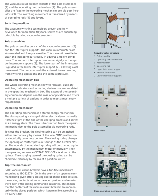
The arc extinguishing chamber adopts air insulation, which can be freely contacted and the insulation components are easy to clean in harsh environments;
The upper bracket of the arc extinguishing chamber is fixed, the lower bracket is axially guided, and the supporting components absorb external forces and contact pressure during opening and closing;
Maintenance free cycle: Under normal conditions (IEC 62271-1), it supports 10000 operating cycles without lubrication or adjustment.
Spring energy storage operating mechanism:
Energy storage method: electric energy storage (standard, motor voltage 24-240V DC/AC) or manual energy storage (with dedicated handle, order number 3AX15 30-4A/B/C);
Opening and closing control: remote electric (closing soleoid voltage 24-240V DC/AC), local mechanical/electric (to prevent accidental closing, switch equipment interlock needs to be connected);
Operation sequence: Supports standard sequence O-3min-CO-3min-CO (normal current), CO-30min-CO (short-circuit current), and some models support O-0.3s-CO-15s-CO (≤ 31.5kA).
2. Key functions and safety design
Free release mechanism: in accordance with IEC 62271-100, when receiving a disconnection command during the closing process, the contact immediately returns to the disconnection position and remains in place to avoid continuous disconnection (“pump effect”);
Interlocking system:
Electrical interlocking: The auxiliary contacts of the circuit breaker control the electromagnetic lock of the isolation switch, which can only be operated when the circuit breaker is opened;
Mechanical interlocking: detecting the position of the circuit breaker through sensors to prevent on load opening and closing, and adapting to drawer type components;
Release signal control: When the NO contact is opened, it instantly closes, triggering the alarm system. Local control requires a series cut-off switch (distinguishing between automatic/manual opening).
Technical parameters and environmental adaptation
1. Core electrical parameters (classified by voltage level)
Voltage level Rated lightning impulse withstand voltage (kV) Rated short-time power frequency withstand voltage (kV) Rated short-circuit breaking current (kA) Rated normal current (A) Pole distance (mm)
7.2kV 60/75 20/32 50/63 1250-4000 210/275
12kV 75/95 28/36 50/63 1250-4000 210/275
17.5kV 95/110 36/42 50/63/72 3150-8000 275/300
24kV 125/145 50/60 50/63/72 3150-8000 275/300
36kV 170/185/195 70/85/95 31.5/40 1250-4000 350
40.5kV 185/195 85/95 31.5/40 1250-4000 350
2. Environmental and installation restrictions
Climate environment: Complies with IEC 60721-3-3, with specific levels as follows:
Biological environment 3B1 is free from mold and insect erosion
Mechanical environment 3M2 anti vibration and impact
Chemical active substance 3C2 is resistant to slightly corrosive gases (without freezing/wind blown precipitation)
Mechanical active substance 3S2 requires regular cleaning of insulation components
Elevation and insulation correction:
When the reference altitude is 1000m, the insulation level needs to be corrected according to the altitude coefficient K a, with the formula: U ≥ U 0 × K a; Example: At 2500m, K a=1.2. If a 75kV lightning impulse withstand voltage is required, a 90kV reference insulation level should be selected.
Current carrying capacity: The reference temperature is 40 ℃ (for open type switchgear), and the rating can be increased when the temperature is below 40 ℃. For example, the carrying current of 6300A can be increased by about 15% at 20 ℃ (refer to the current temperature curve in the document).
Selection and Configuration Rules
1. Order number structure (16 digits)
Main circuit section (4-8 bits): Define voltage, short-circuit breaking current, rated current, pole spacing, for example:
3AH3 305-6:3 (main group), A (subgroup), H (series), 3 (version), 305-6 (36kV, 40kA, 2500A, 350mm pole spacing);
Secondary equipment section (bits 9-16): Define the combination of release devices, operating voltage, and auxiliary switches, for example:
9-position (release): A (1 shunt release), M (2 shunt releases+1 undervoltage release);
10 positions (closed soleoid): B (24V DC), F (220V DC), K (230V AC);
Option code: End with “- Z” and add a 3-digit code (e.g. Z A20:64 pole plug gold-plated).
2. Core options and auxiliary equipment
Option Category Model/Code Function Description Applicable Scenarios
Automatic tripping device with shunt release (connected to protective relay, 24-240V DC/AC) for overcurrent protection
When the undervoltage release voltage is less than 35% of the rated value, the circuit breaker (24-240V DC/AC) provides abnormal voltage protection
Current transformer operation release without auxiliary power supply, time division switch (0.5/1A rated current), remote and no power supply scenario
Auxiliary switch 6NO+6NC standard, providing regular control requirements for opening and closing status signals
12NO+12NC extended contacts, suitable for complex interlocking multi loop control
Connection interface 24 pole terminal block regular wiring (no plug) fixed installation
64 pole plug for quick insertion and removal, some interfaces can be customized with drawer style switch devices
Additional function Z A30 anti condensation heating (230V AC/50W) for high humidity environment
Z W70 warranty extended to 24 months for critical equipment
Z A70 3AH37 (5000A+) horizontal installation suitable for horizontal installation scenarios
3. Special configuration of generator circuit breaker (IEC/IEEE 62271-37-013)
Additional testing requirements:
Generator side fault: withstand high DC component (130%), no current zero crossing point;
System side fault: higher TRV rise rate, higher test voltage;
Split phase design:
Single pole independent packaging, suitable for 12500A/100kA scenarios, supports parallel operation;
Technical parameter example (17.5kV): Short circuit breaking current 50-90kA, DC component 45-130%, asymmetric breaking current 52-146kA.
Application and maintenance
1. Typical application scenarios
Industrial power distribution: Factory medium voltage power distribution system (high load current 6300A);
Generator protection: 3AH37/38 series (compatible with 17.5/24kV generators, capable of withstanding high DC components);
Special industries: refineries, extruders (harsh environments, compatible with 3C2 grade);
The 1PH7 series is an asynchronous motor developed by Siemens for the high-precision drive requirements of machine tools. It adopts a squirrel cage rotor design and has the characteristics of compact structure (short body), high power density, and low maintenance. It needs to be used in conjunction with the SINAMICS S120 drive system. The core parameters are shown in the table below:
Parameter Category Specification Range Key Explanation
The installation size and power level are determined by the shaft height (AH) of 100/132/160/180/225mm. The maximum power of AH225 is 205kW
Rated power (S1) 3.7-205kW, such as 3.7-10.5kW for AH100 and 205kW for AH228
The rated speed of a 4-pole motor at 500-2500rpm 50Hz is approximately 1500rpm
The maximum speed of AH100 can reach 12000rpm from 6500-12000rpm, and it needs to be matched with vibration level SR
Insulation level 155 (F), winding overheating ≤ 105K in an environment of 40 ℃
Protection level: motor IP55, fan IP54, dust/water spray resistant, flange side optional IP65 (with sealing ring)
Temperature monitoring stator winding with built-in KTY84 sensor and frequency converter for over temperature warning/shutdown protection
2. Operation mode and performance indicators
Supporting multiple operating modes, the power/torque output differences under different modes are as follows (taking AH132 as an example):
Typical application scenarios for power increase ratio in operation mode load cycle (10 minutes)
Detailed explanation of mechanical characteristics
1. Cooling system
Cooling method: External ventilation (compliant with EN 60034-6), fan axial installation at the non drive end (NDE), standard wind direction is NDE → drive end (DE), optional DE → NDE reverse direction;
Fan parameters: 3AC 400V/50Hz or 480V/60Hz, air flow rate 0.04-0.36m ³/s (e.g. AH100 is 0.04m ³/s, AH225 is 0.36m ³/s);
Environmental adaptation: When the ambient temperature is greater than 40 ℃ or the altitude is greater than 1000m, the power rating needs to be reduced by a coefficient. For example, when the altitude is 2000m or 45 ℃, the power rating should be reduced to 90% (refer to EN 60034-6).
2. Bearings and lubrication
Bearing configuration: Differentiated design based on shaft height and load type, with core parameters as shown in the table below:
Shaft height, driven mode, driven end bearing type, non driven end bearing type, maximum continuous speed (S1)
100 couplings/belts 6308 C4 deep groove ball bearings 6208 C4 deep groove ball bearings 5500rpm
160 coupling/belt 6312 C4 deep groove ball bearing 6212 C4 deep groove ball bearing 3700rpm
180 high radial force belt NU2214E cylindrical roller bearing 6214 C3 deep groove ball bearing 3000rpm
225 coupling 6216 C3 deep groove ball bearing 6216 C3 deep groove ball bearing 3100rpm
Lubrication requirements:
Service life lubrication (standard): AH100-160 bearing replacement cycle is 20000 hours, AH180-225 is 40000 hours (horizontal installation);
Oil lubrication (option K40): AH180 adds 15g of grease every 8000h, AH225 adds 25g of grease every 8000h, and the ambient temperature is 10 ℃ per liter, reducing the lubrication cycle by 50%.
3. Radial and axial force limitations
Radial force (FR): It needs to be calculated based on the speed and bearing life, for example, when AH100 is at 3000rpm and has a life of 20000h, the maximum radial force is 3000N; the belt driven scenario needs to meet the minimum radial force (such as AH180 being 3kN) to avoid abnormal bearing wear;
Axial force (FA): determined by external load, rotor gravity (such as AH228 rotor gravity of 2500N), and spring adjustment force (such as AH160 gravity of 800N), the calculation formula is:
Horizontal installation:F AZ=F A−F C Axis extends upwards:F AZ=F A+F L−F C(F A To allow axial force,F C For spring force,F LFor rotor gravity);Calculation example: AH132 horizontally installed,F C=600NIf there is an external axial forceF A=2000N, then axial force is allowed
F AZ=2000−600=1400N.
Electrical characteristics and component configuration
1. Electrical parameters and voltage characteristics
Frequency deviation: ± 2% (Class A),+3%/-5% (Class B);
DC bus voltage: compatible with SINAMICS S120 regulating power module, 400V grid corresponds to DC bus 600V, output voltage 425V;
Voltage limit characteristic: When the output voltage ≠ 425V, the characteristic curve needs to be shifted, and the formula is:
new original new original²,new original new original²;Example: When U-original=425V, P-original=22.6kW (6000rpm), and U-new=380V,new².
2. Encoder configuration
According to whether it comes with DRIVE CLiQ interface, the corresponding relationship between encoder type and order number is shown in the following table:
Interface type, encoder type, order number, 9th digit, core parameter
No DRIVE CLiQ, no encoder A-
No DRIVE CLiQ incremental encoder (sin/cos 1Vpp, with C/D signal) M 2048 S/R, 1 reference pulse per revolution
No DRIVE CLiQ absolute encoder (EnDat) E single turn 2048 S/R, multi turn 4096 rpm
Equipped with DRIVE CLiQ incremental encoder (22 bits, with commutation position), D resolution 4194304, built-in 2048 pulses/rev
Equipped with DRIVE CLiQ absolute value encoder (22 bit single turn+12 bit multi turn) F operating range of 4096 revolutions, suitable for high-precision positioning
3. Core options
Option Name Model/Code Function and Applicable Scenarios
Radial shaft sealing ring – DIN 3760 standard, upgraded protection level to IP65, compatible with ZF transmission
Transmission 2K120/2K250 planetary, transmission ratio 1:1/1:4, expanding constant power speed range
Moisture proof heating belt Q04/Q02 220V/100W, works when stopped to avoid winding condensation
Insulated bearing L27 non drive end bearing insulation, preventing damage from frequency conversion stray current
Extend warranty Q80 warranty period from standard to 24 months
Selection and installation specifications
1. Selection tools and processes
Core tool: SIZER software (order number 6SL3070-0AA00-0AG0), supporting steps:
Define driving tasks (such as spindle/feed drive);
Installation position: Supports horizontal (IM B3) and vertical (IM V1/V3), axial force needs to be recalculated when extending upwards/downwards;
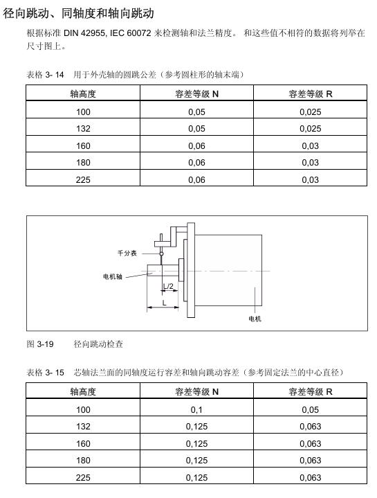
Concentricity requirements: Radial runout tolerance R level (0.025mm for AH100-132, 0.03mm for AH160-225), flange coaxiality tolerance R level (0.05mm for AH100);
Vibration control: vibration speed ≤ 2.8mm/s (level A), vibration level SR should be selected for exceeding the rated speed;
Wiring specifications: Power cables should avoid stretching/damage, DRIVE CLiQ interfaces should be anti-static (ESD protection), and external fan cables should be wired independently.
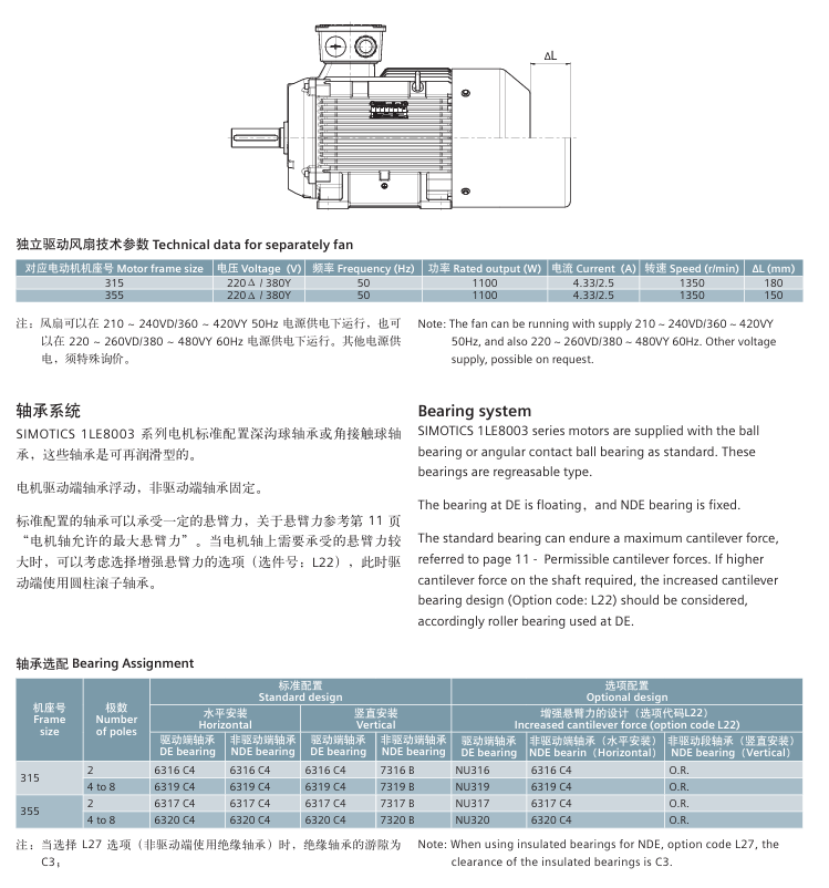
1. Series positioning and differences in sub series
The SIMOTICS 1LE8 series is a low-voltage high-power motor developed by Siemens specifically for the Chinese market. Based on a global design platform, it focuses on high reliability and high power density and is divided into two sub series. The core differences are shown in the table below:
Comparison dimension 1LE8003 (universal type) 1LE8033 (frequency conversion specific type)
Core use: General scenario (mainly direct supply, optional frequency conversion) Frequency conversion specific scenario (≤ 690V), suitable for steel, lifting, etc
Insulation usage level: 130 (B) for direct supply, 155 (F) for variable frequency, and 155 (F) for variable frequency operation
Bearing configuration: Deep groove ball/angular contact ball bearings (optional insulated bearings), standard insulated bearings (anti stray current damage)
Temperature protection optional PTC/PT100/PT1000 standard dual group PTC (145 ℃ alarm/155 ℃ trip)
Variable frequency voltage upper limit ≤ 460V ≤ 690V (optional N90 special insulation, no need for variable frequency filter)
2. Core rated parameters (50Hz)
Machine base number, pole number, rated power range (kW), rated speed (rpm), efficiency (4/4 load,%), power factor (4/4 load), weight (IMB3, kg)
315 2 220~315 2978~2982 95.8 0.89~0.91 1380~1590
315 4 220~315 1490~1491 96.0 0.85 1480~1650
315 6 160~250 990~991 95.8 0.85 1370~1700
315 8 132~200 740~741 94.0~94.6 0.80 1320~1690
355 2 355~500 2982~2988 95.8 0.89 2200~2300
355 4 355~500 1490~1491 96.0 0.85~0.87 1960~2290
355 6 280~400 993~994 95.8 0.85 2150~2270
355 8 220~315 743~745 94.6 0.81 2140~2250
Detailed explanation of mechanical characteristics
1. Structure and installation
Machine base and appearance: The machine base material is gray cast iron, standard color RAL7030 (stone gray), supports multiple installation structures (compliant with IEC 60034-7), and the core installation types and codes are as follows:
Installation type code (14th digit of order number) Applicable scenarios
IM B3 A machine base with feet, end cover without flange
IM B35 J machine base with feet, end cover with flange
The IM V1 G machine base does not have feet, and the end cover has a flange
Junction box: standard top mounted (order number 16th digit is 4), rotatable 4 × 90 °, supports upper right (5) and upper left (6) configurations; The 315 machine base contains 2 main inlet holes (M72 × 2), and the 355 machine base contains 3 main inlet holes, all of which are sealed with screw plugs. The maximum number of auxiliary terminals is 24 (L97 auxiliary junction box is required for excess).
2. Bearings and lubrication
Bearing configuration: The standard is deep groove ball bearings (6316 C4 for 315 machine base 2-pole, 6319 C4 for 4-8 pole; 6317 C4 for 355 machine base 2-pole, 6320 C4 for 4-8 pole), and 1LE8033 comes with insulated bearings as standard; The L22 enhanced design (with cylindrical roller bearings on the drive end) is available for high arm suspension scenarios.
Machine base number, pole number, lubrication cycle (h), amount of grease added (g)
315 2 3000 30
315 4 4000 40
315 6/8 6000 40
355 2 3000 30
355 4 4000 60
355 6/8 6000 60
Note: For every 10 ℃ increase in ambient temperature, the lubrication cycle is shortened by 50%.
3. Cooling method
Standard configuration: IC411 self fan cooling (radial centrifugal fan, independent of rotation direction);
Optional: F70 independent drive fan (recommended for low speed/over rated speed to reduce noise), the motor length increases by Δ L after installation (315 base+180mm, 355 base+150mm), and the fan parameters are 220V Δ/380VY, 50Hz, 1100W.
Electrical characteristics and protection
1. Voltage and frequency adaptability
Voltage deviation: Supports deviation between Class A (± 5%) and Class B (± 10%) of IEC 60034-1, with a temperature increase of approximately 10K for Class A and long-term operation not recommended for Class B;
Frequency deviation: Class A ± 2%, Class B+3%/-5%;
Core voltage configuration:
1LE8003:380VΔ/660VY、400VΔ/690VY(50Hz);
1LE8033: 500V Δ (standard), 690VY (options 0-6).
2. Motor protection
Winding protection: Supports PTC, PT100, PT1000 three types of components, and the selection corresponds to the 15th digit code of the order number:
Protection type code, number of wiring terminals, core parameters
Unprotected A —
Single set PTC (trip 155 ℃) B 2 three core series connection, suitable for heavy-duty starting
Dual group PTC (alarm 145 ℃/trip 155 ℃) C 4 1LE8033 standard configuration
3 2-wire PT100 H 6 with high precision and good linearity
1 2-wire PT1000 K 2 for more accurate temperature monitoring
Moisture protection: Options Q04 (1LE8003)/Q02 (1LE8033), 220V, 100W moisture-proof heating belt, works when stopped and closes when running to avoid winding condensation.
3. Characteristics of frequency conversion applications
1LE8003: Variable frequency voltage ≤ 460V, maximum safe speed 3600rpm (2-pole), frequency exceeding 60Hz requires special dynamic balancing;
1LE8033: Variable frequency voltage ≤ 690V, maximum safe speed 3600rpm (2-pole), peak voltage withstand value 3200Vpp (690V variable frequency), supports field weakening operation, and requires forced cooling when the load torque exceeds the limit.
Selection and Option Configuration
1. Order number rules (16 digit code)
Taking 1LE8003-3AA33-3 □□□□ as an example, the meaning of key positions is:
Explanation of the meaning of digits and example values
1-6 series identification 1LE800/1LE803
7 sub series 3=1LE8003, 3=1LE8033
8-9 aircraft seat number 3A=315, 3B=355
10 poles A=2, B=4, C=6, D=8
11-12 Voltage/Frequency 33=380V Δ/660VY 50Hz
13 iron core length 3=standard length
Installation type A=IM B3, J=IM B35
15 winding protection B=single group PTC, C=double group PTC
16 junction box position 4=top mounted, 5=upper right side, 6=upper left side
2. Core Option List
Option Number Function Description Applicable Scenarios
L22 enhanced cantilever force design (with cylindrical roller bearings at the drive end) for high radial loads (such as belt drives)
F70 independent drive fan running at low/over rated speed
H00 Rainproof Cover Outdoor Installation
Q04/Q02 moisture-proof heating belt (220V, 100W) high humidity/large temperature difference between day and night environment
L97 auxiliary junction box (2 M20 × 1.5 interfaces) with over 24 auxiliary terminals
H20 protection level upgraded to IP65 for dust/water spray environment
Typical application scenarios
1LE8003: General machinery (centrifugal fans, centrifugal pumps, air compressors), food and beverage production lines, and ordinary transmission equipment;
1LE8033: Variable frequency drive (steel rolling mill, crane, paper machine), variable speed load (adjustable speed fan/pump), harsh industrial environment.
Key issue
Question 1: What are the core differences between the LE8003 and 1LE8033 sub series? How to choose in the frequency conversion scenario?
Answer: The core difference between the two focuses on frequency conversion adaptability and protection configuration, and the selection should be based on the frequency conversion voltage, load type, and environmental severity
Comparison of core differences:
Comparison dimension 1LE8003 (universal type) 1LE8033 (frequency conversion specific type)
The upper limit of the frequency conversion voltage is ≤ 460V (with a filter added to the frequency converter end) ≤ 690V (optional N90 special insulation, no filter required)
Insulation usage level: 155 (F) for variable frequency operation, 130 (B) for direct supply, 155 (F) for all scenarios (optimized for variable frequency operation)
Optional insulated bearings (anti stray current) with standard insulated bearings (mandatory to avoid damage from frequency conversion stray current)
Temperature protection optional single group PTC/PT100 standard dual group PTC (145 ℃ alarm+155 ℃ trip, safer)
Suitable for frequency conversion scenarios with low voltage (≤ 460V), light load frequency conversion (such as fan speed regulation), high voltage (≤ 690V), and heavy load frequency conversion (steel/crane)
Selection logic:
If the variable frequency voltage is ≤ 460V, the load is universal speed regulation (such as fan/pump), and the budget is limited, choose 1LE8003 (additional insulation bearing option L27 is required);
If the variable frequency voltage is ≤ 690V, the load is heavy load/harsh environment (such as steel rolling mills, cranes), and high reliability is required, choose 1LE8033 (with standard insulated bearings and dual PTC protection, no additional configuration required).
Question 2: How to calculate the rated power derating of LE8 series motors in high altitude (>1000m) or over temperature (>40 ℃) environments? Please provide examples to illustrate.
Answer: In high-altitude/over temperature environments, the rated power needs to be adjusted through the power conversion factor k-HT, and the formula is:
P adm=P rated x k HT, where P adm is the allowable power, P rated is the rated power, and k − HT needs to be obtained from the table;
Example: Taking 1LE8003-3BA33 (355 base, 2-pole, rated power 355kW) as an example:
If installed at an altitude of 2500m and an ambient temperature of 45 ℃, the table shows k-HT=0.86, and the allowable power P ADM=355 × 0.86 ≈ 305.3kW; if installed at an altitude of 3000m and an ambient temperature of 50 ℃, k-HT=0.79, Allowable power P ADM=355 × 0.79 ≈ 279.5kW; note: After derating, it is necessary to ensure that the actual load power is ≤ P ADM to avoid motor overheating and damage.
Question 3: What are the configurations of the bearing system for LE8 series motors? How to choose a bearing scheme based on cantilever force requirements?
Answer: The bearing configuration is divided into standard and enhanced schemes, and the selection needs to match the size of the cantilever force at the shaft end (such as the load on the pulley and coupling):
Bearing configuration type:
Applicable scenarios for configuration scheme: Bearing type (drive end/non drive end) Maximum allowable cantilever force (example: 315 machine base 4-pole, N)
Standard solution (default) for ordinary loads (such as coupling transmission), deep groove ball bearings (6319 C4/6319 C4) with radial 7850N and axial 9290N (horizontal installation)
Enhancement scheme (L22) for high cantilever force (such as belt drive) cylindrical roller bearings (NU319/6319 C4) with radial lifting of 30%~50% (specific details need to be checked in the selection table)
Insulation scheme (L27) Frequency conversion scenario (anti stray current) Insulation deep groove ball bearing (INS. 6319 C4/…) Same as standard scheme, adding insulation layer
Selection logic:
Step 1: Calculate the actual cantilever force F Q=C × F U, where F U=2 × 10 7 × P/(n × D) (P is the rated power kW, n is the speed rpm, D is the pulley diameter mm), and C is the preload coefficient (flat belt=2, V-belt=2-2.5); Step 2: Compare the calculated value with the maximum allowable cantilever force of the standard solution: If F Q ≤ the standard value, choose the standard solution (no additional configuration required); If F Q>standard value, choose the enhancement scheme (L22) (replace the cylindrical roller bearing at the driving end);
If it is a frequency conversion scenario, regardless of the magnitude of the cantilever force, an insulation scheme (L27) should be added to avoid damage to the bearings caused by stray currents.
Example: The 315 base 4-pole motor drives a V-belt pulley (D=200mm) with a rated power of 250kW and a speed of 1490rpm,
F U=2 × 10 7 × 250/(1490 × 200) ≈ 1678NF Q=2.5 × 1678 ≈ 4195N < standard value 7850N, choose the standard solution.
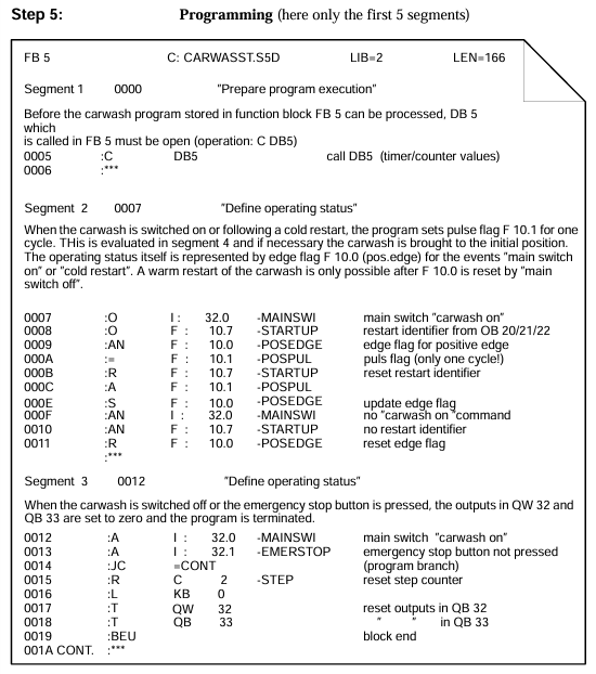
Software name: STEP 5 (full name SIMATIC Step 5 Programming Software), is a specialized programming tool developed by Siemens for the S5 series PLC. It was first released in the 1980s and later adapted to more S5 PLC models through version updates;
Version division: The main versions include STEP 5 V6.0 (supporting MS-DOS) and STEP 5 V7.2 (compatible with Windows XP), with the same functionality across different versions, except for differences in the operating environment;
Core value: As the “exclusive development platform” for S5 series PLCs, it provides full process support from program writing, parameter configuration to fault diagnosis, and is a key tool for the stable operation of traditional S5 systems.
Adapt PLC models and hardware requirements
Specific communication interface requirements for adapting PLC series models, software operation, hardware requirements (Windows XP)
S5-90U S5-90U CPU 928/929 MPI (requires MPI adapter 6ES7 972-0CA22-0XA0) Processor ≥ 1GHz, memory ≥ 512MB, hard disk ≥ 100MB
S5-100U S5-100U CPU 941/942 MPI/Profibus DP Same as above
S5-115U S5-115U CPU 943/944/945 MPI/Profibus DP Same as above
S5-135U S5-135U CPU 947/948 MPI/Profibus DP processor ≥ 1.5GHz, memory ≥ 1GB, hard disk ≥ 200MB
S5-155U S5-155U CPU 951/952/953 MPI/Profibus DP Same as above
Core functions and operations
1. Program creation function
Programming language support: Provides three industrial standard programming languages to meet different user habits:
Core advantages of programming language representation, applicable scenarios
STL (Statement Table) text instructions (such as A, O,=) have concise code and high execution efficiency, making them suitable for engineers with programming experience in complex logic
LAD (ladder diagram) graphical symbols (contacts, coils) are intuitive and easy to understand, close to electrical schematics, electrical engineers, and on-site maintenance personnel
FBD (Function Block Diagram) graphical function blocks (such as TIM, CTR) are suitable for modular programming and support complex process control scenarios such as PID
Program structure design: Adopting a “block structure” to organize the program, each block functions independently and can be called upon by each other, improving code readability and reusability:
OB (Organizational Block) program entrance, controlling the sequence of program execution (such as main loop, interrupt) OB1: Main loop block (continuous execution after PLC power on); OB2-OB15: Up to 16 interrupt blocks (such as timed interrupts and fault interrupts) (OB1-OB16)
FB (Function Block) user-defined logic module, can encapsulate duplicate logic (such as motor start stop control, counting logic) with parameters and background data blocks, up to 256 (FB0-FB255)
SB (System Block) Siemens preset functional modules, providing PID control (SB35), high-speed counting (SB40) and other functions depending on the PLC model (such as S5-115U supporting 32) without the need for users to write code
DB (Data Block) stores variable data and provides data support for FB/OB. Shared DB: Multiple blocks share data; Background DB: Only corresponds to FB with a maximum of 256 (DB0-DB255)
2. Online monitoring and debugging
Communication connection: Supports two mainstream communication methods to achieve bidirectional data exchange between software and PLC:
MPI (Multipoint Interface): Connected through MPI cables (such as 6ES7 972-0CA22-0XA0), with a maximum communication distance of 50 meters and up to 32 devices connected;
Profibus DP: Connected through a Profibus DP card (such as 6ES5 465-7LA11), with a maximum communication speed of 12Mbps, suitable for long-distance (1200 meters) communication.
Real time monitoring function:
I/O status monitoring: Real time display of the on/off status of input (I) and output (Q) on the LAD/STL/FBD interface (red=connected, gray=disconnected);
Internal variable monitoring: View the current values of flag (F), timer (T), and counter (C) (such as the remaining time of T3 and the count value of C5);
Program execution tracking: Through the “single step execution” and “breakpoint setting” functions, verify the program logic line by line and locate erroneous statements.
Online modification: Supports modifying non critical blocks (such as FB and DB) while the PLC is in RUN mode without stopping, ensuring production continuity; But the modification of OB1 (main loop block) requires switching to STOP mode.
3. Parameter configuration and fault diagnosis
System parameter configuration: Configure PLC hardware and system parameters through the “Hardware Configuration” function:
Hardware parameter I/O module address allocation, expansion module recognition, input module EM DI08 address set to I10.0-I10.7
Interrupt parameter interrupt priority (levels 1-15, with level 1 being the highest), interrupt trigger condition OB3 timed interrupt set to 100ms trigger, priority level 5
Timer/Counter Timer type (power on delay/power off delay), counter type (up/down count) T0 is set as power on delay type, C0 is set as up count type
Fault diagnosis function:
Diagnostic buffer: Automatically records two types of fault information, supporting users to quickly locate problems:
Program failure: syntax errors (such as address out of bounds), logical errors (such as dead loops);
Hardware failure: missing I/O module, communication interruption, power failure;
Status indicator light: The software interface displays real-time PLC running mode (RUN/STOP), communication status (green=normal, red=interrupted), and fault status (yellow=warning, red=serious fault).
Programming specifications and address ranges
1. Address allocation rules
The address of S5 series PLC adopts the “byte bit” format (such as I0.0), and the address range of each type is fixed, which must be strictly followed:
Address Type Address Range Bit Usage Description
Input (I) I0.0-I127.7 1024 bit to receive signals from external sensors, buttons, etc
Output (Q) Q0.0-Q127.7 1024 bit control external relays, indicator lights, motors, etc
Flag bits (F) F0.0-F127.7 1024 bits store program intermediate variables and logical states
Timer (T) T0-T255 256 to achieve delay control (such as T3 delay of 10s)
Counter (C) C0-C255 256 implements counting function (such as triggering action when C5 count value reaches 100)
Data block (DB) DB0. DBX0.0- DB255. DBX127.7 stores numerical data (such as temperature and pressure) with 32768 bits
2. Grammar Standards (Taking Common Languages as Examples)
STL (Statement Table): Combination of instructions and addresses, executed on a row by row basis, with one instruction per row:
Basic logic instructions: A I0.0 (normally open contact closed), O I0.1 (normally closed contact closed),=Q0.0 (output coil energized);
Timer instructions: L K5 (load delay value of 5s), T T3 (write value to timer T3), A T3 (delay timer T3 until the rear contact closes);
Counter instructions: L K10 (load count value 10), C C5 (write value to counter C5), A C5 (close contacts when counter C5 is full).
LAD (ladder diagram): Following the logic of “left power supply → contacts → coil → right power supply”, the contacts and coils are arranged graphically:
Normally open contact: The symbol is “┌——-“, corresponding to STL instruction A;
Normally closed contact: symbol “┌ -/-“, corresponding to STL instruction AN;
Output coil: symbol “– () –“, corresponding to STL command=.
Operation process and application scenarios
1. Complete operation process
Preliminary preparation:
Install STEP 5 software (Windows XP needs to run in “compatibility mode”);
Connect the PLC to the computer (one end of the MPI cable is connected to the PLC’s MPI port, and the other end is connected to the computer serial port/USB-MPI adapter);
Start the software and confirm the PLC model (such as S5-115U CPU 943) through the “PLC → Identify” function to ensure that the software is compatible with the hardware.
Program development:
New Project: “File → New Project”, name the project (such as “Production Line Control”), select the PLC model;
Create block: “Block → Create”, sequentially create OB1 (main loop block), FB1 (motor control block), DB1 (background data block);
Write command: call FB1 (CALL FB1, DB1) in OB1, and write motor start stop logic in FB1 (such as I0.0 start, I0.1 stop, Q0.0 control motor);
Grammar Check: “Edit → Syntax Check” to fix syntax errors (such as address errors and missing instructions).
Online debugging:
Download program: “PLC → Load Block”, select the block to be downloaded (OB1/FB1/DB1), confirm and download to PLC;
Switching mode: Switch the PLC from STOP mode to RUN mode, and the software interface displays a green “RUN” indicator light;
Monitoring and modification: Check the on/off status of I0.0/I0.1 on the LAD interface, use the “Modify” function to modify parameters in DB1 (such as motor running time), and verify whether the program logic is correct.
Maintenance management:
Program backup: “PLC → Save Block”, upload the program in the PLC to the computer and save it as a “. S5D” format file;
Troubleshooting: Check “Diagnosis → Buffer”, locate the problem based on the fault code (such as “E01: Address Out of Range”), modify the program or replace the hardware;
Program optimization: Adjust the logic according to on-site requirements (such as adding fault alarm function), re download and test.
2. Typical application scenarios
Traditional production line control: Based on S5-115U PLC and STEP 5, write production line logic programs (such as material conveying and assembly process control), and adjust production parameters (such as conveying speed) in real time through online monitoring;
Industrial machine tool control: On the S5-135U PLC, use STEP 5 to write machine tool processing logic (such as spindle start stop, tool switching), use FB blocks to package different processing processes, and improve program reusability;
Process control: For the chemical reaction kettle control system of S5-155U PLC, SB35 (PID control block) is called through STEP 5 to configure temperature/pressure control parameters and achieve high-precision process adjustment.
Product series: Siemens E50 series terminal power distribution products, covering the full scenario requirements of terminal power distribution, including protective devices and distribution boxes;
Background: In response to the increasing demand for electricity in modern buildings and the popularization of new electrical appliances, we provide safe, environmentally friendly, and compact terminal distribution solutions;
Target users: real estate developers, electrical design and construction units for civil/industrial/commercial buildings;
Core advantages:
Compact size: modular design, saving distribution box space, flexible wiring;
Green and environmentally friendly: produced in a green factory, compliant with RoHS standards, and contributing to carbon neutrality;
Safe and reliable: The full current range comes standard with a 6kA breaking capacity, and the circuit breaker is equipped with a safety window (to avoid the risk of contact adhesion) and supports isolation function.
Product family composition
Applicable scenarios for core functions of product categories
E50 miniature circuit breaker (MCB) overload, short circuit protection for lighting, air conditioning, and ordinary load circuits
E50 residual current protection circuit breaker (RCBO) overload, short circuit+residual current protection (anti electric shock) socket circuit (such as kitchen, bathroom)
Installation of Simbox series small distribution box components and integration of centralized management terminal distribution circuits
Core Product Technical Parameters
1. E50 series miniature circuit breaker (MCB)
Basic parameter table: | Parameter category | Specification details | Execution standard | GB/T 10963.1 | | Rated voltage/frequency | AC 230V/400V, 50/60Hz | | Rated current range | 6A, 10A, 16A, 20A, 25A, 32A, 40A, 50A, 63A | | Rated breaking capacity (Icn) | 6kA (standard across all current ranges) | | | Tripping characteristics | C-type (distribution protection, 5-10In tripping), D-type (power protection, 10-20In tripping) | | Number of poles | 1P, 2P, 3P, 4P | | Protection level | Direct installation: IP20; Installed in the distribution box: IP40 (according to EN60529) | | Wiring capacity | Hardwire: 1-25mm ² (25mm ² without voltage terminal); Flexible wire (with terminal): 1-16mm ² | | Tightening torque of terminal block | Maximum 2.5N · m | | Installation method | Modular structure, DIN rail clamp (35mm standard rail) | | Lifespan | Mechanical lifespan: 20000 cycles; Electrical lifespan: 10000 cycles | | Environmental adaptability | Temperature: -20~+55 ℃ (-5~+40 ℃ without capacity reduction); Altitude: 2000m; Pollution level: Level II | | Certification | CCC, RoHS|
Selection and ordering data (partial examples): | Rated current (A) | Number of poles | Tripping characteristics | Product model | Order number | Minimum order unit (only) | Minimum packaging quantity (only) | | 6 | 1P | C type | E50 MCB 1P C6A 6KA | 5TH61067CN | 12 | | 16 | 2P | C type | E50 MCB 2P C16A 6KA | 5TH62167CN | 6 | 6 | | 32 | 3P | D type | E50 MCB 3P D32A 6KA | 5TH63328CN | 4 | 4 | | 63 | 4P | D type | E50 MCB 4P D63A 6KA | 5TH 64638CN | 3 | 3|
2. E50 series residual current protection circuit breaker (RCBO)
Basic parameter table: | Parameter category | Specification details | Execution standard | GB/T 16917.1 | | Rated voltage/frequency | AC 230V, 50Hz | | Rated current range | 6A, 10A, 16A, 20A, 25A, 32A, 40A, 50A, 63A | | Residual current protection type | AC type (electronic, ELE) | | Rated residual operating current (I Δ n) | 30mA (instantaneous, anti electric shock) | | Rated breaking capacity | 6kA | Rated residual connection breaking capacity (I Δ m) | 2000A | | Tripping characteristics | C type, D type | Structural form | 1P+N (simultaneous protection of live and neutral wires) | | | Protection level | Direct installation: IP20; Installed in the distribution box: IP40 | | Wiring capacity | Same as MCB: Hard wire 1-25mm ², flexible wire (with terminal) 1-16mm ² | | Life | Mechanical life: 20000 times; Electrical lifespan: 10000 cycles | | Environmental adaptability | Same as MCB: -20~+55 ℃ (-5~+40 ℃ without capacity reduction); Altitude 2000m | | Certification | CCC, RoHS|
Selection and Ordering Data (Partial Examples): | Rated Current (A) | Tripping Characteristics | Product Model | Order Number | Minimum Ordering Unit (Only) | Minimum Packaging Quantity (Only) | | | 6 | C Type | E50 RCBO 1P+N C6A 30mA 6KA | 5TH83561CN06 | 6 | | | 20 | C Type | E50 RCBO 1P+N C20A 30mA 6KA | 5TH83561CN20 | 6 | | | | | | 6 | | | | | D Type | E50 RCBO 1P+N D16A 30mA 6KA | 5TH83562CN16 | 6 | 6 | | | | | 63 | D Type | E50 RCBO 1P+N D63A 30mA 6KA A | 5TH83562CN63 | 6 | 6|
E50 MCB/RCBO: It must be installed vertically, with DIN rail (35mm) card mounting, and the incoming line can be installed vertically or vertically;
Simbox distribution box: Concealed installation requires reserved wall openings (matching the concealed installation size), exposed installation requires fixing on a flat wall, and internal components are fixed through DIN rails;
Wiring specifications: Hard wires should be stripped to the appropriate length, and the terminal tightening torque should not exceed 2.5N · m to avoid false connections and heat generation.
Environmental restrictions:
Temperature: MCB/RCBO does not require derating within the range of -5~+40 ℃. If it exceeds this range, please consult the manufacturer; The distribution box is suitable for -5~+60 ℃;
Altitude: up to 2000m, exceeding which insulation performance needs to be evaluated;
Pollution: Only applicable to pollution level II (no obvious dust, corrosive gases).
Humidity: Relative humidity of 20% -30%, high humidity environment requires sealed packaging;
Other: It is prohibited to store it mixed with acidic liquids/gases or dust, and wiring should be avoided before use to prevent terminal battery effect corrosion.
Transportation requirements: light loading and unloading, avoid severe vibration, and transport in the same environment as storage conditions.
Typical application scheme
The manual provides standardized solutions for the power distribution needs of different residential units, with the following core configurations:
1. Small residential unit (2 bedrooms, electricity load 4KW, electricity meter 10 (40) A)
Circuit configuration: There are a total of 5 circuits with a total module of 10, using Simbox PS-Z 1 × 10 distribution box;