Call us 24/7uaedcs@163.com
Welcome to the official website of CNIACS Automation Technology Co., Ltd!
Call us 24/7uaedcs@163.com

GE V7768/V7769 hardware

Basic information

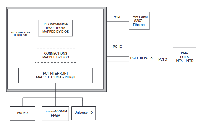
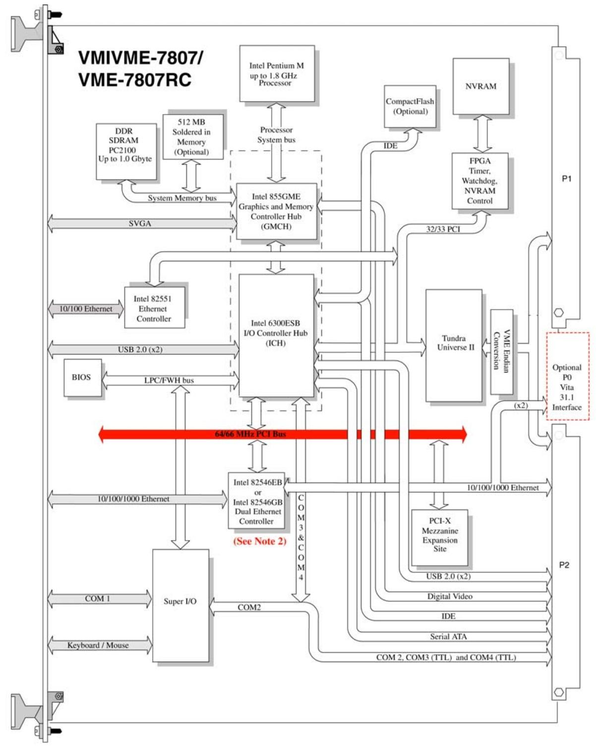
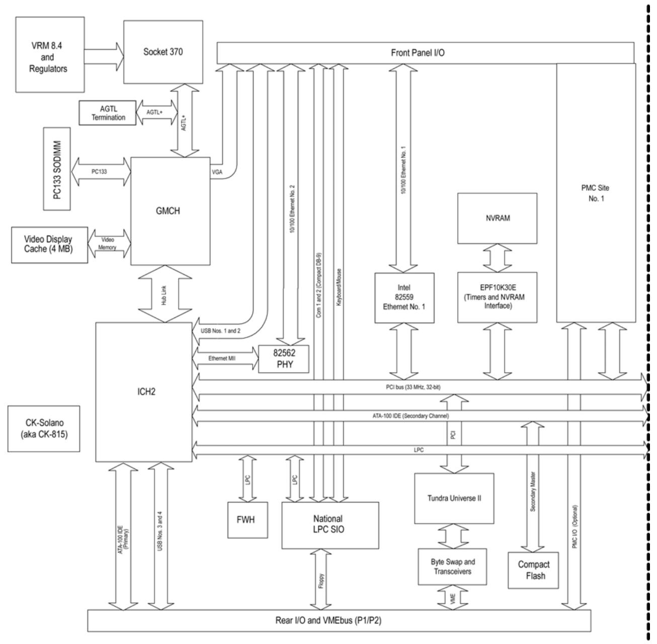
V7768/V7769 is a product launched by GE based on Intel ®  Core ™  The VME single board computer (SBC) with Duo processor adopts the dual slot, passive cooling VME Eurocard external specification, which complies with the current version of the EU RoHS directive (2002/95/EC). V7768 is equipped with Intel ®  Core ™  2 Duo or Celeron ®  The V7769 is a fully functional SBC equipped with an Intel Core 2 Duo processor, both of which use Intel’s 945GM chipset and ICH7-M I/O controller hub. When paired with a Celeron M processor, the front-end bus of the 945GM chipset is 533 MHz, and when paired with a Core 2 Duo processor, it is 667 MHz. Both comply with the VMEbus specification VITA 1-1994 and have transparent PCI to VME bridging capabilities.

Main functions and features

desktop function

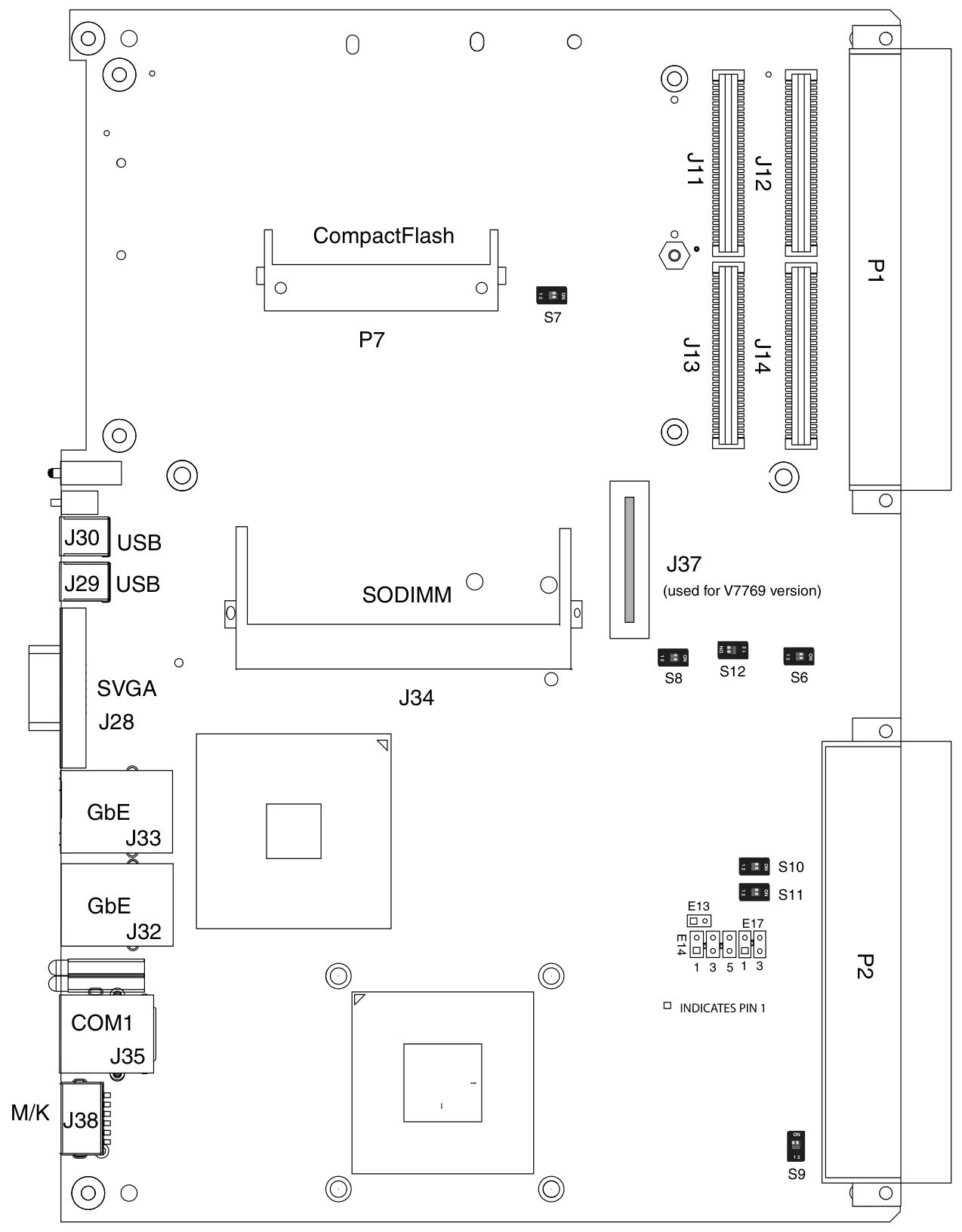
Processor and Memory: V7768 is equipped with Intel Core 2 Duo or Celeron M processors, while V7769 is equipped with Intel Core 2 Duo processors; In terms of memory, the maximum capacity is 2.0GB DDR2 SDRAM (one SODIMM).

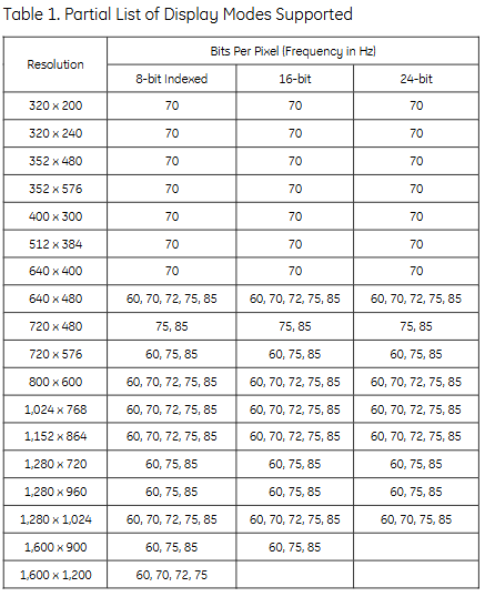
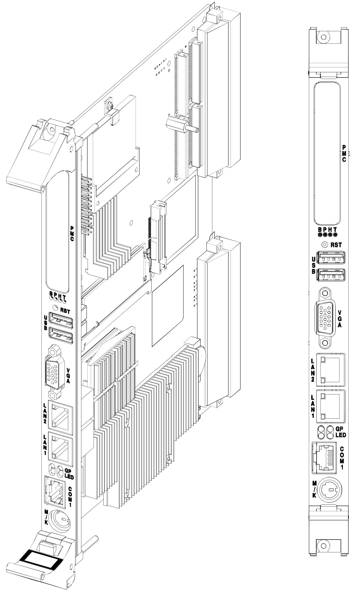
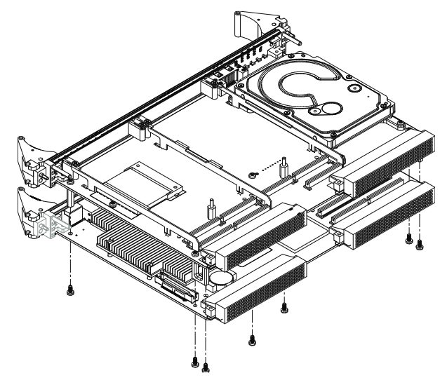
Display and Interface: Equipped with SVGA port (front I/O), dual Gigabit Ethernet (GbE) (front I/O), one RS232/422 COM port (front I/O), one RS232/422 COM support (rear I/O), two USB 2.0 ports (front I/O), four USB 2.0 supports (rear I/O), supports two SATA connections (rear I/O), V7769 can choose a 2.5-inch SATA hard drive, V7769 has unique dual SAS connectors (front I/O), etc.

Other: including real-time clock/calendar, front panel reset switch, PS/2 keyboard/mouse connection (front I/O), onboard parallel connector, etc.

Embedded functionality

Storage and Expansion: Supports remote boot from the front panel, up to 8GB bootable CompactFlash (optional), PMC site with PCI-X functionality (with VITA 35 P2 I/O, factory installed on V7768 and V7769 motherboards), etc.

Compatibility and Storage: Complies with VITA 1-1994 standard and supports byte swapping, 32KB NVRAM, optional watchdog timer with reset function, PMC expansion site.

Applicable scenarios: Suitable for various application scenarios such as telecommunications, simulation, instrumentation, industrial control, process control and monitoring, factory automation, automatic testing systems, data acquisition systems, etc.

Installation and setup

Unboxing and hardware setup

After opening the box, it is necessary to check whether the items have been damaged during transportation and pay attention to electrostatic protection.

Hardware settings involve various connectors, joints, and switches, such as VME interface connector (P1), USB 2.0 and other related connectors (P2), CompactFlash slot (P7), etc. Users can configure some jumper wires according to their needs, and factory configured jumper wires should not be modified by users. Modifying jumper wires that are not user configured will void the warranty and may damage the equipment.
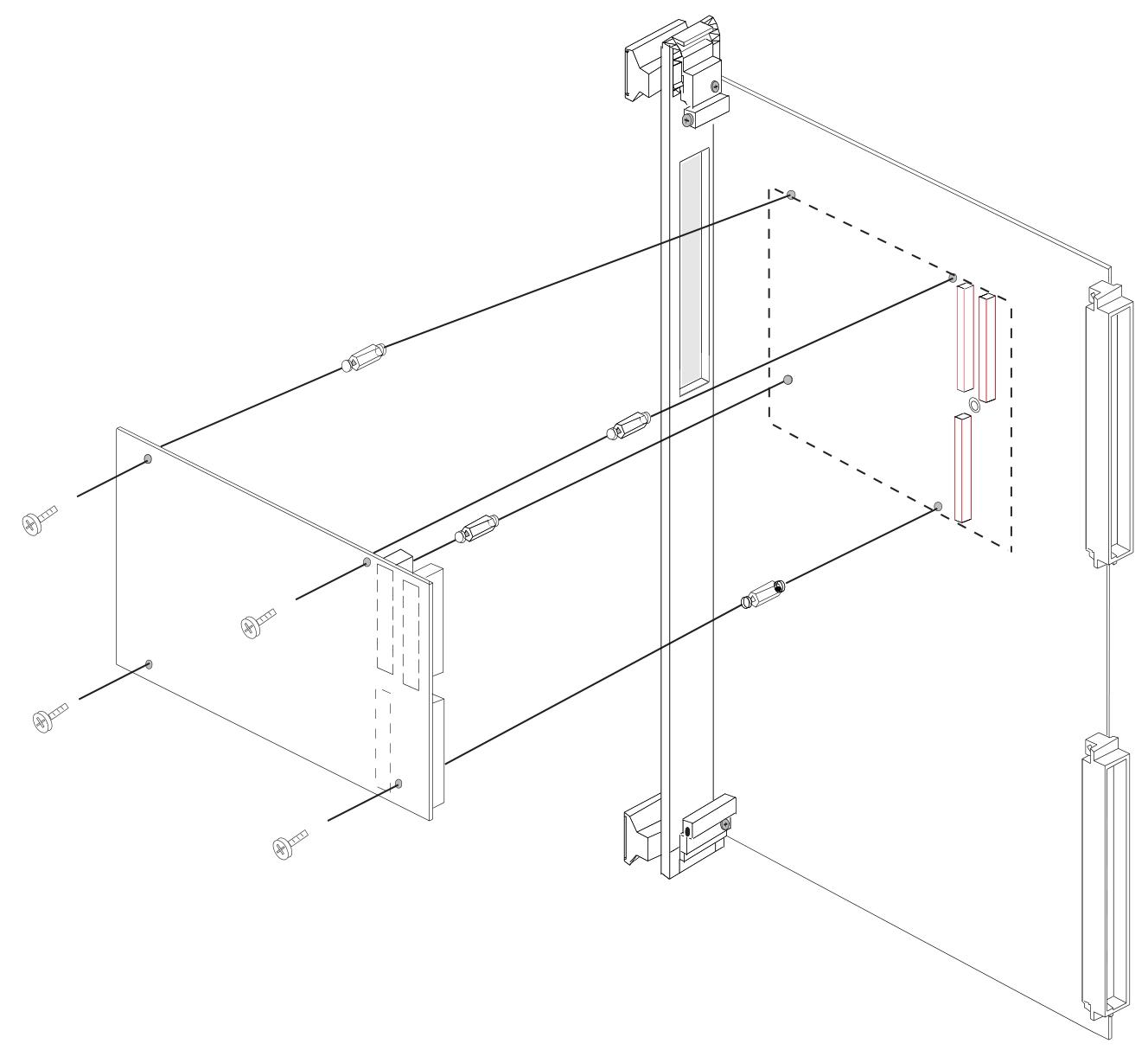
Installation steps

If using PMC module, connect it to V7768/V7769 before installing the motherboard, and refer to the product manual of PMC module for configuration and settings.

Insert V7768/V7769 into the system controller or peripheral slot of the VME chassis, ensuring proper alignment and secure installation.

The required peripherals can be accessed from the front panel or rear I/O, and each connector is clearly labeled. The detailed pin distribution can be found in Appendix A.

If the system is not pre configured, a keyboard and mouse need to be connected.

V7768 has an optional onboard CompactFlash disk, please refer to Chapter 3 “Embedded PC/RTOS Functions” for configuration details.

If an external driver module is installed, the BIOS setup program must be used to configure the driver type. Refer to Appendix B for proper system configuration.

If there is a driver module, install the operating system according to the manufacturer’s instructions.

BIOS settings

Entering the BIOS setup interface: Pressing the DEL key will enter the BIOS setup utility during system startup, which includes multiple menu options for detailed system configuration.

Main Menu: displays system information such as BIOS version, processor type, clock speed, and supports setting system clock and calendar. The configurable options in the menu are displayed in blue, while the options displayed in gray are not configurable. After selecting an item, its brief description will be displayed on the right side.

Advanced BIOS Setup Menu: Used to configure CPU settings, IDE bus, other external devices, and internal drives. Caution should be exercised during operation, as incorrect settings may lead to system malfunctions. If there is a problem after the change, you can select “Load Failed Safe Defaults” from the Exit menu and restart the system; If a system malfunction prevents access to the BIOS interface, you can refer to the “Installation and Setup” chapter to clear the CMOS.

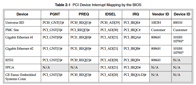
PCI/PnP Setup Menu: Used to control internal peripheral cards and various interrupts, as well as set the system’s plug and play functionality. Similarly, incorrect settings may cause system failures, and the solution is similar to the advanced BIOS settings menu.

Boot Setup Menu: You can set the priority of starting the device, including starting from a remote network. If the installed driver is not displayed in the menu, check the hardware installation. In addition, basic system related behaviors can be set, such as PS/2 mouse support and whether to use “Quick Boot”.

Security Setup Menu: Provides password settings for both Supervisor and User. If two passwords are used simultaneously, the administrator password must be set first. The system can be configured to require the user to enter a password every time it starts or enters ezPORT settings. When you forget your password, you need to clear the NVRAM and reconfigure it. Please refer to the “Installation and Setup” chapter for specific instructions.

Chipset Setup Menu: Used to select various options for the chipset in the system, such as CPU configuration and north-south bridge configuration. Due to the fact that chipset settings are processor related, extra caution should be taken when changing settings, following troubleshooting methods similar to those in the above menu.

Exit Menu: You can choose to save or discard changes and exit BIOS settings. If the previous BIOS settings cause system failure, you can select ‘Load Failed Safe Defaults’ from this menu and continue restarting.

First Boot Menu: Pressing the F11 key will enter this menu during startup, allowing users to choose to boot from a specific device at once, such as selecting ATAPI CD-ROM Drive when installing the operating system from a CD. This selection is only valid for the current boot. If you are unable to access this menu, you can disable QuickBoot Mode in the Main BIOS settings screen, save the changes, and try again.

GE VMIVME-7807/VME-7807RC Single Board Computer

Basic information

VMIVME-7807/VME-7807RC is based on Intel ®  Pentium ®  The VME single board computer (SBC) with M processor adopts the single slot, passive cooling VME Eurocard external specification and uses Intel technology ®  The advanced technology of 855GME chipset. Among them, VME-780RC aims to comply with the current version of the European Union (EU) Restriction of Hazardous Substances (RoHS) Directive (2002/95/EC).

Main functions and features

standard function

Processor and Memory: Equipped with Pentium ®  M processor, in terms of memory, using one SODIMM can provide 1.0GB DDR SDRAM, and you can also choose 512MB soldered in memory, with a maximum capacity of 1.5GB.

Display function: Built in SVGA controller (connected to the front panel), supporting multiple analog display resolutions; Equipped with a digital video controller (Rear I/O) DVI-D, supporting dual head display function and multiple digital display modes, with a maximum resolution of 1600 x 1200 x 256 colors (single view mode), and providing hotkeys for setting the display.

Network function: Includes 10/100 Mbit Ethernet controller (front panel connection) and dual Gigabit Ethernet supporting front panel or rear I/O, supporting 10BaseT, 100BaseTX, and 1000BaseTX Ethernet standards.

Interfaces and Ports: There are three serial ports (COM2, COM3, and COM4 located in Rear I/O), four USB 2.0 ports (two on the front panel and two on Rear I/O), Serial ATA (SATA) support (Rear I/O), serial port COM1 (front panel connection), Ultra IDE drive support (Rear I/O), etc.

Other features include real-time clock/calendar, front panel reset switch, miniature speakers, keyboard/mouse port (front panel connection), etc.

Embedded PC/RTOS functionality

Expansion function: Provide a PMC expansion slot (PCI-X, 66MHz) with front panel access; Optional P0 and VITA 31.1 interfaces.

Storage and memory: up to 2GB of CompactFlash (optional on auxiliary IDE), 32KB of non-volatile RAM.

Timer and Watchdog: Four software controlled general-purpose timers (two 16 bit and two 32-bit), as well as a programmable watchdog timer with reset function.

Other: Supports remote Ethernet boot and can execute multiple operating systems such as VxWorks ®、 Solaris ™  Or QNX ®  Wait.

Installation and setup

Unboxing and hardware setup

After opening the box, it is necessary to check whether the items have been damaged during transportation and pay attention to electrostatic protection.

Hardware settings involve various jumpers and switches, such as battery enable jumper (E3), system controller switch (S1), password clear/BIOS boot mode switch (S2), etc. Users can configure them according to their needs, but it should be noted that some factory configured jumpers should not be modified by users.

Installation steps

If using PMC module, connect it to VMIVME-7807/VME-7807RC before installing the motherboard.

Insert the board into the system controller or peripheral slot of the VME chassis, ensuring proper alignment and secure installation.

The required peripherals can be accessed through the transition module of the front panel or Rear I/O, which have different interfaces and functions.

If the system is not pre configured, a keyboard and mouse need to be connected.

If an external driver module is installed, the BIOS setup program needs to be used to configure the driver type.

If there is a driver module, install the operating system according to the manufacturer’s instructions.

BIOS settings

The onboard BIOS setup program controls many configuration options, which are stored in a special non-volatile, battery powered storage chip called the “CMOS configuration” of the board. For detailed settings, please refer to Appendix B.

Maintenance and Compliance

Maintenance

If the product malfunctions, it is necessary to first check the software, system configuration, electrical connections, etc. If it needs to be returned for repair, it is necessary to contact GE Fanuc Embedded Systems to obtain a Return Merchandise Authorization (RMA). User level maintenance is not recommended, and the drawings and charts in the manual are for reference only.

GE VMIVME-7750 Single Board Computer

Basic Overview

VMIVME-7750 is an Intel based device ®  Pentium ®  The VME single board computer with III processor has high performance and rich functions, suitable for various embedded system application scenarios.

Main characteristics

Processor and cache: using Pentium up to 1.26 GHz ®  III processor, equipped with 512 KB advanced transfer cache.

Memory: Supports up to 512 MB PC133 SDRAM through a single SODIMM.

Display function: Built in AGP SVGA controller with 4 MB display cache, supports multiple high-resolution display modes, up to 1600 x 1200 x 256 colors (single view mode).

Network function: Dual Ethernet controller, supporting 10BaseT and 100BaseTX interfaces, supporting remote Ethernet boot, using BootWare from Lanworks Technologies, Inc ®, Supports multiple network protocols.

Expansion function: Equipped with PMC expansion slot, supporting IEEE P1386 universal mezzanine card specification.

Storage function: Provides up to 1 GB of IDE CompactFlash memory, accessible through secondary IDE ports, and BIOS supports booting from Flash memory.

Interface and Port: Includes two 16550 compatible serial ports, supporting baud rates up to 115 Kbaud; Equipped with a combined PS/2 keyboard and mouse connector; Provide USB interface for the front panel dual connection hub host controller.

Timer and Watchdog: Equipped with two 16 bit timers and two 32-bit timers (excluding system timers), as well as software programmable watchdog timers.

Non volatile storage: 32 KB non-volatile SRAM that retains its contents in the event of a+5V power interruption or removal.

VMEbus interface: Based on Newbridge/Mundra’s Universe IIB high-performance PCI to VME interface, it has functions such as system controller, requester, mailbox, interrupt handler, etc., supporting multiple data transfer modes and byte swapping.

Ordering Options

Processor (A): Includes different specifications such as 733 MHz, 866 MHz, 1 GHz, 1.26 GHz, some with specific temperature ranges and heat dissipation devices.

SDRAM memory (B): There are options such as 64 MB, 128 MB, 256 MB, 512 MB, etc.

CompactFlash (C): Includes capacities of 64 MB, 128 MB, 256 MB, 512 MB, 1 GB, etc.

Other options (D, E, F): D and E are reserved for future use, while F is a special sales order related option.

Software support

Supports multiple operating systems, such as Windows ®  XP、Windows 2000、VxWorks ®、 Solaris ™、 QNX ®、 LynxOS ®  And Linux ®  Wait and provide corresponding board level support packages (BSP) and software tools, such as IOWorks ®  Software series, etc., facilitate application development.

Physical and Environmental Specifications

Size: 6U single slot Eurocard format, height 9.2 inches (233.4mm), depth 6.3 inches (160mm), thickness 0.8 inches (20.3mm).

Power requirements:+5VDC (± 5%), typical 6A, maximum 7A;+12VDC (± 5%), typical 105mA, maximum 200mA; -12VDC (± 5%), typical 50mA, maximum 75mA.

Working temperature: Standard 0 to 50 ° C, some options have extended temperature ranges such as 0 to 60 ° C, 0 to 40 ° C, 0 to 55 ° C, etc. Specific processors have corresponding air flow requirements.

Storage temperature: -25 to 80 ° C.

Relative humidity: 10% to 90%, non condensing.

Compatible Products

Can be used in conjunction with various GE Fanuc embedded system PMC and VME products, such as floppy disk/hard disk modules, CD-ROM modules, etc., to expand functionality.

GE FANUC S2K series independent motion controller

Equipment Overview

The FANUC S2K series is a high-performance standalone brushless servo or stepper amplifier series that integrates motion controllers and user configurable I/O functionality. The controller can be configured with a rotary transformer or a serial encoder motor feedback model. The encoder based S2K servo model can only be used in conjunction with GE Fanuc S series (SLM, SDM, or SGM) servo motors. The S2K rotary transformer feedback servo controller uses GE Fanuc MTR series (3N, 3S, or 3T) servo motors or third-party motors with appropriate ratings and rotary transformer specifications.

The servo model supports continuous stall torque of 0.84-478 in lb (0.095-54 Nm), while the stepper model supports holding torque of 144-3074 oz in (16.3-21.7 Nm). The servo controller model includes four 230 VAC ratings of 4.3, 7.2, 16, and 28 ampere continuous, as well as two 460 VAC ratings of 7.2 and 20 ampere continuous (the 460 VAC model only provides feedback for the rotary transformer). The peak current of the 230 VAC servo model is twice the continuous rated value, while the 460 VAC servo model is 1.5 times the continuous rated value. The rated value of the stepper controller is 5 amperes.

Support DeviceNet ™  The PROFIBUS communication model includes 14 discrete I/O points. 4.3 and 7.2 ampere servo models and stepper models can also provide 21 I/O points instead of DeviceNet or PROFIBUS communication. All drivers are capable of supporting Modbus/RTU protocol. If the optional Modbus adapter (product number IC800MBUSADP) is used, the standard RS-232 serial port can be used for multi-point applications. This adapter is an externally installed multi-point RS-232 to RS-485 serial port converter.

The S2K series controller is optimized for use with GE Fanuc S series or MTR series servo and stepper motors. If the motor and amplifier are not properly matched, overload and possible component damage may occur. Tables 1-1 to 1-3 show the recommended pairing of components.

The S2K series stepper controller requires a single-phase 115 VAC power supply. The S2K series servo controller models rated at 230 VAC and 4.3 or 7.2 amperes can operate on 115 VAC single-phase or 230 VAC three-phase, while all other models are rated for three-phase input. The 230 and 460 VAC models are designed to operate from three-phase power sources, but can be used with single-phase power sources.

The S series servo motors optimized for the S2K series controller range from 30 W to 5 kW and are rated at 230 VAC to achieve full speed. Using a 115 VAC power supply will result in a reduced operating speed of approximately half of the rated speed.

The 30 to 1000 watt S series servo motors (SLM models only), MTR-3S and MTR-3N series, and all stepper motor models are designed with standard NEMA shaft and flange mounting configurations for easy installation onto existing gear reducers and couplings. The 750 watt S series motor is installed with a super large shaft diameter (0.625 inches) for NEMA 34 to handle the peak torque rating of this model. The S series motor models ranging from 1 to 5 kW (except for the SLM100 1kW motor) and all MTR-3T series motors have metric installation configurations.

All servo motors can be equipped with an optional 24 VDC holding brake. These brakes are spring set, electrically released models designed to maintain static loads. The user must provide a separate 24 VDC brake power supply. The 30-750 watt S series motor has a pigtail cable with a box type connector for connecting the motor power supply, encoder, and brake. The 1000 to 5000 watt S series motors have MS style connectors, and the brake power supply (if needed) is integrated with the motor power supply in a common connector/cable. The MTR series servo motors include MS type connectors for brake power input. The MTR-3N and MTR-3T series brake motors integrate the brake power supply and motor power supply into the same cable. The MTR-3S brake motor requires a separate brake power cable (CBL-30-BT).

The S2K series controller is configured and programmed using Motion Developer software on a personal computer. This software is an independent application that works in the Machine Edition software environment, providing tools for beginners to simplify programming and direct code input for advanced users.

Hardware Overview

Specifications

S2K series controllers are used together with S series or MTR series servo and stepper motors. This chapter contains each specification of these components. Table 2-1 shows the available hardware resources on the S2K controller.

Electrical specifications of stepper controller

The S2K stepper controller (IC800STI105xx) is suitable for use on circuits that can provide symmetrical amperes up to 5000 rms and a maximum voltage of 130 volts, when protected by RK5 class 15A fuses. Table 2-2 summarizes the maximum continuous input power requirements for stepper controllers. The actual input power and current are functions of the motor operating point and duty cycle.

Electrical specifications of servo controller

The servo controller model is suitable for use on circuits that can provide symmetrical amperes up to 5000 rms and a maximum voltage of 250 volts, when protected by RK5 fuses. Table 2-3 summarizes the maximum continuous input power requirements. The actual input power and current are functions of the motor operating point and duty cycle.

Environmental Specifications

Working temperature: 32 to 122 ° F (0 to 50 ° C)

Storage and transportation temperature: -40 to 176 ° F (-40 to 80 ° C)

Altitude: 3300 feet (1000 meters)

Relative humidity (non condensing): 5 to 95%

S2K Communication Specification

Serial communication: 1 available port, supports multi-purpose programming port, format RS-232, maximum addressable unit is 1, communication rate is 1200, 9600, 19200 or 38400 baud, protocol is ASCII or Modbus/RTU (optional Modbus RS-485 multipoint port converter is available); Product Code IC800MBUSADP

DeviceNet communication network: 1 port per unit, supports I/O slave message passing, position controller configuration file, and explicit peer-to-peer message passing, with a maximum of 64 nodes, input power requirement of 11-25 VDC @ 40 mA maximum, communication rates of 125, 250, or 500 KBaud, drop line length of up to 20 feet, fine line trunk length of up to 328 feet, maximum 328 feet at 500 KBaud, maximum 820 feet at 250 Kbaud, and maximum 1640 feet at 125 Kbaud

PROFIBUS communication network: 1 port per unit, supports PROFIBUS configuration files, multicast, and broadcasting, with a maximum addressable unit of 100, no input power requirements, and a communication rate of 9600; 19,200; 45,450; 93,750; 187,500; 500,000; 1,500,000; 3,000,000; 6,000,000; Or 12000000 baud, the maximum length of the serial data link is 3936 feet at 9.6 KBaud

Input and output specifications

Digital input and output: The working range is 12-24 VDC, with a maximum of 30 VDC. The interface format is optical isolation, and the source/drain can be configured by the user. The maximum input turn off voltage is 4 VDC, the minimum on voltage is 10 VDC, and the load is 2 k Ω. The maximum output on resistance is 35 ohms, the maximum load current is 100 mA, and the maximum turn off leakage current is 200 nA. The capture input response time is 30 µ S

Analog inputs: 2 available, operating range+/-10 VDC, resolution of 12 bits, input impedance of 50 k Ω

Analog output: 1 available, user programmable or configurable for speed, current or tracking error, operating range+/-10 VDC, resolution of 8 bits, output current of 5mA

Encoder input and output specifications

Auxiliary encoder input: 1 available, input voltage is 5, 12 or 15 VDC, line receiver is 26LS33, input format is single ended or differential sine or square wave orthogonal, pulse/direction or CW/CCW pulse, maximum line counting frequency is 3 MHz (12 MHz orthogonal),+5 or+12 VDC power output capacity is 0.5 ampere each

Encoder output: 1 available, output voltage is 5.2 VDC+/-1%, line driver is 26LS31, output format is differential square wave orthogonal, pulse/direction or CW/CCW pulse (see Section 3.6.6 (Tracking source format selected by EOT parameters), marked pulse width is 1/5000 of encoder revolutions, maximum line count frequency is 3 MHz (12 MHz orthogonal)

Motor feedback input

Motor encoder input (based on encoder model only): 1 available, resolution of 2500 lines per revolution, line receiver of 26LS33, data input format of differential, square wave, orthogonal, commutation input format of serial (S-series motor), maximum line count frequency of 3 MHz (12 MHz orthogonal)

Motor rotary transformer input (based on rotary transformer model only): 1 available, resolution of 4096 pulses per revolution, maximum speed of 15000 RPM, type of control transmitter, phase shift of ± 5.0 degrees at 5kHz, zero voltage<20 mV at 5 kHz, transformation ratio of 0.5

Motor speed/torque curve

Contains curves for MTR series stepper motors/controllers, S-series servo motors/controllers, and MTR series servo motors/controllers, demonstrating the relationship between motor speed and output torque. The motor can operate continuously at any speed and torque combination within a specified continuous operating range.

Servo motor derating based on ambient temperature

The S series motor generates continuous torque as shown in the speed/torque curve (Section 2.2.2) within a certain ambient temperature limit, depending on the motor model. The following curve describes the continuous torque derating required for operation at ambient temperatures above this rated value and up to a limit of 40oC. The intermittent torque available for each motor does not require derating.

The MTR series servo motors are rated at an ambient temperature of 25oC and are mounted on 10 “x 10” x 0.25 “aluminum heat sinks. For motors operating at higher ambient temperatures, the continuous torque of the motor must be reduced as follows: continuous torque at ambient temperature, toC=rated continuous torque x (155-t)/130.

Sealing of servo motor

The design of S series and MTR series servo motors complies with IP65 protection level (excluding cable connectors on S series 30-750 watt models). All MTR-3N, MTR-3S, MTR-3T1x, MTR-3T2x, and 1-5 kW rated S-series motors include shaft seals as standard functionality, while 30-750 watt S-series motors, MTR-3T4x, MTR-3T5x, MTR-3T6x, and all stepper motors do not provide shaft seals. Adequate precautions shall be taken when installing the motor to ensure proper protection from excessive liquid and spray exposure.

Servo motor maintains brake

The servo motor can be equipped with an optional integrated parking brake. The brake is designed for fail safe operation and must be powered by a 24 Vdc power supply to release the brake.

NEMA motor installation

The MTR series and S series motors have installation configurations as shown in the table below. For dimensional information about these motors (including installation dimensions), please refer to the mechanical drawings in Chapter 3.

The MTR series stepper motors have standard NEMA shaft and flange installation configurations, as shown in Table 2-17 below. For the size information of these motors, please refer to the mechanical drawings in Chapter 3.

S series servo motor vibration test

These motors have two types of vibration tests, namely scanning test and resonance point test.

Scanning test: The motor undergoes a 5G variable frequency test on each of the three axes (X, Y, Z) for eight hours. For the purpose of these tests, the X-axis is parallel to the motor axis, the Y-axis is parallel to the encoder connector, and the Z-axis is at a 90 degree angle to X and Y. In this test, the vibration frequency increased from 20 to 3000 Hz within two minutes, and then decreased from 3000 to 20 Hz within two minutes. This pattern was repeated for eight hours.

Resonance point test: Firstly, identify the resonance frequency with the highest vibration when testing the motor in three directions (X, Y, Z) at a variable frequency of 5 G (20 to 3000 Hz). Then, the motor vibrates 10 million times in each direction (X, Y, Z) at the identified resonance frequency.

GE Hydran 201Ti (Mark IV) Transformer Monitoring Equipment

Equipment Overview

Hydran ™  201Ti is a small and easy to set up continuous dissolved gas analysis (DGA) monitor for oil, which can provide IEEE ®  The basic information used in standard C57.104 can serve as an important first line of defense for transformers, providing early warning of fault situations and reducing the risk of unplanned power outages. It adopts fuel cell technology (referred to as fixed instrument method 3 in the standard) and has two gas sensors to choose from: the world-renowned “Hydran composite gas” sensor (100% responsive to hydrogen and sensitive to carbon monoxide, acetylene, and ethylene) and the more basic “hydrogen only” sensor (focused solely on hydrogen production). This monitoring unit is installed on a single valve and uses dynamic oil sampling, without the need for pumps or additional pipelines to connect to different valves. Due to its simple function and easy to understand information, it has been one of the preferred monitoring devices for many years and ranks among the top in terms of installation volume among all DGA monitoring devices.

Main advantages

Continuously measure critical fault gases to understand the condition of the transformer.

Gas sensors can be selected: traditional “composite gas” sensors or more basic “hydrogen only” sensors.

Remote transmission of gas ppm and gas change rate values to avoid on-site visits and achieve remote monitoring.

The fourth generation design, which has undergone continuous improvement, has sold over 25000 units worldwide.

Application scenarios

Power company: Provide simple and effective solutions for less important transformers, focusing on and prioritizing asset replacement strategies.

Industrial factories: Reduce the risk of process interruptions caused by power failures and minimize costly production downtime.

Convenient asset supervision: permanently installed on a single transformer oil valve, without the need for additional pipelines or pumps; The “composite gas” sensor responds 100% to hydrogen gas (a common fault gas) and is sensitive to carbon monoxide (paper overheating), acetylene (arc), and ethylene (oil overheating), thus covering the main root cause of the fault; The ‘hydrogen only’ gas sensor is simpler and only responds 100% to general faulty gas hydrogen.

Configurable alarms

An alarm is triggered when abnormal levels of faulty gas are detected.

Two alert levels can be set (one for warning and one for alert) to display an increase in severity.

The alarm can be set at the gas ppm level or the hourly or daily gas change rate (ROC).

Automatic self check every 15 days, if a fault is detected (including power failure, oil valve closure, sensor or battery replacement), a service alarm will be triggered.

HMI

Backlit LCD display screen shows gas information.

A keyboard used to stop devices and confirm alarms.

GE’s highly acclaimed Perception ™ Software compatibility, downloadable, trend analysis, and analysis of transformer data.

Mark IV improvements

A thorough overhaul was conducted to improve the durability of the sensor, and new electronic boards and power supplies were used to comply with RoHS standards, while also enhancing the reliability and performance of the equipment.

Equipped with a local USB port, replacing the RS-232 port that is no longer available on most on-site laptops.

Adopting Modbus through isolated RS-485 ®  Protocol communication realizes the digital output of registers.

Controller

Hydran 201Ti can be connected to optional controllers to facilitate communication with multiple units and create local networks.

Ci-1 controller: a single channel controller that can replicate some human-machine interface functions (gas value display, alarm button). It is ideal when the 201Ti is installed in a difficult to reach position on the upper valve of the transformer. It can also lead out alarm relay contacts and analog outputs for easy wiring.

Ci-C controller: capable of receiving up to four 201Ti gas ppm data, providing a single communication point for all four monitoring instruments, without alarm relays or analog outputs, ideal for protecting 3 single-phase transformers and 1 backup transformer.

Through its RS-485 port, up to 32 controllers or 201Ti can be daisy chained, with a maximum chain length (total of all cables) of 1200 meters (4000 feet). All 201Ti connected to any daisy chained controller can be accessed through any controller in the local network, making communication easier, such as by installing only one RS-232 modem.

Technical specifications

Measurement: The fuel cell type sensor is located behind the breathable membrane in contact with the transformer insulation oil, with a measurement range of 25-2000 ppm (volume/volume, hydrogen equivalent), an accuracy of ± 10% reading ± 25 ppm (hydrogen equivalent), and a response time of 10 minutes (90% step change). The “composite gas” sensor has a 100% response to hydrogen gas and varying degrees of sensitivity to carbon monoxide, acetylene, and ethylene, with a repeatability of ± 5% of readings or the larger of ± 5 ppm; The “hydrogen only” sensor only responds 100% to hydrogen, with interference from carbon monoxide, acetylene, and ethylene at concentrations less than 3%, and a repeatability of ± 5% of readings or the larger of ± 10 ppm.

Function: Backlit LCD display screen (2 lines x 16 characters) with keyboard for setting devices and confirming alarms; The USB port (B-type connector) is used for local connection to the laptop configuration system, and the RS-485 (terminal block) is isolated to 2000 Vac RMS for connection to optional controllers and remote communication; Using Modbus via RS-485 ®  Or Hydran protocol outputs gas level (ppm) and gas change rate (ppm per hour or per day); Using 4-20mA output gas level ppm, ranging from 25-2000 ppm, maximum 10V load, isolated to 2000 Vac RMS.

Alarm: 3 different alarms (gas warning (Hi), gas alarm (HiHi), and service alarm (battery, sensor, temperature)), gas alarm can be set on the reached gas level or hourly or daily trend (gas level change rate), equipped with 3 dry touch point relays (Type C, SPDT),NO/NC, 3A@250Vac Resistive load, 3A@30Vdc Resistive load.

Manual sampling: an easily accessible external oil sampling port for glass syringes with a Ruhr plug.

Environment: The working environment temperature is -40 ° C to+55 ° C (-40 ° F to+131 ° F), and the working environment humidity is 0-95% RH (non condensing). When equipped with a finned radiator adapter option, the oil temperature at the valve is -40 ° C to+105 ° C (-40 ° F to+221 ° F), and the oil pressure at the valve is 0-700KPa (0-100psi) (vacuum resistant sensor).

Shell rating: NEMA Type 4X certified, compliant with IP56 requirements.

Power requirements: switchable between 90-132 Vac or 180-264 Vac, 47-63 Hz, maximum 475VA.

Mechanical parameters: cylindrical, can be installed on 1 “, 1.5” or 2 “internal thread NPT valves; The size is 178mm in diameter (7 “) x 180mm in length (7-1/8”); The installation weight is 5.6Kg (12lb); The transportation weight is 6.9Kg (15lb).

Option

Non NPT valve adapter; Fin heat sink adapter (1.5 “), used for ambient temperatures above 40 ° C (104 ° F) or oil temperatures above 90 ° C (194 ° F); Special pipe wrench for sensor installation and disassembly; H201Ci-1 single channel controller; H201Ci-C four channel controller; Accessories/options for the controller.

GE Hydran M2 (Mark III) Transformer Monitoring Equipment

Equipment Overview

Hydran ™  M2 is a continuous online dissolved gas and oil moisture monitoring device for transformers, which can alert staff of faults in transformers, provide critical monitoring information, and reduce the risk of unplanned power outages. By connecting additional sensors, more information can be obtained and correlated with DGA and moisture values for in-depth analysis of transformer status. Its data can be transmitted as raw data through various communication methods, and can also be transmitted using IEEE based methods ®  The on-board calculation of standard transformer mathematical models is converted into useful information.

Main advantages

Continuously measure the dissolved fault gases and moisture in the oil for early identification before potential problems develop into serious transformer faults.

Gas sensors can be selected: traditional “composite gas” sensors or more basic “hydrogen only” sensors.

Built in transformer model calculation based on IEEE standards (only applicable to mineral oil).

Multiple communication options and protocols for easy integration into SCADA or DCS systems.

The validated third-generation design has a large installation base worldwide.

Support new low flammability ester oils and mineral transformer insulation oils.

Application scenarios

Power company: Provide integrated solutions for important medium-sized transformers, focusing on and prioritizing asset replacement strategies.

Industrial factories: Reduce the risk of process interruptions caused by power failures and minimize costly production downtime.

Asset supervision: Easy to permanently install on a single transformer oil valve, without the need for additional pipelines or pumps, and can choose to input other sensors; Only hydrogen “or” composite gas “sensors are optional, where the” composite gas “sensor responds 100% to hydrogen (general fault gas) and is sensitive to carbon monoxide (paper), acetylene (arc), and ethylene (oil); The moisture sensor measures water in the oil, which is the result of insulation paper degradation (producing carbon monoxide and water) or gasket leakage.

Configurable alarms

When abnormal levels of faulty gas or moisture are detected, an alarm can be triggered with two alarm levels (one for warning and one for alarm) to indicate an increase in severity.

The alarm can also be set on the value of the optional analog input card or on the optional calculated transformer model.

Automatic self check every 15 days, and if a fault is detected (including power failure, oil valve closure, sensor failure), a service alarm will be triggered.

Mark III improvements

A thorough overhaul was conducted to improve the durability of the sensor, and new electronic boards and power supplies were used to comply with RoHS standards, while also enhancing the reliability and performance of the equipment.

Suitable for transformers using mineral insulating oil, now also suitable for ester oil (natural or synthetic).

GE’s highly acclaimed Perception ™ Software compatibility, downloadable, trend analysis, and analysis of transformer data.

Transformer model

Hydran M2 provides a mathematical model of mineral oil transformers based on IEEE standards and relevant to on-site experience. Using available sensor inputs, the received data is converted into useful real-time information to further understand the overall health status of the transformer. Possible model output examples include: estimating winding hotspot temperature, moisture content in paper, moisture bubble temperature, insulation aging, overload capacity, cooling efficiency, OLTC temperature difference.

Technical specifications

Measurement: including relevant parameters of composite gas sensors, hydrogen only sensors, and moisture sensors, such as measurement range, accuracy, response time, relative sensitivity, repeatability, etc.

Function: Equipped with a backlit LCD display screen (128 x 64 pixels) and a keyboard for setting devices and confirming alarms; Equipped with digital communication methods such as RS-232 port and RS-485, supporting multiple protocols; There are 5 different alarms that can be set on multiple parameters, equipped with 5 dry contact relays; Equipped with an easily accessible external oil sampling port.

Environment: The working environment temperature is -40 ° C to+55 ° C, and the working environment humidity is 0-95% RH (non condensing). When equipped with a finned radiator adapter option, the oil temperature at the valve is -40 ° C to+105 ° C, and the oil pressure at the valve is 0-700KPa (vacuum resistant sensor).

Shell rating: NEMA Type 4X certified, compliant with IP56 requirements.

Power requirements: 90-132 Vac or 180-264 Vac switch mode universal power supply, 47-63 Hz, maximum 650VA.

Mechanical parameters: It has a 1.5-inch NPT external thread and can be installed on 1-inch or 2-inch NPT internal thread valves using optional adapters; The size is 315 x 219 x 196 mm (12.4 x 8.63 x 7.72 inches); The installation weight is 7.5Kg (16.5lb); The transportation weight is 9.0Kg (20lb).

Option

Including finned radiator adapter, valve adapter, transformer model calculation (only applicable to mineral oil), analog input card, dual digital input card, analog output card, PSTN analog modem, GSM/GPRS wireless modem, network Ethernet communication using copper cable (RJ-45) or multimode optical fiber (ST), oil temperature sensor (magnetic, 4-20mA), split iron core load CT (4-20mA), ambient temperature sensor (4-20mA).

Installation Guide for GE Hydran M2 Transformer Gas

Product Overview

Hydran M2 is a transformer gas monitoring system launched by GE Energy, which is used to monitor the gas content (such as hydrogen) and humidity level in transformer oil in real time. By analyzing changes in gas concentration, the operating status of transformers can be determined, and potential faults (such as insulation aging, partial discharge, etc.) can be warned in a timely manner. The system supports network communication and can be connected to the monitoring center, suitable for online monitoring of various types of power transformers.

Safety Warning and Precautions

General safety requirements

Installation and maintenance must be carried out by qualified professionals, and the power station operator must be notified before operation to avoid triggering false alarms due to parameter modifications, power outages, etc.

The power cable needs to use a 2.08 mm ² (14-AWG) specification, with a maximum distance of 15 meters (50 feet) from the power source, and equipped with overcurrent protection.

Do not touch the sensor membrane, block the breathing hole, or puncture the breathing hole membrane to avoid damage to the sensor.

When installing, it should be placed horizontally, and tilting, vertical installation, or using bends are prohibited. Avoid installing on the inlet side of the radiator pump, bends, or accessory boxes.

Do not use high-pressure water flow to rinse equipment, spray paint, or clean sensors with solvents to avoid affecting monitoring accuracy or damaging equipment.

Multi language security warning

The manual is annotated with safety warnings in six languages: English, French, Spanish, German, Italian, and Swedish, emphasizing that unauthorized operations may result in equipment damage, property damage, or personal injury.

Installation process

1. Installation preparation

Tool preparation: GE provides tools including 3/16 inch hex wrenches, 1/16 inch and 5-32 inch hex L-shaped wrenches, wrenches, PTFE tape, etc; The installer needs to bring their own screwdriver, adjustable wrench, wire stripping pliers, water bucket, and cloth, etc.

Installation location selection: It is recommended to install on the straight section of the radiator return pipe (with good convective oil flow, low temperature, and easy maintenance). Alternative locations include the top oil injection valve, radiator top, and bottom drain valve (note the impact of oil flow on readings). During installation, it is necessary to ensure that the bottom clearance meets the requirements (84 mm space, see Figure 11).

2. Sensor installation

Separate the sensor from the housing: Remove the fixing screws and clips, carefully pull out the sensor, and disconnect the sensor cable (rotate the connector 1/8 turn and pull out).

Sensor sealing: Wrap PTFE tape around the sensor thread, manually install the sensor onto the valve, and tighten it with an adjustable wrench.

Exhaust operation: Ensure that the air release screw is located at the 12 o’clock position, slowly open the valve, exhaust the air inside the sensor (collect the oil into the water bucket), then tighten the air release screw and clean the residual oil.

Connecting the casing: Insert the sensor cable connector into the sensor, rotate and fix it, push the casing onto the sensor (to avoid squeezing the cable), install the clip and tighten the fixing screw.

Grounding treatment: Use 10-6 AWG copper wire to connect the housing grounding terminal to the grounding electrode.

3. Cable installation and wiring

Cable conduit: Install waterproof conduit fittings (1/2 inch NPT, PG-13, or M20), metal conduit must be grounded, and unused openings must be sealed.

Wiring terminals:

Analog input: Supports self powered, two-wire/three wire loop power supply sensors, connected according to terminal identification (see Figure 23-26).

Analog output: 4-20 mA or 0-1 mA output, connected to SCADA system (see Figure 27-29).

Alarm relays: 5 SPDT relays configured with software, corresponding to normally open, normally closed, and common terminals (see Figure 30).

Power supply: The AC power supply needs to be connected to the live wire (L), neutral wire (N), and ground wire (ground terminal), and equipped with a fuse holder (see Figure 31).

4、 Software configuration

User interface operation

Configure through the LCD display screen and buttons (Esc, Enter, directional keys, function keys), with menus including alarm settings, reading viewing, system settings, testing, service, etc. (see Figure 32-33).

Key parameter settings

Date and Time: Set in “Setup → Date&Time” to ensure time synchronization.

Sensor test: Execute in “Service → Gas Sensor Test” and there is no reading within 2 minutes after the test.

Shutdown process: It is recommended to exit all programs first, run “Backup” to save settings, and then restart or disconnect the power to avoid data loss.

Hardware and Interface

1. Core hardware configuration

Processor: Intel XScale PXA255 300 MHz.

Memory: 32 MB DRAM (divided into system, program, and storage memory), 32 MB Flash storage (including operating system and user program areas), 512 KB battery backup SRAM (data power off reserved).

Display:

10 “monochrome model: 640 × 480 resolution, 256 levels of grayscale, passive display.

12 “model: 800 × 600 resolution, color model supports 32768 colors, monochrome model supports 256 levels of grayscale, both are TFT active displays.

Touch screen: resistive, 12 bit resolution, supports stylus or finger operation, requires calibration to ensure accuracy.

2. Interfaces and extensions

Communication interface:

COM1: DB25 female interface, supporting EIA232 C/EIA485 standard, with a maximum speed of 115200 bps, can be used for serial communication or terminal simulation.

Ethernet: RJ45 interface, supports 10/100BaseT adaptation, includes 2 status LEDs, supports TCP/IP protocol and network connection.

CF card slot: Supports Type II Compact Flash cards, expandable storage or adding functional modules (such as wireless network cards).

Expansion bus: Built in expansion slot, supports optional expansion modules (requires opening the back cover for installation).

Other interfaces: 4 external USB 2.0 ports, 1 internal USB port, VGA display interface (12 “model including Display Port).

Software and Operations

1. Operating system and core functions

Operating System: Windows CE. NET 4.1, supports 32-bit applications, compatible with Windows series operating logic, simplifies development and operation.

Key tools:

Backup: Save the registry and desktop settings to Flash to ensure that the configuration is not lost after power failure.

Storage Manager: Manage storage devices (CF cards SRAM), Support repair or formatting.

System Information: Display device hardware, system version, and other information to assist in troubleshooting.

Pocket Internet Explorer: Browse web pages, supports JavaScript, can configure proxy servers and dial-up connections.

2. Network and Communication Configuration

IP address setting: Supports DHCP automatic acquisition or manual configuration, which needs to be set through “Network and Dial up Connections”.

Windows network access: Device name, user information, and domain need to be configured to access network shared resources through Windows CE Explorer.

GE 10 “/12” QuickPanel View

Product Overview

10 “/12” QuickPanel View is a compact industrial grade human-machine interface (HMI) computer based on Microsoft Windows CE. NET operating system, suitable for real-time monitoring and operation in factory workshops. It integrates a high-resolution touch screen, multiple communication interfaces, and expansion functions, supporting HMI application operation, data storage, and network communication. It has a sturdy and durable design that can adapt to harsh conditions such as dust and vibration in industrial environments.

Basic setup and installation

1. Hardware installation

Power connection: A 24VDC power supply (48W) needs to be connected and wired through the three screw terminals of a dedicated plug to ensure that the power supply has been disconnected before wiring.

Panel installation: It is necessary to cut openings on the installation panel that meet the size requirements (10 “model: 8.96” × 11.88 “; 12” model: corresponding size), and use the attached 10 mounting clips to fix them. The torque range is 2.6-4.4 inches/pound (0.3-0.5 Nm).

Protection requirements: After installation, it is necessary to ensure that the front panel sealing ring is intact to meet NEMA 4, 4X, and 12 protection levels (corresponding levels of panels or enclosures need to be matched).

2. Startup and shutdown

Startup process: After the first power on, the startup interface will be displayed, and after 5 seconds, it will automatically enter the Windows CE desktop. Basic parameters such as display, touch screen, clock, and network need to be configured, and “Backup” should be run to save the settings.

Shutdown process: It is recommended to exit all programs first, run “Backup” to save settings, and then restart or disconnect the power to avoid data loss.

Hardware and Interface

1. Core hardware configuration

Processor: Intel XScale PXA255 300 MHz.

Memory: 32 MB DRAM (divided into system, program, and storage memory), 32 MB Flash storage (including operating system and user program areas), 512 KB battery backup SRAM (data power off reserved).

Display:

10 “monochrome model: 640 × 480 resolution, 256 levels of grayscale, passive display.

12 “model: 800 × 600 resolution, color model supports 32768 colors, monochrome model supports 256 levels of grayscale, both are TFT active displays.

Touch screen: resistive, 12 bit resolution, supports stylus or finger operation, requires calibration to ensure accuracy.

2. Interfaces and extensions

Communication interface:

COM1: DB25 female interface, supporting EIA232 C/EIA485 standard, with a maximum speed of 115200 bps, can be used for serial communication or terminal simulation.

Ethernet: RJ45 interface, supports 10/100BaseT adaptation, includes 2 status LEDs, supports TCP/IP protocol and network connection.

CF card slot: Supports Type II Compact Flash cards, expandable storage or adding functional modules (such as wireless network cards).

Expansion bus: Built in expansion slot, supports optional expansion modules (requires opening the back cover for installation).

Other interfaces: 4 external USB 2.0 ports, 1 internal USB port, VGA display interface (12 “model including Display Port).

Software and Operations

1. Operating system and core functions

Operating System: Windows CE. NET 4.1, supports 32-bit applications, compatible with Windows series operating logic, simplifies development and operation.

Key tools:

Backup: Save the registry and desktop settings to Flash to ensure that the configuration is not lost after power failure.

Storage Manager: Manage storage devices (CF cards SRAM), Support repair or formatting.

System Information: Display device hardware, system version, and other information to assist in troubleshooting.

Pocket Internet Explorer: Browse web pages, supports JavaScript, can configure proxy servers and dial-up connections.

2. Network and Communication Configuration

IP address setting: Supports DHCP automatic acquisition or manual configuration, which needs to be set through “Network and Dial up Connections”.

Windows network access: Device name, user information, and domain need to be configured to access network shared resources through Windows CE Explorer.

GE PACSystems RXi EP Box type Industrial Computer (IPC)

Product Overview

The GE PACSystems RXi EP Box type Industrial Computer (IPC) is a high-performance, ruggedized industrial computing platform designed for harsh industrial environments. It can run HMI, historical data recording, and analysis applications, achieving device level real-time control and plant wide system integration. As a mid-range product of the RXi series, its core features include high-performance computing, flexible scalability, high reliability, and low total cost of ownership (TCO).

Core Features and Advantages

Characteristic specific parameter advantages

High performance processors can be selected from Intel Celeron (1.4 GHz) and Intel Core i7 (1.7 GHz) to meet high-performance requirements such as big data processing and real-time operation of multiple communication ports, supporting industrial applications such as GE Proficy.

The fanless design adopts passive cooling technology, with no moving parts to reduce dust pollution, improve reliability in harsh environments, and reduce maintenance requirements.

Three Gigabit Ethernet ports for network and communication (two of which support IEEE 1588 and 802.1AS time synchronization); Optional WLAN (via Mini PCIe slot) provides flexible network deployment capabilities, supports deterministic data transmission, and meets industrial communication intensive applications.

Expansion capability: 1 low profile PCI Express slot, internal Mini PCIe slot; The Slim version includes one PCI Express x4 slot for on-demand addition of features such as wireless modules and dedicated interface cards, suitable for diverse industrial scenarios.

Storage options include 2.5-inch SATA hard drive/SSD (user replaceable), CFast card slot (supports booting and runs in parallel with built-in storage), SSD enhances shock and vibration resistance, and adapts to wide temperature environments; CFast cards facilitate quick deployment and data backup.

Reinforced design aluminum alloy shell, IP20 dustproof rating, supports wide temperature operation to optimize heat dissipation and durability, suitable for harsh conditions such as dust and vibration in industrial sites.

Technical specifications

1. Hardware configuration

Processor: Intel Celeron 1.4 GHz or Intel Core i7 1.7 GHz

Memory: up to 4 GB DDR3 (Celeron processor); Up to 4 GB DDR3 ECC (Core i7 processor, supports error checking)

Non volatile storage: 128 KB nv SRAM (Core i7 version only, used for storing procedure data)

Interface:

4 external USB 2.0 ports+1 internal USB 2.0 port

Display interface: VGA port; Core i7 version additionally includes Display Port

Indicator lights: power, SATA status, Ethernet link/activity, battery status, overheating alarm

Real time clock: compatible with RTC 146818, equipped with replaceable lithium battery

2. Environment and Power Supply

Working temperature:

Standard model: 0 ° C to+60 ° C (some models have 0 ° C to+65 ° C)

Expansion type: optional -20 ° C to+60 ° C, specific configuration (Celeron CPU+dedicated SSD) can support -40 ° C to+70 ° C

Storage temperature: -40 ° C to+85 ° C

Humidity: 5-95% @+40 ° C (no condensation)

Altitude: 15000 feet (4.5 km) during operation, 40000 feet (12 km) during storage

Power supply: 24V DC input (± 25% fluctuation), with overcurrent protection

3. Machinery and Safety

Size: 182 × 233 × 98 mm (height × width × depth)

Installation method: Supports flat installation and DIN rail installation (Slim version supports 70 ° tilt installation)

Safety certification: compliant with UL1950, CE Class A, FCC-A standards

image.png

GE AT868 AquaTrans ™  Ultrasonic water flowmeter

Product Overview

Core functions

AT868 is an ultrasonic water flow meter (supporting 1 or 2 channels) that measures water flow velocity, volumetric flow rate, and mass flow rate based on the principle of time difference. It is suitable for flow monitoring of single-phase fluids such as clean water and sewage. It emits and receives signals through ultrasonic sensors, calculates fluid flow velocity, and converts it into flow data, supporting real-time display, data recording, and multiple output methods (analog, pulse/frequency).

Main features 

Multi channel configuration: Standard 1 channel, optional 2 channels, improve accuracy by measuring average, difference, or sum through dual channels.

Flexible sensor types: Supports wet and clamp on sensors to meet different pipeline installation requirements.

Rich output and communication: equipped with 0/4-20mA analog output, pulse/frequency output (for total count), supports RS232/RS485 serial communication, compatible with PanaView ™ Software remote operation.

High adaptability: Suitable for pipe diameters ranging from 0.04 inches to 200 inches (1mm to 5m), with flow rates ranging from -40 to 40 feet per second (-12.2 to 12.2m/s), meeting the needs of industrial pipeline flow monitoring.

Installation and wiring

1. Installation points

Sensor location: It needs to be installed in a straight pipe section, with at least 10 times the upstream pipe diameter and at least 5 times the downstream pipe diameter without turbulence interference (such as valves, elbows); Prioritize installation on the side of the pipeline (to avoid gas accumulation at the top or slag accumulation at the bottom).

Electronic enclosure: Adopting NEMA 4X/IP66 protection level, suitable for indoor and outdoor installation, should be close to the sensor to shorten the cable length (supporting up to 1000 feet/300 meters).

Pipeline requirements: It is necessary to measure the outer diameter, wall thickness, material and other parameters of the pipeline and program them to ensure the accuracy of flow calculation.

2. Wiring specifications

Power supply: Supports 85-265VAC or 12-28VDC, requires an external power-off device (such as a switch) that complies with the EU Low Voltage Directive, installed within a range of 6 feet.

Sensor wiring: Plug in or clip on sensors are connected through coaxial cables, and the cable length needs to be matched (with an error of ≤ 4 inches for frequencies ≤ 2MHz and ≤ 0.5 inches for frequencies>2MHz).

Output wiring:

Analog output (0/4-20mA): Load resistance ≤ 600 Ω, used for transmitting flow signals.

Pulse/frequency output: used for total count or frequency proportional to flow, maximum load 3A@100VDC .

Communication wiring: RS232 is used to connect to PCs or printers, RS485 supports multi device networking, and must follow shielding grounding specifications to resist interference.

Programming and Settings

1. Basic parameter configuration

Channel activation: Activate the channel through the CHx ACTIV menu and select the sensor type (standard or special).

System parameters: Set the flow unit (such as gallon/minute, cubic meter/hour), total unit, and decimal places in CHx SYSTM, and optional mass flow rate (fluid density needs to be entered).

Pipeline and sensor parameters: Enter pipeline material, outer diameter, wall thickness, sensor frequency, path length (P), and axial length (L) in CHx PIPE. For clamp on sensors, lining parameters (material, thickness) also need to be set.

2. Advanced feature settings

Response time: Set the average measurement response time through the AVRG menu. It is recommended to select the “STATS” mode (fast response in steady state, fast tracking when flow changes).

Zero flow cutoff: Set a zero flow threshold (0-1 feet/second) in CHx I/O to avoid reading deviations caused by small fluctuations.

Tracking window: When the fluid sound velocity is unknown or fluctuates greatly, enable Tracing WINDOW to automatically track the sound velocity to ensure measurement accuracy.

Display function

1. Display screen and indicator lights

LCD display screen: A 2-line x 16 character LCD display screen that supports backlight adjustment and can display real-time measurement data, set parameters, and error codes.

Display content: It can be configured to display up to 4 parameters, including:

Flow rate (feet/second, meters/second)

Volume flow rate (such as gallons per minute, cubic meters per hour)

Accumulated total amount (such as total cubic feet, total cubic meters)

Diagnostic parameters (such as signal strength, sound speed, time difference, etc.)

Wheel display function: If multiple parameters are configured, the display screen will cycle at set intervals, with each parameter staying for a few seconds.

2. Display settings

Enter the settings menu:

Press [ESC]+[ENTER]+[ESC] to enter the user program.

Navigate to PROG → GLOBL → I/O → LCD, set the number of display parameters and specific parameters.

Parameter selection: Select the content to be displayed from the measured values (flow rate, flow rate) and diagnostic values (signal strength, sound velocity), supporting custom units (imperial/metric).

Contrast and brightness adjustment: Manually adjust through the potentiometer (CONT contrast, BKLT backlight) behind the panel to ensure clear visibility in different lighting environments.

Operation function

1. Totalizer Reset

Used to reset the accumulated traffic value to zero, supporting three methods:

Panel operation:

Enter the RESET menu and select YES to confirm the reset.

After resetting, the total amount of all channels will be reset to zero and accumulation will resume.

External switch reset:

Wiring should be done in advance (refer to the installation section) and configured as RESET in GLOBL-SYSTM → GATE OPTION.

Press and hold the external switch for 1 second, and the total amount will automatically reset to zero.

Software reset: via PanaView ™  The Clear Instrument Totalizers function of the software can be remotely operated.

2. Measurement pause and restart

Only supported through PanaView ™  Software operation:

Pause: Select Stop Measurement in Edit Functions → PAUSE MEASURMENT to pause the flow meter measurement and maintain the output signal at its final value.

Restart: Select Measure Flow to restore the measurement and update the output signal synchronously.

3. Diagnosis and Error Viewing

Diagnostic parameter display: Configure and display diagnostic parameters in GLOBL → I/O → LCD, including:

Upstream and downstream signal strength (SS up/SS dn, normal range 50-75)

Speed of Sound (SNDSP)

Time difference (DELTA T, normal ≤ 1 μ s)

Signal quality (Qup/Qdown, normal ≥ 1200)

Error code: The display screen directly shows error codes (such as E1 indicating weak signal, E3 indicating flow rate exceeding limit). You can refer to Chapter 5 of the manual to investigate the cause (such as sensor alignment deviation, bubbles in the pipeline, etc.).

Key operation and menu navigation

1. Button functions

ESC: Exit the current menu or cancel the operation.

ENTER: Confirm the selection or enter the submenu.

↑/↓: Up and down navigation menu options or adjust parameter values.

←/→: Move the cursor (used to locate the digit when modifying parameters).

2. Common menu paths

View real-time data: default display interface, press ENTER to cycle through preset parameters.

Enter programming mode: ESC → ENTER → ESC → PROG, configurable channel parameters, units, outputs, etc.

Calibration output: ESC → ENTER → ESC → CALIB, used for calibrating 4-20mA analog output or pulse frequency output.

4、 Precautions

Display refresh rate: By default, it updates with the measurement cycle (response time can be set through the AVRG menu, ranging from 0.1-99 seconds).

Total overflow: When the cumulative value exceeds the maximum range, E9: Totalizer Overflow is displayed, and the total amount needs to be reset or the unit needs to be expanded (such as changing from “gallon” to “million gallon”).

Search for products

Back to Top
Product has been added to your cart