Call us 24/7uaedcs@163.com
Welcome to the official website of CNIACS Automation Technology Co., Ltd!
Call us 24/7uaedcs@163.com

GE VersaMax ®  Programmable controller

Product Overview

VersaMax ®  It is a new generation control system launched by GE Intelligent Platforms, which has a “three in one” function and can be used as a separate PLC control machine, I/O substation (controlled by other main control devices through fieldbus), or form a distributed large-scale control system. The product design follows the principle of “Six Sigma” and meets multiple international standards such as UL, CUL, CE, etc. It has the characteristics of easy use, economic practicality, high reliability, and rich product structure.

Basic System Structure

Composed of six basic units:

CPU: executes user programs, controls local or distributed I/O modules, and communicates with other PLCs.

NIU (Network Interface Unit): Provides communication protocols for slave stations, connecting I/O modules and hosts.

I/O modules: including various types such as switch quantity, analog quantity, thermal resistance RTD, thermocouple TC, high-speed counter HSC, etc.

I/O base: supports I/O module installation, backplane bus communication, and on-site wiring, and module loading and unloading do not affect wiring.

Communication module: Supports network communication such as Genius, DeviceNet (master), Profibus DP (slave), etc.

Power supply and power auxiliary base: Provides power to the I/O module, and can be added as an auxiliary power supply when the load is insufficient.

Core components and features

CPU module

Supports multiple programming methods (ladder diagram, sequential function diagram, instruction statement, etc.), with functions such as high-speed counter and pulse width modulation output.

Built in RS-232 and RS-485 communication ports, some models (such as IC200CPUE05) have built-in Ethernet interfaces.

Provides program protection, fault diagnosis, and other functions, with a run/stop operation switch and LED indication.

The order number includes IC200CPU001 (34KB memory), IC200CPU002 (42KB memory), IC200CPU005 (64KB memory), etc.

NIU (Network Interface Unit)

Used to use I/O modules as I/O stations on communication buses, supporting multiple network protocols.

Ethernet NIU (IC200EBI001): Supports Modbus TCP and UDP/EGD protocols, with a 10/100Base-T interface.

DeviceNet NIU (IC200DBI001): As a DeviceNet slave, it supports multiple communication structures.

Profibus NIU (IC200PBI001): As a Profibus DP slave, it has a maximum baud rate of 12M.

Genius NIU (IC200GBI001): Connected to the Genius bus, supports redundant configuration.

I/O module

Switching module: including input, output, and hybrid modules, adapted to different voltage, current, and other requirements, supports hot swapping, and each circuit has LED indicators.

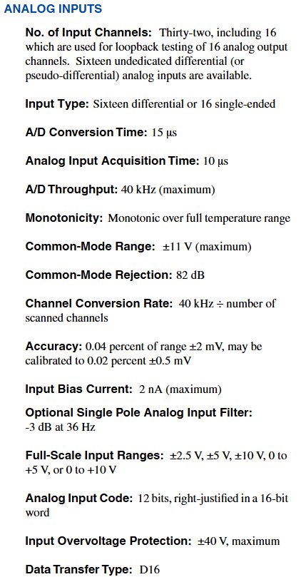
Analog module: receives current and voltage signals, processes RTD and thermocouple signals, has a resolution of 12-16 bits, and has isolation and other characteristics.

Partial hybrid modules integrate input and output functions, such as IC200MDD840 (20 point input+12 point relay output).

Power module and base

Power module: Provides 3.3V and 5V voltage, with AC and DC input types, and has functions such as short circuit and overload protection, such as IC200PWR001 (24VDC) and IC200PWR101 (120/240VAC).

Base: including terminal type, compact terminal type, connector type, etc., as well as auxiliary power base (IC200PWB001) and communication base (IC200CHS006).

Expansion module and communication module

Expansion module: By expanding the transmitter (IC200ETM001) and receiver (IC200ERM001/002) to expand the I/O rack, it supports multi rack and local two rack expansion.

Communication modules, such as Profibus DP slave module (IC200BEM002) and DeviceNet master module (IC200BEM103), enhance system communication flexibility.

Programming and configuration

Using VersaPro ™ Programming software (Windows environment) that supports hardware configuration, logic editing, online monitoring, and other functions.

The software supports multiple programming languages and protocols, and provides tools for error diagnosis. The order numbers include IC641VPH300 (including cables and converters) and IC641VPS300 (excluding).

Micro and Nano PLCs

Nano PLC: 10 point I/O, such as IC200NDD010 (6 inputs+4 outputs, 12VDC).

Micro PLC: expandable to 84 points, supports floating-point operations, high-speed counting, etc., such as IC200UDR001 (8 inputs+6 relay outputs).

Provide kit products, including PLC, programming software, cables, etc.

Environment and General Specifications

Environmental parameters: working temperature 0-60 ℃, storage temperature -40-85 ℃, humidity 5% -95% (no condensation), resistance to vibration, impact, etc. in accordance with international standards.

EMC characteristics: Compliant with CISPR 11/EN 55011 and other standards, possessing anti-static and radio frequency interference resistance capabilities.

GE VMIVME-7696 Pentium II processor based on VMEbus

Basic Product Information

Product type: VMIVME-7696 is a single board computer (SBC) based on the Pentium II processor, using 6U dual Eurocard format and occupying two slots. Please note that this product is not recommended for new designs, specifications have not been maintained, some options may be unavailable, and some information may be outdated.

Application areas: Suitable for simulation, instrumentation, industrial control, process control and monitoring, factory automation, intelligent networked PLC controllers, automatic testing, data acquisition, and other fields.

Core configuration and performance

Microprocessor: using Intel Pentium II processor (with MMX technology), with a speed of 333 MHz or 450 MHz, 32-bit addressing capability and 64 bit data bus, superscalar architecture allows for the execution of 3 instructions per clock cycle, with dynamic branch prediction unit, independent instruction and data cache, and built-in 512 KB level 2 cache (using dual independent bus architecture).

Memory configuration: Supports up to 512 MB of memory through a 144 pin SODIMM SDRAM module (only -6xx option supports 512 MB), with onboard DRAM and VMEbus dual port connection; Optional 8-96 MB flash memory (accessed through the secondary IDE port, BIOS supports booting from flash memory); Provide 128 KB battery backup SRAM, data can be retained during power failure, and can be accessed in PCI memory space.

Display function: Equipped with a 64 bit AGP SVGA controller, with 4 MB synchronous DRAM (64 bit high bandwidth data interface), supporting multiple screen resolutions, color counts, and refresh rates, such as 256 to 16 million colors at 640 x 480 resolution, refresh rates of 60-85 Hz, etc.

Interfaces and extensions

SCSI Controller: Onboard Adaptec 7880 PCI SCSI-2 controller, supporting 8-bit or 16 bit operations, with a speed of up to 40 Mbyte/s, providing SCSI I/O through VMEbus P2 connector, requiring the use of VMIAC-0561 SCSI adapter card.

Network interface: onboard DEC 21143 PCI Ethernet controller, supporting 10BaseT and 100BaseTX, accessed through RJ45 connector, using BootWare from Lanworks Technologies ®  Supports remote Ethernet boot and multiple protocols.

USB interface: The front panel has a Universal Serial Bus (USB) connection to the hub host controller, supporting functions such as isochronous data transfer and asynchronous message passing.

Serial and parallel ports: Two 16550 compatible serial ports, each with a 16 byte FIFO, supporting a maximum baud rate of 56 kHz; An enhanced parallel port that complies with the IEEE-1284 standard, with a 16 byte FIFO, and a data rate of up to 2 Mbyte/s in ECP mode.

Other ports: Standard PS/2 keyboard and mouse connectors, as well as small speakers for PC/AT sound output.

PMC Expansion: Supports IEEE P1386 universal mezzanine card specification, with 5V PCI mezzanine card expansion sites, supporting various commercial PMC modules such as fiber channel, reflective memory, analog and digital I/O.

VMEbus related functions

Interface features: Based on Newbridge/Mundra, Universe II high-performance PCI-to-VME interface supports VME64 mode, including A32/A24/D32/D16/D08 (EO)/MBLT64/BLT32, etc.

System Controller: Can be used as a slot 1 controller, supporting multiple arbitration modes (Round Robin, Single Level, Priority), providing SYSCLK driver, IACK * daisy chain driver, etc. The arbitration timeout can be programmed (16 or 256 µ s).

Requester and Interrupt: The microprocessor can request and obtain bus control through the VMEbus request line (BR3 to BR0), supporting multiple modes; The interrupt handler can monitor and respond to the VMEbus IRQ line, and the interrupt generator can issue interrupts through the VMEbus interrupt line (IRQ7 to IRQ1 *) under software control.

Byte order conversion: Built in real-time byte order conversion hardware (patent number 6032212), supports small and large data interfaces, and byte conversion for master-slave interfaces is controlled by software.

Master slave interface: The master interface provides 9 independent memory windows for mapping PCI transmission to VMEbus, and 8 independent memory windows for mapping VMEbus transmission to PCI bus from the slave interface. The window sizes have corresponding minimum and maximum values (0, 4 windows 4 Kbyte -4 Gbyte, etc.), and the slave interface windows can work in coupling or decoupling mode.

Enhanced bus error handling: It can read the VMEbus address that caused the bus error (in all modes), support bus cycle timeout and assert bus errors (regardless of whether it is a system controller), and can also be configured to assert interrupts after bus cycle timeout.

Featured Features

Timer and watchdog: Three 16/32-bit timers (compatible with 82C54) that can be mapped in PCI memory space and are fully programmable; Software programmable watchdog timer, timeout can be configured as reset through jumper, software can enable causing non shielded interrupt (NMI) or VMEbus SYSFAIL.

LED indicator lights and buttons: The front panel has 5 LEDs that display+5V power, VMEbus SYSFAIL status, IDE activity, etc; A small reset button that can reset the board, and if the system controller is enabled, it will also generate SYSRESET * on VMEbus.

Software support

Operating System: Supports multiple operating systems, including Windows NT/Windows 2000, VxWorks, Solaris, QNX, Linux, etc.

Software package: Provide corresponding Board Support Packages (BSP) for different operating systems, such as VMISFT-7418 (VxWorks), VMISFT-7417 (QNX), etc; There is also the IOWorks software family, such as VMISFT – 9420 VMEbus Access(Windows NT/Windows 2000)、VMISFT – 9450 IOWorks  Board drivers, as well as VMISFT-9406 IP VMEbus backplane drivers.

Physical and environmental parameters

Size: 6U dual Eurocard format, two slots, height 9.2 inches (233.4 mm), depth 6.3 inches (160 mm), thickness 1.6 inches (20.3 mm).

Power requirements:+5 VDC (± 5%), typical 7.5 A, maximum 12.0 A;+12 VDC (± 5%), typical 105 mA, maximum 200 mA; -12 VDC (± 5%), typical 50 mA, maximum 75 mA (when the serial connector is disconnected).

Working environment: Working temperature 0-55 ° C (requires forced air cooling, minimum 300 LFM), relative humidity 10-90% (no condensation), mean time between failures (MTBF) 36147 hours (217F standard).

Compatible Products

VMEbus products include floppy/hard disk modules (such as VMIVME-7452), SCSI terminal boards (VMIAC-0561), IDE/floppy disk conversion boards (VMIAC-0562), CD-ROM modules (VMIVME-7455), as well as various PMC modules, analog ADCs, analog outputs, digital input/output devices, enclosures, and power supplies.

GE VMIVME-7695 Single Slot Pentium II Embedded Module

Basic Product Information

Product type: VMIVME-7695 is a single slot (6U Eurocard format) VMEbus single board computer (SBC) based on the Pentium II processor.

Application areas: Suitable for simulation, instrumentation, industrial control, process control and monitoring, factory automation, intelligent networked PLC controllers, automatic testing, data acquisition, and other fields.

Core configuration and performance

Microprocessor: Adopting Intel Pentium II processor (with MMX technology), with a speed of 333 MHz, 32-bit addressing capability and 64 bit data bus, superscalar architecture allows execution of 3 instructions per clock cycle, as well as dynamic branch prediction unit, independent instruction and data cache, and built-in 512 KB level 2 cache.

Memory configuration: Supports up to 512 MB SDRAM through up to three 144 pin SODIMs, with onboard DRAM and VMEbus dual port connections; Includes 16 MB SanDisk IDE flash memory, with the option of M-Systems’ DiskOn Chip flash memory (available in 72, 144, or 288 MB options); Provide 32 KB battery backup SRAM, data can be retained in case of power failure.

Display function: Equipped with a 64 bit S3 Trio 3D AGP SVGA controller, with 4 MB SGRAM, supporting multiple screen resolutions, color counts, and refresh rates, such as 256 to 16 million colors at 640 x 480 resolution, refresh rates of 60-85 Hz, etc.

Interfaces and extensions

Network Interface: Onboard Fast Ethernet Controller (Intel 21143), supports 10BaseT and 100BaseTX interfaces, accessed through the front panel RJ45 connector, includes Lanworks Technologies’ remote boot BIOS, supports multiple protocols, but is not compatible with the DiskOn Chip flash option.

Serial and parallel ports: Two 16550 compatible serial ports with 16 byte FIFO, supporting up to 56 Kbps baud rate, using micro DB9 connectors; An enhanced parallel port that complies with the IEEE-1284 standard, comes with a 16 byte FIFO, and can achieve a data rate of 2 Mbyte/s in ECP mode, using a miniature DB25 connector.

Other ports: The front panel has PS/2 style keyboard and mouse ports (including Y-shaped adapter cable), dual USB ports, and small speakers for PC/AT sound output.

PMC Expansion: Supports IEEE P1386 universal mezzanine card specification, with 5V PCI mezzanine card expansion sites. PMC I/O can be accessed through VME64 P2 user-defined pins, supporting multiple commercial PMC modules such as fiber channel, reflective memory, analog and digital I/O.

VMEbus related functions

Interface features: Based on Tundra’s Universe II high-performance PCI-to-VME interface, supporting VME64 mode, including A32/A24/D32/D16/D08 (EO)/MBLT64/BLT32, etc.

System Controller: It can be used as a slot 1 system controller, supporting multiple arbitration modes (Round Robin, Single Level, Priority), providing SYSCLK driver, IACK * daisy chain driver, etc. It can automatically detect whether it is inserted into slot 1 and configure it automatically.

Requester and Interrupt: The microprocessor can request and obtain bus control through the VMEbus request line, supporting multiple modes; The interrupt handler can monitor and respond to the VMEbus IRQ * line, and the interrupt generator can issue interrupts through a broken wire in VMEbus under software control.

Byte order conversion: Built in real-time byte order conversion hardware (patent number 6032212), supports small and large data interfaces, and byte conversion for master-slave interfaces is controlled by software.

Master slave interface: The master interface provides 9 independent memory windows for mapping PCI transmission to VMEbus, and the slave interface provides 8 independent memory windows for mapping VMEbus transmission to PCI bus. The window size has corresponding minimum and maximum values, and the slave interface window can work in coupling or decoupling mode.

Featured Features

Timer and watchdog: Three 16 bit timers (compatible with 82C54) that can be mapped in the I/O space and are fully programmable; Software optional watchdog timer, timeout can be configured as board reset, non shielded interrupt (NMI), or no action, and VMEbus * SYSFAIL circuit can also be enabled.

LED indicator lights and buttons: There are 8 LEDs on the front panel, displaying power good status, thermal fault indicator, VMEbus SYSFAIL status, etc; A small reset button that can reset the board, and if the system controller is enabled, it will also generate SYSRESET * on VMEbus.

Enhanced Bus Error Handling: Provides more comprehensive bus error handling capabilities than Universe chips, such as the ability to read the VMEbus address that caused the bus error, support for bus cycle timeouts, and assert bus errors.

Software support

Operating System: Supports multiple operating systems, including Windows NT/Windows 2000, VxWorks, QNX, Solaris, Linux, Lynx OS, etc.

Software package: Provide corresponding Board Support Packages (BSP) for different operating systems, such as VMISFT-7418 (VxWorks), VMISFT-7417 (QNX), etc; There is also the IOWorks software family, such as VMISFT – 9420 VMEbus Access(Windows NT/Windows 2000)、VMISFT – 9450 IOWorks  Board drivers, etc.

Physical and environmental parameters

Size: 6U Eurocard format, single slot, height 9.2 inches (233.4 mm), depth 6.3 inches (160 mm), thickness 0.8 inches (20.3 mm).

Power requirements:+5 VDC (± 5%), typical 6.5 A, maximum 8 A;+12 VDC (± 5%), typical 105 mA, maximum 200 mA (when the serial connector is disconnected).

Working environment: Working temperature 0-55 ° C (requires forced air cooling), relative humidity 10-90% (no condensation), mean time between failures (MTBF) 101419 hours (Bellcore standard).

Compatible Products

VMEbus products include floppy/hard disk modules (such as VMIVME-7452), accessory headboards (such as VMIAC-0562), CD-ROM modules (VMIVME-7455), as well as various PMC modules, analog ADCs, analog outputs, digital input/output devices, chassis, and power supplies.

GE VMIVME-7459 Single Slot VME IDE CD-RW/Hard Disk Module

Basic Product Information

Product type: VMIVME-7459 is a multifunctional high-capacity storage module suitable for GE Fanuc embedded system series VME processors.

Form specification: Adopting a single slot (4HP) 6U external dimension, connected through VME P2 connector.

Features

Storage configuration: Provides multiple configurations, including writable CD and maximum 80GB hard drive storage, supporting one CD drive and one hard drive connected to a single IDE interface.

Compatibility of optical disc drive

The CD-RW drive options are compatible with various formats such as Photo CD, CD-I, Video CD, etc., and support multiple write formats such as Disc At Once and Track At Once.

The CD-ROM drive option supports multiple disc segments and is compatible with multiple disc types.

The DVD ROM option allows reading of media such as DVD ROMs, DVD Rs, and has both CD-RW and standard CD-ROM functionality.

Flexibility: Optional IDE hard drive, which can be configured as an IDE master or slave device through jumpers. It can be used as a CD only module, a hard drive only module, or in conjunction with other GE Fanuc storage modules (such as the VMIVME-7452 module with only floppy disks).

Ordering Options

A (CD drive option): 0=no optical drive/includes hardware; 1=Reserved; 2=Read and write CD drive; 3=DVD-R/CD-RW

B (hard drive/CompactFlash): 0=no hard drive/CompactFlash; 1-2, 4-9=reserved; 3=40GB IDE hard drive; 5=80GB IDE hard drive; G=1GB CompactFlash

C (cable configuration): 0=no cable; 1=Includes double slot cable assembly VMXC-2; 2=Includes three slot cable assembly VMXC-3; 3=Reserved; 4=Includes 14 inch cable assembly VMXC-H

D. E: Reserved (for future use)

F (Special Sales Order): 0=VME Standard Front Panel; 1=IEEE 1101.10 front panel; 2=VME standard front panel with conformal coating; 3=IEEE 1101.10 front panel with conformal coating; 4=Reserved

Connection and Cable

Connection method: Establish a connection with the IDE interface of a single board computer (SBC) through VME P2 user-defined pins.

Cable selection: Select cables based on the SBC module type and the physical layout of the VME chassis. In typical applications, single slot SBC can use dual slot VMXC-2 cable components; When adapting to a floppy disk module, use a three slot VMXC-3 cable assembly; When the dual slot GE Fanuc SBC or modules are not adjacent, it is recommended to use a 14 inch VMXC-H cable assembly.

Physical and environmental parameters

Size: 6U (4HP) single slot Eurocard shape, height 9.2 inches (233.25mm), depth 6.3 inches (160mm), thickness 0.8 inches (20.3mm).

User connector: VME standard 96 pin DIN P2 connector.

Interface: ATAPI/IDE.

Temperature: Operating temperature+5 ° C to+45 ° C, storage temperature -20 ° C to+60 ° C.

Humidity: 20% to 80%, no condensation, maximum wet bulb temperature of 29 ° C.

CD-RW transmission rate: 8X/8X/24X, typical random access time 130ms.

GE VMIVME-6016 VMEbus Intelligent 16 Channel Asynchronous

Basic Product Information

Product type: VMIVME-6016 is a single slot, 16 channel serial port controller belonging to the VMEbus device.

Core configuration: Equipped with onboard dedicated ring buffer (bidirectional for each channel), and a 25 MHz wait free 68020 microprocessor (also available in 32 MHz version). The VMEbus interface is controlled by the VIC068 VMEbus interface controller and the system controller function can be enabled through jumper wires.

Main function: The 68020 microprocessor handles the input/output and buffering of all character data, minimizing the cost of host driver programs. The user buffer can be configured as a ring buffer or a linear buffer, and can be located in onboard or VMEbus global memory.

Core functions and features

Channel characteristics: 16 channels are available in one VMEbus slot, and the line parameters of each channel are independently controlled by a control block in memory, including baud rate, internal ring buffer size, user buffer size, and address, among other parameters.

Connection and Signal: The front panel has RJ-11 6-pin telecommunications jacks for each channel, with signal levels compatible with RS-232. Each channel supports signal ground and five types of signals: TXD, RXD, RTS, CTS, and DCD.

Programmable features: covering baud rates (50 to 38400 bit/s), on-board and off board buffer sizes for sending and receiving, multiple flow control methods, special characters and related interrupts, send/receive BREAK and duration, error status monitoring, interrupts (priority, level, and vector), VMEbus addresses and modifiers, enabling/disabling VMEbus BERR timers, etc.

Performance parameters

Transmission rate: When using a 25 MHz CPU and the onboard buffer in a ring format, the maximum total transmission rate is 40000 characters per second; A 32 MHz CPU can reach 51000 characters per second in this situation. When using off board buffers (DMA access), the maximum total transfer rate is approximately 15000 bytes/second (depending on the access time of the storage device used), and any effective bit rate combination of 16 channels is valid as long as the rated total throughput does not exceed 30000 characters/second (300000 bits/second) (assuming the user buffer is configured as a ring buffer and located on the board).

VMEbus specifications

Slave: SAD032: SD32: MBLT (A32: A24: A16: AD0: D32: D16: D8 (EO)); MD64), A16 address base address can be selected through jumper, occupying 256 bytes; A32/A24 address base address is programmable, occupying 128, 256, 512, or 1024 Kbyte, allowing only super users or super users and non privileged users to access, interrupt level and vector programmable.

Host: MA32: MBLT32: MBLT (A32: A24: A16: D32: D16: D8 (EO): BLT; MD64), Bus request level 0, 1, 2 or 3, interrupt level and vector programmable.

Physical and environmental parameters

Temperature: Operating temperature from 0 to 65 ° C, storage temperature from -20 to 85 ° C.

Humidity: 20% to 80% relative humidity, no condensation.

Altitude: The working altitude can reach 10000 feet.

Cooling method: forced air convection.

Size: Dual height Eurocard (6U), 160 x 233.35mm.

Power requirement:+5 VDC, maximum 4.5 A.

GE VMIVME-5620 Intelligent HSD Simulator

Basic Product Information

Product type: VMIVME-5620 is an Encore HSD compatible HSD simulator, designed with dual Eurocard, and is a high-performance HSD interface device.

Connection method: Connect to Encore HSD/IBL interface or other HSD compatible devices through two 50 core flat cables with socket connectors at both ends.

Core components: Equipped with an integrated VMEbus interface (Cypress VIC068) and an onboard local bus with processor and memory, capable of interpreting host based I/O control block (IOCB) lists (IOCL).

Main functions and modes

working mode

HSD main mode: used to drive HSD peripherals, by interpreting the IOCL in the VMEbus global memory, sending external function commands to HSD peripherals, receiving device status, and transferring data blocks with devices. It also supports external mode, where HSD peripherals control the addressing and data transfer of VMEbus global memory.

HSD slave mode: It can be used as an HSD slave in a VME based computer or embedded controller, driven by an HSD host in another computer. The HSD host can be an Encore/Soul HSD on the SEL bus or another VMIVMME-5620 in the VME based computer.

IBL mode: allows two HSD compatible controllers (one of which can be an Encore HSD controller) to form a high-speed link without the need for cross cables and will re route some signals.

Featured Features

Can minimize host software overhead and execute a list of commands in memory.

Supports IBL compatible high or low priority, HSD external mode, data buffers (FIFOs), data and command chains, block transfer, 32-bit DMA transfer (via HSD bus).

As a VMEbus master-slave device, it supports command chain and data chain functions. The command chain enables the board to automatically execute the next IOCB in the list after completing the current IOCB execution, and only requires the host CPU to participate after the entire IOCB list is completed; A data link allows data to be passed in or out of non contiguous parts of memory.

Performance parameters

Transmission rate: The transmission rate between VMIVME-5620 is 4 Mbytes/sec (32-bit wide); The transmission rate from VMIVME-5620 to HSD depends on HSD, with a maximum of 3.2 Mbyte/s (the transmission rate may decrease due to factors such as cable length, operating mode, and VMEbus memory speed).

Transmission specification: The maximum block size is 256 Kbyte (16 bit transmission counter); Each HSD cycle has a transmission width of 32, 16, or 8 bits; The transmission mode is bidirectional half duplex; The address counter is 32-bit; Commands/controls come from a list in memory and support D32, D16, or D8 (EO) DMA.

VMEbus transmission

Slave: SAD024: SD32 A24: A16: AD0: D32: D16: D8 (EO), addressable at 64 byte boundaries through jumpers.

Host: A32: MBLT32 A32: A24: A16: D32: D16: D8 (EO): BLT, bus request level is 0, 1, 2 or 3, interrupt level and vector are programmable, bus authorization delay is 50 ns.

Hardware and Connection

I/O cable: Two 50 core (twisted pair flat ribbon) cables (not included in the product), VMIC recommends using high-quality twisted pair with overall shielding when the length exceeds 50 feet.

Maximum cable length: 250 feet.

System Controller Mode: When located in the first slot of the chassis, it can serve as a system controller with features such as SYSCLK driver, Iack daisy chain driver, level four bus arbiter (polling or priority), BERR timeout watchdog, etc. (only available as a system controller).

Physical and environmental parameters

Temperature: Operating temperature from 0 to 55 ° C, storage temperature from -20 to 85 ° C.

Humidity: 20% to 80% relative humidity, no condensation.

Altitude: The working altitude can reach 10000 feet.

Cooling method: forced air convection.

Size: Dual height Eurocard (6U), 160 mm x 233.35 mm.

Power requirements:+5 VDC, maximum 5.0 A, typical 3.5 A.

GE VMIVME-5588 high-speed reflective memory board

Basic Product Information

Product type: VMIVME-5588 is a high-performance, daisy chain VME to VME network high-speed reflective memory board that supports interrupt functionality.

Core function: Data transfer is achieved by writing data to the onboard global RAM, and the data is automatically sent to the corresponding memory locations of all reflective memory boards on the network, providing a fast and efficient way for data sharing between distributed computer systems.

Main performance parameters

Network speed and transmission rate: High speed and easy-to-use network, serial speed up to 1.2 Gbaud; The data transmission rate is 29.5 Mbyte/s when there is no redundant transmission, and 14.8 Mbyte/s when there is redundant transmission.

Node and Distance: Supports up to 256 nodes; The distance between multi-mode fiber optic connection nodes can reach 1000 feet, single-mode fiber optic is 10 kilometers, and dual axis cable is 30 meters.

Memory configuration: The onboard SRAM can be configured from 256 Kbyte to 16 Mbyte, with corresponding addressing boundaries for different memory options; Supports A24: A32: D32: D16: D8 memory access.

Access and cycle time: Write access time is 100 ns, read best case is 200 ns, read worst case is 400 ns; VME write cycle time is 200 ns (20 Mbyte/s), read best case is 320 ns (12.5 Mbyte/s), read worst case is 520 ns (7.7 Mbyte/s).

Features

Interrupt function: Any node can generate interrupts to any or all other nodes by writing byte registers. There are three user-defined interrupts with functions, priorities, and vectors; Interrupts follow data transmission and are only confirmed after data reception. FIFO can stack up to 512 interrupts.

Error management: Utilizing the error detection function of the fiber channel encoder/decoder and additional interleaved parity encoding and checking to detect errors; Assuming a light error rate of 10-12, the error rate of VMIVME-5588 is 1.3 × 10 ^ -10 transmissions, and the undetectable error rate is less than 1.64 × 10 ^ -20 transmissions; If a node detects an error, it will remove the erroneous transmission. If enabled, it will generate a VMEbus interrupt.

Redundant transmission mode: It can work in redundant transmission mode, where each transmission is sent twice, with priority given to the first transmission. If an error occurs, the second transmission is used, and if both transmissions fail, the transmission is removed. In this mode, the probability of both transmissions containing errors is extremely low.

Data protection: After error checking, the received data is placed in the receive FIFO, and after arbitration with VMEbus access, it is written to SRAM and send FIFO; To prevent FIFO overflow in design, a status register bit will be set and an interrupt may be generated when the FIFO is half full. If it exceeds half full, the VMEbus throttling mode will be activated; If the receive FIFO exceeds half full, VME access will be paused.

Other features: No need for a processor to participate in network operations, no processor overhead; Any node can reset any or all other nodes; Compatible with VMIVME-5578 software; Software addressable digital output bits for interface with VMIVME-5599 optical switch board or other user-defined purposes; There are bits in the status register used to verify whether data is being transmitted in the loop and to measure network latency.

Hardware and Connection

Board type: Two slot 6U VMEbus board.

Node identification: Each node has a unique identification number between 0-255, determined by jumper wires on the board during hardware system integration, and can be read by software by accessing onboard registers.

Cable options: There are multi-mode or single mode fiber optic, dual axis cable options; VMIC offers compatible multi-mode fiber optic cables (ST connectors, up to 1000 feet, etc.) and dual axis cables (9-pin D-type connectors, up to 30 meters, etc.), but does not provide single-mode fiber optic cables. The equipment is compatible with single-mode fiber optic cables (SC connectors, up to 10 kilometers).

Connection configuration: Adopting Daisy chain ring configuration, each transmission is passed in the ring until it returns to the source node. The node will retransmit the received non self initiated transmission and can insert its own transmission in the transmission gap.

Physical and environmental parameters

Temperature range: 0 to 65 ° C for forced air cooling operation, -40 to 85 ° C for storage.

Relative humidity: 20% to 80%, no condensation.

Mean Time Between Failures (MTBF): 88005 hours (217F standard).

Power requirement:+5 VDC, maximum 5.0 A.

GE VMIVME-5532L VMEbus fiber optic repeater link

Product Overview

VMIVME-5532L is a high-performance and easy-to-use VMEbus fiber optic repeater link that connects two or more VMEbus systems through fiber optic cables. The repeater link consists of a set of two boards (VMIVME-5532M as the motherboard and VMIVMME-5532S as the slave board), allowing the I/O board of a VMEbus slave located in one VMEbus chassis to be controlled by a VMEbus host located in another chassis, while supporting local control from a local VMEbus host in the chassis, achieving multi host functionality from the chassis.

Core functions and features

Key Features

Software transparency, direct communication from the host chassis to the slave chassis, no software overhead (one-way link control, two-way data transmission), supports plug and play operation.

In register enabled mode, in addition to basic functions, it also includes registers in the short I/O space that involve multi host operations from the chassis.

Supports 8-bit, 16 bit, and 32-bit data transmission, and supports 16 bit, 24 bit, and 32-bit addressing.

The VMEbus system is completely electrically isolated from each other, with fiber optic cables up to 6560 feet (2000 meters) in length.

Compared to standard repeaters, the advantages include compact cables, strong noise resistance, high voltage isolation, and no electromagnetic interference from cables.

Slave repeaters include bus arbitrators, bus requesters, system controllers, and control/status registers, used to operate and monitor slave chassis in redundant repeater links or multi host applications.

Features

Overview

The master VMEbus chassis can communicate with multiple slave chassis by using multiple relay links in a star configuration. Any VMEbus host in the host chassis can access (read or write) any slave board in the slave chassis, and only non interrupt slave boards are allowed in the slave chassis. When a VMEbus host (usually a CPU board) addresses any card in the slave chassis, the link between the host chassis and the slave chassis is automatically established. Whenever a host in the main chassis issues a VMEbus read/write cycle, it will be repeated to the slave chassis. If any slave board in the slave chassis responds to the address, data transfer (read or write) will occur between the chassis and a data transfer acknowledgement (DTACK) will be generated to the host (in the main chassis) to complete the cycle.

VMEbus compatibility

Compliant with VMEbus specification revised version C1, supporting A32, A24, A16, as well as D32, D16, D08 (EO). Among them, VMIVME-5532M is a DTB slave (used for the main chassis), and VMIVME-5532S is a DTB master (used for the sub chassis), both with dual height and single slot external specifications.

Arbitrator and Requester

Arbitrator: SGL

Requester: ROR, only supports bus request level 3 (BR3 *)

BG3IN * – BG3OUT * Maximum latency: 100 ns

BG3IN * – BBUSY * Maximum latency: 200 ns

Link register (available when enabled)

Including board recognition, burst mode, host bus authorization, VMEbus activity (slave chassis), burst mode key, VMEbus key, Sysreset enable key, slave chassis reset key, etc.

Repeat to the VMEbus signal from the chassis

A1 to A31, D0 to D31、DS0*、DS1*、WRITE*、SYSRESET*、SYSCLK、AM0、AM2、AM4、AM5、LWORD*  And IACK * (note: the following signals are regenerated from the chassis rather than sent through fiber optic cables: SYSCLK, AM0, AM1, AM3, and IACK *).

Return the VMEbus signal to the host box

D0 to D31, DTACK*

Active but non repetitive VMEbus signals from the chassis

BR0*-BR3*、BGIN0*-BGIN3*、BG0OUT*-BG3OUT*、BBSY*

Other parameters

Address modifier: 09, 0D, 29, 2D, 39, 3D

Read cycle overhead: maximum 4.0 µ s

Write cycle cost: maximum 4.0 µ s

Transmission rate (maximum) (10 foot cable length): Assuming the slave board in the chassis responds within 250 ns, with a minimum of 1MB/s (D32)

Cable specifications

Mode: Multi mode

Length: 5 to 6560 feet (1.5 to 2000 meters)

Fiber size: 62.5 microns

Package size: 125 microns

Buffer layer size: 900 microns

Maximum attenuation at 1300nm (including connector): 9.0 dB

Bandwidth at 1300nm: 500 MHz km

Protective cover length: 20 to 60 mm

U. L./NEC rating: OFNP

Connector style: ST, 2.5mm bayonet, both ends

Quantity required for each link: 2 (cables that meet this specification are provided with VMIVME-5532L. If you need to order cables separately, please refer to specification number VMICBL-000-F3-XXX)

Physical/Environmental Specifications

Size: Double height (6U) board 160 × 233.35 mm

Power requirements: VMIVME-5532S is a typical 2A at 5 VDC, with a maximum of 2.5 A; VMIVME-5532M is a typical 2A at 5 VDC, with a maximum of 2.5 A

Temperature: Operating temperature 0 to 65 ° C, storage temperature -20 to 85 ° C

Humidity: Relative humidity during operation is 20% to 80%, with no condensation

Altitude: up to 10000 feet (3048 meters) during operation

Cooling: forced air convection

Ordering Options

In VMIVME-5532L, A represents the type of fiber optic connector (0=ceramic core ST connector, 1=stainless steel core ST connector), and BC represents the cable length (00=no cable, 01=5 feet (1.5 m) and other options).

Only the VMIVME-5532M and VMIVMME-5532S cards have corresponding ordering options, with ABC of 000 (options reserved for future use).

The link includes one VMIVME-5532M (master) board, one VMIVME-5532S (slave) board, and two cable assemblies.

Connector data

Compatible connector: ST connector

Printed Circuit Board Fiber Optic Connectors: Fiber Optic Receiver HFBR-2416 (HP), Fiber Optic Transmitter HFBR-1414 (HP)

GE VMIVME-5531L VMEbus fiber optic repeater link

Product Overview

VMIVME-5531L is a high-performance and easy-to-use VMEbus fiber optic repeater link that connects two or more VMEbus systems through fiber optic cables. The repeater link consists of a set of two boards, allowing the VMEbus slave I/O board located in one VMEbus chassis to be controlled by a VMEbus host located in another chassis. The VMEbus chassis containing the VMEbus host is called the host chassis, while the VMEbus slave board is located in the slave chassis.

Core functions and features

Key Features

Software transparency, direct communication from the host chassis to the slave chassis, without software overhead (one-way link control, two-way data transmission).

Plug and play operation, supports 8-bit, 16 bit, and 32-bit data transmission (6U slave), supports 16 bit, 24 bit, and 32-bit addressing (6U slave), supports 8-bit, 16 bit data, 16 bit, and 24 bit addresses (3U slave).

The VMEbus system is completely electrically isolated from each other, with fiber optic cables up to 6560 feet (2000 meters) in length.

Compared to standard repeaters, the advantages include compact cables, strong noise resistance, high voltage isolation, and no electromagnetic interference from cables.

A VME to VME link consists of two boards and two fiber optic cables (motherboard: 6U, slave board: 6U or 3U).

Features

Overview

The master VMEbus chassis can communicate with multiple slave chassis by using multiple relay links in a star configuration. Any VMEbus host in the host chassis can access (read or write) any slave board in the slave chassis, and only non interrupt slave boards are allowed in the slave chassis. When a VMEbus host (usually a CPU board) addresses any card in the slave chassis, the link between the host chassis and the slave chassis is automatically established. Whenever a host in the main chassis issues a VMEbus read/write cycle, it will be repeated to the slave chassis. If any slave board in the slave chassis responds to the address, data transfer (read or write) will occur between the chassis and a data transfer acknowledgement (DTACK) will be generated to the host (in the main chassis) to complete the cycle.

VMEbus compatibility

Compliant with VMEbus specification revised version C1, supporting A32, A24, A16, as well as D32, D16, D08 (EO). Among them, VMIVME-5531M is a DTB slave (used for the main chassis), and VMIVME-5531S is a DTB master (used for the sub chassis).

Appearance specifications

Dual height, single slot: 5531M, 5531S

Single height, single slot: 5531S

Repeat to the VMEbus signal from the chassis

6U: A1 to A31, D0 to D31, DS0 *, DS1 *, WHITE *, SYSRESET *, AM2, AM4, AM5, and LWORD*

3U slave: A1 to A23, D0 to D15, DS0 *, DS1 *, WRITE *, SYSRESET *, AM2, AM4, AM5, and LWORD*

Return the VMEbus signal to the host box

6U: D0 to D31, DTACK*

3U: D0 to D15, DTACK*

Other parameters

Address modifier: (09, 0D), 3, 29, 2D, 39, 3D

Read cycle overhead: maximum 4.0 μ s

Write cycle cost: maximum 4.0 μ s

Transmission rate (maximum) (10 foot cable length): Assuming the slave board in the chassis responds within 250ns, with a minimum of 1MB/s (D32) (applicable to 6U)

Cable specifications

Mode: Multi mode

Length: 5 to 6560 feet (1.5 to 2000 meters)

Fiber size: 62.5 microns

Package size: 125 microns

Buffer layer size: 900 microns

Maximum attenuation at 1300nm: 9.0dB (including connector)

Bandwidth at 1300nm: 500MHz km

Protective cover length: 20 to 60mm

U. L./NEC rating: OFNP

Connector style: ST, 2.5mm bayonet, both ends

Quantity required for each link: 2 (cables that meet this specification are provided with VMIVME-5531L. If you need to order cables separately, please refer to specification number VMICBL-000-F3-xxx)

Physical/Environmental Specifications

Size: Dual height (6U) board 160 × 233.35mm, single height (3U) board 160 × 100.0mm (for slave only)

Power requirements: VMIVME-5531S and VMIVME-5531M are both typical 2A at 5VDC, with a maximum of 3.0A

Temperature: Operating temperature 0 to+65 ° C, storage temperature -20 to+85 ° C

Altitude: 0-10000 feet (3000m) during operation

Humidity: Relative humidity during operation is 20% to 80%, with no condensation

Cooling: forced air convection

Mean Time Between Failures (MTBF): 424895 hours, 431525 hours

Ordering Options

In VMIVME-5531L, A represents the slave specifications (0=6U slave, 1=3U slave), BC=00 represents unused, and D, E, F represent cable length and other information.

Only the VMIVME-5531M and VMIVMME-5531S cards have corresponding ordering options.

The link includes one VMIVME-5531M board, one VMIVME-5531S board, and two cable assemblies.

Connector data

Compatible connector: ST connector

Fiber optic receiver: HFBR-2416 (HP)

Fiber optic transmitter: HFBR-1414 (HP)

Printed circuit board fiber optic connector

GE VMIVME-4514A 16 channel scanning analog I/O board

Product Overview

VMIVME-4514A is a 16 channel scanning analog I/O board with built-in testing capabilities and P2 I/O connections. It provides 16 analog output channels and 16 analog input channels, with both input and output resolutions of 12 bits. Each channel of the analog output is designed with a sample and hold (S&H) output, and 16 analog inputs are digitized by a 12 bit analog-to-digital converter (ADC) controlled by a scanner, which can store data in dual port memory.

Core functions and features

Main functions

Continuously digitize all input channels and store the results in dedicated channel dual port registers (automatic scanning mode).

It has three A/D operation modes: automatic scanning mode when powered on, random polarization mode, and scanning polarization mode.

Supports P2 I/O connection, built-in onboard testing function, capable of testing 100% of active components.

Using semiconductor output switches does not affect accuracy (output impedance 0.1 Ω).

Analog input characteristics

16 single ended/differential (SE/Diff) analog input channels, 12 bit A/D converter.

Supports unipolar (0 to+10 V, 0 to+5 V) or bipolar (± 2.5 V, ± 5 V, ± 10 V) inputs.

A/D throughput of 40 kHz, optional low-pass filter, with overvoltage protection function.

Input relevant parameters: A/D conversion time of 15 µ s, acquisition time of 10 µ s, common mode range of ± 11 V (maximum), common mode rejection ratio of 82 dB, maximum input bias current of 2 nA, overvoltage protection of ± 40 V (maximum), data transmission type of D16.

Accuracy: 0.04% range ± 2 mV, can be calibrated to 0.02% ± 0.5 mV.

Analog output characteristics

16 sample and hold (S&H) analog output channels, 12 bit D/A converter.

The output has short-circuit protection and supports unipolar (0 to+10 V, 0 to 5 V) or bipolar (± 2.5 V, ± 5 V, ± 10 V) output.

The program can choose a scanning rate to provide better response for complex output functions, with an output current of 10 mA.

Output related parameters: resolution of 12 bits (per channel S&H), output impedance of 0.1 Ω, total error of 0.05% of full-scale range, and maximum setup time of 1.7 ms to reach 1 LSB.

Refresh update rate: default 550 Hz, fast refresh 1600 Hz (note: output refresh temporarily stops during input analog-to-digital conversion, so the output refresh rate decreases with the increase of analog-to-digital conversion rate. In the worst case scenario of automatic scanning mode, the default refresh rate is 300 Hz, and fast refresh is 900 Hz).

Operation Mode

Automatic scanning mode: Through power on system reset or program selection execution, all channels are continuously scanned, and digital data is stored in 16 16 bit dual port registers. It only needs to be read from the dual port registers without further programming.

Random polling mode: It is necessary to control the program to generate a single transition, and determine whether the transition is completed through the polling transition end status bit.

Scanning polarization mode: Perform a single scan of all channels, and determine whether the scan is complete through the polarization scan end control bit.

Other Features

Board address and VMEbus access

The physical address of the board can be selected through jumper wires on the board, and decoding the VMEbus address lines A06 to A15 is used for board selection.

The address modification bit is selected and decoded through jumper wires, supporting non privileged short I/O, monitoring short I/O, or both. The factory is configured to monitor short I/O.

Data transmission and format

Output data transmission: The data of each analog output channel is directly written to the RAM location dedicated to a specific channel on the board, and then periodically retrieved from the RAM and converted into analog voltage, which is transmitted to one of the 16 output sample and hold buffers.

Analog input format: The analog input is first digitized, and then the 12 bit digital value (D11 to D00) is read from a single storage word position in the channel specific dual port register. In binary complement mode, the high four bits (D15, D14, D13, D12) are read as sign extensions of the 12 bit digital value, otherwise they are read as logical zeros.

Testing and Resetting

Simulated I/O testing mode: Built in testing logic supports testing all active components (including output switches) on the board, supports real-time and offline testing, and utilizes the ADC multiplexer on the board.

Memory testing: Designed with onboard dual port memory, additional operational verification can be performed by performing memory diagnostics.

System reset: Initialize the board to a state where all analog outputs and output connectors (P2) are disconnected through the VMEbus application system reset signal.

Front panel malfunction LED

If an error occurs during the diagnostic process, the software controlled LED will light up to visually indicate the fault. The LED will be reset and lit by the system during power up, and will turn off after successful diagnosis.

Bus interface and physical environment characteristics

Bus interface compatibility: Compliant with VMEbus specification Rev. C. 1, with features such as A16:29, 2D: D16, D08 (EO) (slave), and 6U external specifications.

Physical characteristics: Standard VME double width board, size 160 × 233.5 mm.

Environmental characteristics: Operating temperature from 0 to 55 ° C, storage temperature from -40 to+85 ° C, relative humidity from 20 to 80% (non condensing), using convection cooling.

Power requirements:+5 VDC (± 5%), maximum 5.6 A, typical 3.0 A.

Connector: Standard P2 user I/O (with extended ground pins on P1 and P2).

Mean Time Between Failures (MTBF): 29800 hours (217F).

Application field

Including factory automation and instrumentation, process control, laboratory instruments, machine monitoring, data acquisition systems, simulation and training, etc.

Search for products

Back to Top
Product has been added to your cart