Call us 24/7uaedcs@163.com
Welcome to the official website of CNIACS Automation Technology Co., Ltd!
Call us 24/7uaedcs@163.com

Emerson DeltaV M Series MD Plus Controller

​Basic Overview

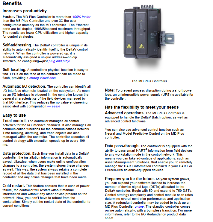
The DeltaV M series MD Plus controller is an industrial control core equipment launched by Emerson Process Management, mainly responsible for communication and control tasks between field devices and other nodes in the control network. It is compatible with the control strategies and system configurations created by early DeltaV systems. On the basis of having all the functions of the M5 Plus controller, it has increased memory capacity to meet the needs of large-scale batch processing and other memory intensive applications. At the same time, it needs to be installed quickly in conjunction with the DeltaV I/O subsystem. The specific execution method of its control language can refer to the product data sheet in the Configuration Software Suite.

Core advantages

(1) Enhance productivity

High performance operation: The computing speed is over 400% faster than the M5 Plus controller, and the user configurable memory is more than three times that of the MD controller; The Ethernet port supports full duplex mode, with a maximum throughput of 100MB/s, which can effectively reduce CPU utilization and improve control strategy processing capability.

Convenient automatic function

Automatic addressing: After connecting to the DeltaV control network, a unique address can be automatically assigned upon power on, without the need for DIP switches or additional configurations, achieving plug and play functionality.

Automatic positioning: The LED lights on the controller panel can flash through operation to visually indicate its physical location, making it easy to locate.

Automatic I/O detection: It can identify all I/O interface channels on the I/O subsystem. After the I/O interface is inserted, it can immediately obtain the basic characteristics of the field devices managed by the interface, reducing useless configuration work.

(2) Strong usability

Comprehensive control capability: not only managing all control activities of I/O interface channels, but also responsible for all communication functions of the communication network, while managing timestamps, alarms, and trend objects. The control strategy execution speed can reach up to once every 100 milliseconds.

Data protection mechanism: When installing data into the controller, relevant installation information will be automatically saved; When users modify the controller configuration online, the system will also store these changes and fully record all data and online modification traces in the controller.

Cold start function: Restarting after power failure does not require manual intervention or assistance from other devices in the network. Simply set the controller restart status to the current working condition to avoid the tedious operation of restarting from the workstation; In addition, it can also be paired with an uninterruptible power supply (UPS) to prevent short-term power outages from interfering with the process.

(3) High flexibility, adaptable to diverse needs

Support advanced operations: compatible with DeltaV Batch options, and can also run advanced control functions such as neural network control and model predictive control.

Data transmission capability: capable of transmitting intelligent HART information from field devices to any workstation node in the control network, supporting applications such as Asset Management Solutions, and achieving remote management of HART information in HART or Foundation fieldbus devices.

System Scalability: As the system size expands, the number of Device Signal Tags (DST) allocated to the controller can be increased by upgrading software licenses, from an initial 50 to 750 (the overall performance and application scale of the controller are affected by the complexity of the control strategy and the scanning rate of the control module); Redundant controllers can also be added online as backups for MD Plus controllers, and the backup controller can automatically switch online without disturbance during the transition process (refer to the “I/O Redundancy” product data sheet for details).

Compatible with legacy system migration: Provides DeltaV platform support for PROVOX and RS3 controller migration, adapting to corresponding migration I/O interfaces. Among them, when migrating the PROVOX system, the original I/O can be retained through the migration I/O interface, supporting up to 750 actual I/O signals. The serial dataset is migrated to the DeltaV serial card, and because the DeltaV system supports direct module reference, there is no need to use virtual I/O anymore; RS3 system migration can also be fully supported through MD Plus controllers and corresponding migration I/O interfaces.

Installation and environmental requirements

(1) Installation related

Installation method: Adopting a modular plug and play structure, system expansion can be achieved on the basis of a single controller. It is installed in the right slot of the 2-wide Power/Controller Carrier and supports installation in Class 1, Div 2 or ATEX Zone II hazardous environments (specific installation details need to refer to “Zone 2 installation instructions (12P2046)” and “Class 1 Division 2 installation instructions (12P1293)”).

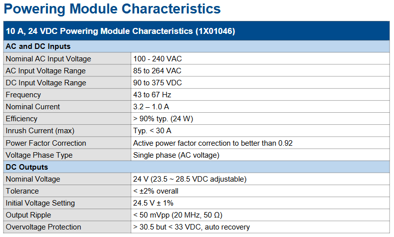
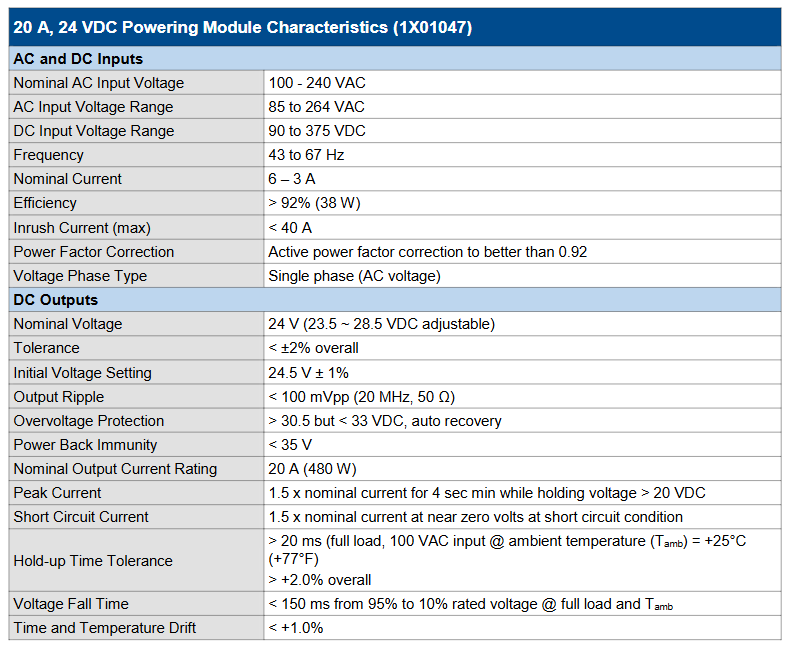
Supporting requirements: A dedicated installation carrier must be selected for each controller (refer to the “I/O Carrier” product data sheet for details), and each controller must be equipped with an independent system power supply (refer to the “Power Supplies” product data sheet for details).

(2) Environmental parameters

Specific requirements for environmental indicators

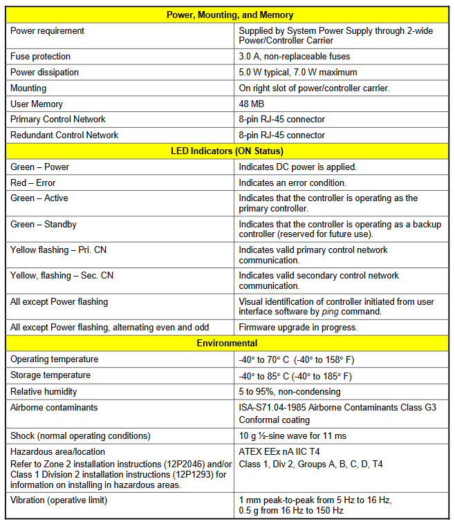
Working temperature -40 ° C~70 ° C (-40 ° F~158 ° F)

Storage temperature -40 ° C~85 ° C (-40 ° F~185 ° F)

Relative humidity 5%~95% (no condensation)

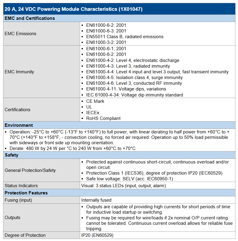
The air pollutants meet the ISA-S71.04-1985 G3 level air pollutant standard and have a conformal coating

Shock (normal working state) 10g half sine wave, lasting for 11 milliseconds

Hazardous area/location level ATEX EEx nA IIC T4, Class 1, Div 2, Groups A, B, C, D, T4 level

When the vibration (working limit) is between 5Hz and 16Hz, the peak to peak value is 1mm; 0.5g at 16Hz~150Hz

Technical specifications

Specific content of technical parameters

The power requirement is supplied by the system power supply through a 2-wide Power/Controller Carrier

Fuse protection 3.0A non replaceable fuse

Typical power consumption is 5.0W, maximum value is 7.0W

User memory 48MB

Main control network interface 8-pin RJ-45 connector

Redundant control network interface 8-pin RJ-45 connector

LED indicator light (meaning lit) – green (power): indicates that the DC power supply has been connected

-Red (Error): Indicates the existence of an error status

-Green (Active): indicates that the controller is running as the main controller

-Green (Standby): indicates that the controller is running as a backup controller (reserved function, not yet enabled)

-Yellow flashing (Pri. CN): indicates normal communication in the main control network

-Yellow flashing (Sec. CN): indicates that the backup control network communication is normal

-All flashing except for the power light: triggered by the ping command of the user interface software, used for visual recognition of the controller

-Except for the power light, even and odd digits flash alternately: indicating that a firmware upgrade is in progress

Emerson Ovation ™ Power system (5X00785G09)

Basic Overview

Ovation ™ The power system is a DIN rail mounted power supply developed by Emerson, which integrates four modular fanless power supply systems designed for Ovation ™ The controller and I/O module provide reliable and stable power supply. The system adopts redundant configuration, with each configuration having independent external wide range AC or DC input power supply. It supplies power to each controller chassis and related I/O modules through dual diode bus 24 VDC output, and supports wetting power supply for circuit and I/O module contacts. If necessary, it can also provide 48 VDC auxiliary power supply.

The system provides two independent output schemes, namely “24 VDC/10 A/240 W main power supply+24 VDC/10 A/240 W auxiliary power supply” and “24 VDC/20 A/480 W main power supply+24 VDC/20 A/480 W auxiliary power supply”, which can be flexibly selected according to actual power requirements.

Core Features

Redundancy and reliability design: Adopting redundant power supply configuration, the main power supply and auxiliary power supply are independently separated in the main and backup configurations; By using diode combiner power supply, the power supply is ensured to be continuously available, avoiding single point failures that may cause system power outages.

Wide range input capability: Supports dual input (AC and DC), with AC input voltage range of 85-264 VAC (frequency 43-67 Hz) and DC input voltage range of 90-375 VDC, suitable for power supply needs in different scenarios while reducing spare parts inventory.

High efficiency and low loss: The power efficiency is high (typical efficiency of 10A module>90%, efficiency of 20A module>92%), and it has active power factor correction function. The power factor can be optimized to 0.92 or above, reducing power consumption; Fanless modular design reduces the risk of heat dissipation failures and extends the service life of equipment.

Convenient maintenance and installation: The power supply supports hot swapping and can be replaced online, reducing downtime; Adopting a backplane design with pre installed DIN rails, it facilitates the installation of power distribution modules, circuit breakers, and power modules, enabling rapid deployment and reducing production losses.

Comprehensive monitoring and protection: equipped with continuous system monitoring function, visually displaying the operating status through three status LEDs (input, output, alarm); Provide multiple protections such as overvoltage, short circuit, overload, and open circuit, in compliance with IP20 protection level (IEC60529) and Class 1 protection level (IEC536), to ensure equipment safety.

Details of two power schemes

(1) 10A power scheme (output 240W)

Composition structure: Includes redundant power supply configurations (primary and backup), each with independent 10A main and auxiliary power supplies; Equipped with a power distribution module to distribute the diode bus output to the controller and I/O bus; The overall installation is on a backplane with pre installed DIN rails, which also needs to be connected to a power distribution module, circuit breaker, and four 10A power modules.

Service life: The expected service life of a 10A power module is 8 years at an ambient temperature of 40 ° C.

Core parameters (1X01046 module)

Input characteristics: Rated AC input voltage 100-240 VAC, rated current 3.2-1.0 A, typical maximum surge current<30 A, supports single-phase AC voltage.

Output characteristics: Rated output voltage of 24 VDC (adjustable range 23.5-28.5 VDC), initial voltage setting of 24.5 V ± 1%, total tolerance<± 2%; Output ripple<50 mVpp (20 MHz, 50 Ω); Overvoltage protection threshold of 30.5-33 VDC, supporting automatic recovery; The rated output current is 10 A, the peak current is 1.5 times the rated current (for 4 seconds, with voltage maintained>20 VDC), and the short-circuit current is 1.5 times the rated current (near zero voltage state).

Environment and stability: Operating temperature -25 ° C to+60 ° C (full power operation), linear derating from 60 ° C to 70 ° C (power decreases by 12 W for every 1 ° C increase, to 120 W); Storage temperature -40 ° C to+85 ° C; voltage holding time>20 ms (full load, 100 VAC input, 25 ° C environment), voltage drop time<150 ms (from 95% rated voltage to 10% at full load), time and temperature drift<1.0%.

Certification and anti-interference: Compliant with EN61000 series EMC anti-interference standards (such as ESD Level 4, Radiation Immunity Level 3, etc.), certified by CE, UL, IECEx, and compliant with RoHS standards.

(2) 20A power scheme (output 480W)

Composition structure: also adopts redundant power supply configuration (primary and backup), including independent 20A main power supply and auxiliary power supply; Equipped with combiner diodes to ensure continuous power supply, as well as power distribution terminal blocks; Installed on a backplane with pre installed DIN rails, the backplane needs to be connected to power distribution terminal blocks, combiner diodes, circuit breakers, and four 20A power modules.

Service life: Under an ambient temperature of 40 ° C and a 10A load, the expected service life of a 20A power module is 15 years, which is more durable than the 10A solution.

Core parameters (1X01047 module)

Input characteristics: Consistent with the input range of 10A module (85-264 VAC/90-375 VDC), rated current of 6-3 A, maximum surge current<40 A, also supports active power factor correction (>0.92) and single-phase AC input.

Output characteristics: Rated output voltage of 24 VDC (adjustable range 23.5-28.5 VDC), initial voltage setting and total tolerance consistent with the 10A module; Output ripple<100 mVpp (20 MHz, 50 Ω); The rated output current is 20 A, and the peak current and short-circuit current characteristics are the same as those of the 10A module (1.5 times the rated current); The overvoltage protection threshold is also 30.5-33 VDC (automatic recovery).

Environment and stability: The working temperature range and derating rules are consistent with the 10A module (power decreases by 24 W for every 1 ° C increase from 60 ° C to 70 ° C, and then decreases to 240 W); The voltage holding time, drop time, and drift parameters are the same as those of the 10A module to ensure output stability.

Certification and anti-interference: EMC anti-interference standards, safety certifications (CE, UL, IECEx), and RoHS compliance are consistent with 10A modules, and additionally comply with EN55011 Class B radiation emission standards for better electromagnetic compatibility.

Safety and Protection

Universal protection: All modules have continuous short circuit, continuous overload, and open circuit protection; The input side is equipped with a built-in fuse, and the output side can choose whether to additionally fuse according to the load requirements (if unable to withstand twice the rated output current); Compliant with the Safety Low Voltage (SELV) standard according to IEC60950-1, reducing the risk of electric shock.

Physical protection: Adopting a fully enclosed metal shell, equipped with fine ventilation grilles to block small components from entering, with a protection level of IP20 (EN60529), suitable for industrial site environments.

Emerson DeltaV Intelligent Switch

Basic Overview

DeltaV intelligent switch is a product in the next generation control system that uses commercial off the shelf (COTS) components, known as “dedicated commercial components”. It combines the low cost of commercial off the shelf components with DeltaV specific software and features, providing stronger integration and plug and play capabilities in control networks. This switch can run in a DeltaV network without configuration, and advanced features can be easily configured through the DeltaV wizard. It also has an advanced security feature of automatic port locking, which can adapt to today’s complex network environment.

Product advantages

Plug and play installation: The switch is pre configured with settings compatible with DeltaV, and can be installed into the DeltaV network right out of the box. It fully supports DeltaV network communication without user configuration, and users cannot change the default configuration to avoid configuration errors.

Automatic locking function: It can prevent unauthorized network connections, and the one click locking function can automatically lock all unused network ports in the system, in compliance with factory security policies. Only users with specific permissions can perform locking and unlocking operations, and all locking and unlocking events will be recorded in the DeltaV event log for easy monitoring.

Rich hardware configuration: Provides a variety of hardware solutions, from 24 port rack mounted units to fixed port and modular on-site installed switches, to meet various network needs and replace currently supported Cisco and Hirschmann switches. In most cases, it can be used as a direct replacement for existing managed switches.

Comprehensive support service: As an Emerson product, it is fully supported by Emerson, including technical support, warranty support, product support, and training from global service centers. The intelligent switch is included in the fast module replacement plan, which can quickly replace faulty equipment.

Product model and specifications

VE6046, VE6047, and VE6048 are 19 inch rack mounted modular switches with 8, 16, or 24 ports, respectively, featuring wired and fiber optic connections, as well as 2 Gigabit wired or fiber optic uplinks.

VE6041: DIN rail style 8-port 10/100 MB switch with fiber optic and wired uplink, available in standard and extended temperature/compliant coating versions.

VE6042 and VE6043 are modular switches installed on DIN rails, supporting 8, 16, or 24 ports (using wired and fiber optic communication modules). In addition to 24 local ports, VE6043 also provides 2 Gigabit wired or fiber optic uplink ports, with standard and extended temperature/informational coating versions.

Network monitoring and settings

Network monitoring: Provides read-only access to switch network monitoring functionality, which can be collected using third-party SNMP applications (such as “What’s Up Gold”) and standard SNMP v3 communication to monitor switch health status, or accessed through the switch’s built-in web interface.

Switch settings: Easily set up through the built-in DeltaV wizard, connect serial cables and run terminal access applications to enable advanced features in a simple Q&A format. The wizard restricts address selection and only allows pre configured addresses and subnet addresses within the DeltaV LAN for easy setup.

Security and compatibility

Access security: All user access to the switch is password protected and can be changed through the DeltaV wizard to allow remote access for read-only user functionality and through the network access settings wizard. Remote access can also be disabled, and SNMP v3 access is always in read-only mode.

Compatibility: Compatible with all versions of the DeltaV system, can be used to expand or retrofit existing DeltaV systems, can also serve as a backup for some existing Cisco and Hirschmann switches (automatic switch locking is only compatible with DeltaV v10.3), and can be installed and used in hybrid systems with currently supported Cisco or Hirschmann switches.

Hardware Reliability and Network Examples

Hardware reliability: Based on hardware from well-known industrial grade network equipment suppliers, all switches have no fans, redundant power connections and external alarm contacts, as well as high temperature and conformal coating versions, suitable for harsh environments.

Network example: In a typical network implementation, VE6048 can be used as a central switch located in a rack room with AC power supply, while VE6041 (or VE6042, VE6043) is used as an on-site installed switch for the controller at the installation location. When necessary, multiple VE6048 switches can be interconnected through gigabit ports to provide network backbone for connecting devices or other DeltaV switches. VE6042 or VE6043 can also be used as a central switch according to demand.

Ordering Information and Specifications

General specifications: Different models of switches have specific regulations on environmental conditions (working temperature, storage/transportation temperature, relative humidity, etc.), user access methods, diagnostic functions, setting requirements, security features, redundancy, real-time performance, and other aspects.

Detailed specifications for each model: VE6041, VE6042, VE6043, VE6046, VE6047, VE6048 and other models have specific parameters in terms of port quantity, type, power requirements, mechanical structure, EMC anti-interference, etc.

Media module and transceiver: The VE6045 media module can be used for VE6042 and VE6043 switches, with multiple types available; There are also 100Mb and 1Gb SFP transceivers, suitable for specific ports of different models of switches.

Accessories: including rack installation kit, terminal access cable, etc. The terminal access cable needs to be ordered separately, and one cable can be compatible with all switch models.

Certification and Support

Certification: The switch has obtained multiple institutional certifications and declarations, such as CE declaration, FCC declaration, cUL certification, etc. Different models have slight differences in certification.

Support and Contact: Sales offices can be contacted through the website or phone. For large-scale power, water, and wastewater applications, relevant departments can be contacted. All sales are subject to Emerson’s terms and conditions, and Emerson reserves the right to modify or improve product design or specifications at any time without prior notice.

Emerson A6110 Dual Channel Shaft Vibration Monitor

Basic Overview

The A6110 dual channel shaft vibration monitor is a module of the A6000 machine monitoring system, controlled by a microprocessor and used in conjunction with two eddy current measurement chains to measure and monitor the relative shaft vibration of various turbines, compressors, fans, gearboxes, and other equipment. Its two channels can be configured to be used as independent channels or interrelated, with multiple operating modes, and characteristic values can be output through the 0/4… 20mA current of each channel.

CSA certification related

Certification Mark: In order for CSA certification to be valid, all devices (IMR 6000/xx and A6000 modules) must be labeled with the corresponding CSA label. Without a label, they will not be certified by CSA.

Acceptance criteria: 24V safe low voltage SELV LPS (C22.2 60950-1) power supply is required, and the voltage comes from an independent power source; The IMR system should be placed in a suitable fire-resistant enclosure; The working environment temperature is between 0 ° C and 45 ° C, and sufficient ventilation space should be provided. If the rack environment temperature exceeds 45 ° C, cooling measures should be taken; When stacking multiple IMR units, a cooling fan bracket needs to be installed in the middle.

Installation related

Installation requirements: According to the IEC 61010 directive, fixed installation systems must be equipped with a power disconnect device, which should be easy for users to operate and labeled.

Installation and assembly: It needs to be installed in a 3U slot or other Intermas compatible housing in a 19 inch rack, and the slot should be equipped with a 48 pin plug connector (DIN 41612, design F 48 M). Before installation, check the slot wiring, push the monitor into the slot and gently press in the plug connector, then tighten the two fixing screws on the front panel.

Jumper setting: The operation of the RS 485 bus requires the installation of electrical terminators on the first and last bus devices, which are achieved through plug-in jumpers on the controller board; The raw signal of the sensor can be switched to the corresponding terminal of the connecting strip through J2 jumper, and the controller board needs to be removed when switching.

Technical parameters

signal conditioning

Two independent signal inputs, with differential voltage amplification input, resistant to open and short circuits.

Sensor signal output, dynamic output, and scaled DC output each have their own nominal range, measurement range, accuracy, frequency range, and other parameters.

The characteristic values form a dependency configuration, with multiple operating modes and corresponding parameters for current output and signal output.

Channel monitoring: continuously monitors sensor signals, system voltage, microprocessor functions, etc. The channel status has three types: normal, error, and release delay. It is displayed through the green LED on the front panel, and also has channel clearing output and external disabled input.

Limit formation and alarm: There are two alarm channels, each with an alarm output ALERT and DANGER, which can be individually set with limit values. There are alarm delay and alarm blocking functions, and the alarm status is displayed through a red LED. The alarm output is the collector/emitter segment isolated by optocouplers.

Communication interface: includes RS 232 interface (for connecting laptops/computers for configuration and visualization) and RS 485 interface (for communicating with MMS 68xx epro analysis and diagnostic system and configuration software).

Power supply: Two redundant diodes decoupled input, nominal+24V, with allowable voltage range and power consumption requirements. The sensor power supply is separated from the power supply voltage, and has corresponding parameters such as voltage, ripple, and current.

Environmental conditions: There are clear regulations on application category, environmental temperature, storage and transportation temperature, working altitude, vibration, impact, shell protection level, electromagnetic compatibility, allowable pollution level, and usage environment.

Mechanical structure: The PCB is in European standard format, with specific parameters for width, plug connectors, front panel components (LED, SMB socket connectors, mini DIN circular socket connectors), and weight.

Other information

Repair and maintenance: No maintenance is required during operation, and repair or calibration can only be carried out by Emerson. For repairs, relevant guidelines must be followed, RMA numbers must be obtained, and necessary information must be provided.

Version revision: A PI revision list is provided, which records the dates, changes, and chapters of different versions.

CE Conformity Declaration: Declare that the product complies with relevant EU directives and standards. Modifying the product without explicit permission will result in the invalidation of conformity and operating permits. Non professionals should check the conditions and requirements of the usage area before putting it into operation.

Emerson MMS 3210 Dual Channel Axial Displacement Transmitter

​Basic Overview

The MMS 3210/… dual channel shaft displacement transmitter is part of the improved MMS 3000 transmitter system, used for monitoring and protecting various types of turbomachinery. The new generation transmitter has highly flexible hardware options and diverse combination possibilities, which can be best adapted according to the needs of the corresponding factory. It can economically measure and monitor relative axis displacement and axis position through eddy current sensors.

Application Fields

Suitable for various types of turbomachinery, fans, compressors, gearboxes, pumps, and similar rotating machinery. Due to its bus capability, it is suitable for both large systems with programmable logic control and host computers used in power plants, refineries, and chemical plants, as well as small factories with only a few measurement points and decentralized data processing.

Function and Design

Can convert the input signal of the eddy current sensor into two independent signals proportional to the shaft displacement or relative expansion.

The integrated module and sensor monitoring can detect the fault function of sensors and module electronic devices. At this time, the normal output (channel clearing) status will change, and the 4-20 mA current output indicates 0 mA.

All necessary configurations are completed through MMS 3910W configuration software, and the transmitter is delivered with standard configurations suitable for most applications, or other configurations can be prepared at the factory.

Technical parameters

Sensor Input: Two independent inputs, suitable for series eddy current sensors such as PR 6422/… and PR 6423/…, with standard internal “Lemo” connectors and optional internal “Lemo” connectors with extended measurement range and external “Harting” connectors.

Measurement range: can be freely selected by configuring software according to the applied sensor.

Frequency range: The low-pass filter is 10Hz.

output characteristic

The standard consists of two current outputs proportional to the selected characteristics and related to system grounding, which can be freely allocated to the measurement channel; Choose between two galvanic separated current outputs proportional to the selected characteristics, or no current output.

The current output range is 0/4… 20 mA or 20… 4/0 mA, with a maximum load of 500 ohms and open circuit and short circuit protection.

Buffer sensor signal: Two signal outputs for analysis and diagnosis, one for each channel, proportional to the dynamic sensor signal, accessible through terminals, unfiltered voltage output of 2-10 V, with an error of ± 2.5%.

Limit and channel monitoring: A total of 5 functional outputs are provided, with limit values programmable for individual or combined measurements. Function outputs can be freely allocated through configuration software and have multiple output options.

Data interface: The standard is RS 232 interface, with optional RS485 bus (with epro protocol V2.0) and PROFIBUS DP.

Linear error: 0.25% at 25 ° C without sensors; When there are sensors, different models of sensors have different errors within the standard measurement range. The error for expanding the measurement range can be found in the data table.

Output temperature stability:<0.08%/10K.

Long term drift: up to 1% of full scale.

Power supply: Optional redundant power supply, decoupled through diodes, nominal+24 V DC, allowed voltage range+18…+31.2 V DC, power consumption depends on built-in options, maximum 6 W.

Shell: made of aluminum, corrosion-resistant, with a protection level of IP 65 (compliant with DIN 40050, IEC 144, CE certification), passed EMC testing according to EN 55011 and EN 61326.

Environmental conditions: The maximum allowable temperature of the installation surface and the working temperature range may vary depending on the installation method. The allowable relative humidity is 0… 95% (without condensation), and there are corresponding standards for vibration and impact.

Installation direction: It is best to have the cable gland facing downwards.

Weight: Depending on the selected hardware option, the maximum net weight is 1.3 kg and the maximum gross weight is 1.5 kg.

Module and sensor monitoring

Internal module monitoring continuously checks whether the input signal is within the predefined range, whether the cable between the transmitter and sensor is normal (no short circuit/disconnection), system voltage, etc. The status monitored by modules and sensors can be signaled through the switch contacts of functional outputs.

Main configuration parameters

Configure through MMS 3910W configuration software, which needs to be ordered separately. There are many adjustable parameters that vary depending on the selected operating mode and measurement function, including KKS identification, operating mode, sensor sensitivity, etc. for each channel.

Limit monitoring and functional output

There are five functional outputs, each of which can be assigned to limit values and channel clearing functions. The allocation between input channels and functional outputs can be freely selected. The output of channel clearing can be performed separately for each channel, or a combination of logical “OR” or “AND” can be used. The limit can be set for the sum of a single channel and a combination of two channels, and there are multiple alarm functions to choose from.

Size

Partial dimensional data is provided in millimeters. If the external converter option is selected, the housing comes with a Harting plug on the side, and dimensions can refer to the MMS 3120 data sheet. The M20/PG13.5 adapter is included with the delivery.

Operation mode

Provide different measurement modes, which can be configured through MMS 3910W configuration software. In the operating mode of a single or dual channel transmitter without combining channel results, the relative position corresponding to the sensor used can be measured; In the dual channel mode of combining channel results, multiple measurement modes can be achieved.

Input/Output

Includes standard RS 232 interface, redundant 2 x+24 V power supply voltage, optional binary output, current output, and corresponding pin allocation and LED allocation.

Ordering Options

The sensor inputs K1 and K2 are two identical input channels and cannot be used interchangeably. There are multiple options for communication methods, output characteristics, functional outputs, displays, converters, etc. Standard models and accessories available for immediate supply were also provided.

Emerson MMS 3120 Dual Channel Bearing Vibration Transmitter

Equipment Overview

The MMS 3120/xxx-xxx dual channel bearing vibration transmitter is part of the improved MMS 3000 transmitter system, used for monitoring and protecting various types of turbomachinery. This transmitter has highly flexible hardware options and multiple combination possibilities, which can best adapt to the needs of the corresponding factory. It achieves economic measurement and monitoring of absolute bearing vibration through the use of seismic absolute vibration sensors, and complies with VDI 2056/.. And API 670 standards.

Application scenarios

Suitable for various types of turbomachinery, fans, compressors, gearboxes, pumps, and similar rotating machinery. Due to its bus capability, it is suitable for both large systems equipped with programmable logic controllers and hosts (such as power plants, refineries, and chemical plants) and small factories with few measurement points and scattered data processing. Can be used in conjunction with all EPR absolute bearing vibration sensors, such as PR 9268/20, PR 9268/30, PR 9268/60, and PR 9268/70.

Function and Design

Signal conversion: Convert the signal of a vibration sensor into two independent signals proportional to the vibration velocity or amplitude (peak to peak), or output signals proportional to the maximum value of these characteristic values.

Monitoring function: Integrated module and sensor monitoring function, capable of detecting faults in sensors and module electronic devices. In the event of an error, the status of the “OK” output will change, and the 4-20 mA current output will indicate 0 mA.

Configuration method: All necessary configurations are completed through MMS 3910W configuration software. The transmitter comes with standard configurations suitable for most applications at the factory, or other configurations can be made at the factory according to requirements.

Technical parameters

Sensor Input

Two independent inputs for PR 9268/20, PR 9268/30, PR 9268/60, and PR 9268/70 seismic vibration sensors.

Sensor connection: Harting connector.

Measurement range: It can be freely selected through configuration software based on the measurement range of the applied sensor.

Frequency range (-3dB): High pass filter 5/10/15 Hz; low-pass filter 50… 1500 Hz.

output

Current output: The standard is two current outputs, proportional to the selected characteristics and related to system grounding, which can be freely allocated to the measurement channel; Choose between two electrically isolated current outputs or no current output. The output range is 0/4… 20 mA or 20… 4/0 mA, with a maximum load of 500 ohms and open and short circuit protection.

Buffer sensor signal: Two signal outputs for analysis and diagnosis, one for each channel, proportional to the dynamic sensor signal, accessed through terminals, unfiltered voltage output of ± 5.0 V, with an error of ± 2.5%.

Function output: A total of 5 function outputs are provided, which can be freely allocated through configuration software to indicate limit values or clear channel status, etc. There are multiple options, such as no function output, 5 optocoupler outputs, 5 relay contacts (normally open contacts), 5 photoelectric MOS relays, etc.

Data interface: The standard is RS 232 interface, used for transmitter configuration and measurement data display; Optional RS485 bus (with epro protocol V2.0) and PROFIBUS DP.

Accuracy and stability

Linear error (without sensor): 0.2% at 25 ° C.

Linear error (with sensor):<2.2% at 25 ° C.

Output temperature stability:<0.08%/10K.

Long term drift: up to 1% of full scale.

Power supply: Optional redundant power supply, with diode decoupled LED, nominal voltage+24 V DC, voltage range+18…+31.2 V DC, power consumption depends on built-in options, maximum 6 W.

Shell and Protection

Shell: Aluminum, non corrosive.

Protection level: IP 65 (compliant with DIN 40050, IEC 144), CE certification, EMC testing in accordance with EN 55011 and EN 61326.

Environmental conditions (compliant with IEC 359, DIN 43745)

The maximum allowable temperature for installation surface is 65 ° C (90 ° C when installed on bolts with a spacing of 10mm).

Working temperature range: -20…+65 ° C (-20…+45 ° C when installed on 10 mm spaced bolts).

Allowable relative humidity: 0… 95%, no condensation.

Vibration and impact: impact 20 g/2 ms; Vibration at 5 g/60 Hz.

Installation and Dimensions: The preferred installation direction is downwards with the cable gland. Please refer to the drawing for the dimensions. The maximum net weight is 1.3 kg and the maximum gross weight is 1.5 kg.

Module and sensor monitoring

Internal module monitoring continuously checks the following functions: whether the input signal is within the predefined range; Is the cable between the transmitter and sensor normal (no short circuit/broken wire); System voltage. The monitoring status of modules and sensors can be signaled through the switch contacts of functional outputs.

Configure parameters and operating modes

Main configuration parameters: configured through MMS 3910W configuration software, adjustable parameters include KKS identification for each channel, operating mode, sensor sensitivity, series resistance of safety barriers, measurement range, etc. (may vary depending on the selected operating mode and measurement function).

Operation mode: Provides multiple measurement modes, which can be configured through MMS 3910W configuration software. In single channel and dual channel modes, the selectable measurement modes include vibration amplitude (SO-P, SP-P, MAX (x, y)) and vibration velocity (VRMS, MAX (x, y)).

Ordering options and standard models

Ordering Options

Communication: RS 232, RS 485, PROFIBUS DP.

Sensor inputs K1 and K2: two identical input channels that cannot be mixed, corresponding to PR 9268/.

Output characteristics: None; 2 with system reference (standard); Two electrical isolations.

Function output: None; 5 optocouplers (standard); 5 relay contacts (normally open contacts); 5 photoelectric MOS.

Display: None (standard); Equipped with an 8-bit display.

Standard Model

MMS 3120/010-000: Sensor PR 9268/.., RS 232, no bus communication, current output with common ground, no functional output, no display, order number 9100-03025.

MMS 3120/011-000: Sensor PR 9268/.., RS 232, no bus communication, current output with common ground, functional output, no display, order number 9100-03026.

Emerson MMS 677X Dual Channel Bar Chart Indicator

Equipment Overview

The MMS 677X series dual channel bar chart indicator (including MMS 6771 and MMS 6772) belongs to the MMS 6000 series machine monitoring system and is used to display the measurement results of the MMS 6000 module. With a dual channel design, the MMS 6000 monitor can display data from two channels simultaneously. The bar chart resolution is 100 scale lines, corresponding to a range of 0… 100% or ± 50%, and can present measurement results at a resolution of 1%. It adopts a 19 inch design.

Technical parameters

power supply

Power supply method: Redundant power supply is achieved through two power inputs, which are separated by diodes. At least one power input is required to power the module.

Input voltage: 10…+24… 26 V DC.

Power consumption:<1 W.

signal input

Each indicator channel has one voltage input.

Input voltage: 0… 10 V.

Input impedance:>1 M Ω.

bar chart

Display type: Green segment display, with red segments every 10%.

Accuracy: ± 0.5% ± 1 segment of full scale.

Resolution: 101 segments.

Bar height: 75mm.

Bar chart width: 4.2 mm.

Environment and Protection

Protection level: The module complies with the IP 00 standard of DIN 40050; The front panel complies with the IP21 standard of DIN 40050.

Climate conditions: Complies with DIN 40040 KTF grade.

Working temperature range: 0…+65 ° C.

Storage and transportation temperature range: -30….+85 ° C.

Allowable relative humidity: 5… 95%, no condensation.

Allowable vibration: in accordance with IEC 68-2 Part 6, vibration amplitude within the range of 10… 55 Hz is 0.15 mm; vibration acceleration within the range of 55… 150 Hz is 16.6 m/s ².

Allowable impact: Complies with IEC 68-2 Part 29, with a peak acceleration of 98 m/s ² and a nominal impact duration of 16 ms.

Size and weight

Size: Using PCB/European standard card format that complies with DIN 41494 standard (100 x 160 mm); Width 20.0 mm (4 TE); Height 128.4 mm (3 HE); Length 160.0 mm.

Weight: Net weight approximately 320 g; Gross weight (including standard export packaging) approximately 450 g; Packaging volume approximately 2.5 dm ³.

Space requirement: Each 19 “rack can accommodate 14 modules (28 channels).

Order Information

MMS 6771 Bar Chart Indicator (0… 100%): Order Number 9100-00067.

MMS 6772 Bar Chart Indicator (± 50%): Order Number 9100-00075.

Emerson Martens Standard Signal Instrument S 1010

Equipment Overview

Martens Standard Signal Instrument S 1010 is designed to measure industrial standard signals of 0/4… 20mA or 0… 10VDC. It has a built-in transmitter power supply and can be directly connected to 2-wire and 3-wire transmitters (such as those used for pressure or temperature measurement). Its indication range and decimal point can be freely programmed within the range of ± 9999 (0) digits, suitable for signal measurement and monitoring in industrial sites.

Main characteristics

Display function: Equipped with a 14.2mm red LED display screen, the indication range is ± 9999 (0) digits, and the indication range and decimal point can be freely programmed.

Alarm output: Up to 2 alarm outputs, the switch performance of the alarm output can be programmed to the minimum or maximum function.

Analog output: It can generate analog output signals proportional to the input signal, including 0… 20mA/0… 10V DC, 4… 20mA/2… 10V DC. The output will automatically switch from current signal to voltage signal according to the load.

Shell and Protection: The on-site shell with snap on cover is used, equipped with 2 M16x1.5 cable glands (other specifications can refer to option 09 or customized as needed), and the protection level is IP65.

Other functions: Parameters can be programmed through the front film keyboard; Equipped with digital filtering function, it will continuously average the last 16 measurement values and display the results on the screen after activation.

Technical parameters

power supply

Power supply voltage: 230V AC ± 10%, 115V AC ± 10%, 24V AC ± 10%, or 24V DC ± 15%.

Power consumption: maximum 3.5VA, 5VA with analog output.

Working temperature: -20…+55 ° C (standard), with an extended temperature range available upon request.

Rated voltage: 250V (according to VDE 0110, between input/output/supply voltage), overvoltage category III.

Test voltage: 4kV between input/output/supply voltage.

Electromagnetic compatibility: Complies with EN55022, EN60555, IEC1000-3/4/5/11/13 standards.

input

Current input: 0/4… 20mA, Ri=10 Ω.

Voltage input: 0… 10V, Ri>100k Ω.

Accuracy:<0.1% ± 2 digits.

Temperature coefficient: 0.004%/K.

Transmitter power supply: U ₀ about 24V, Ri about 150 Ω, maximum 50mA (25mA with relay and analog output).

display

Display screen: red LED, 14.2mm.

Display range: ± 9999 (0), with leading zero suppression.

Parameter display: 2 red LEDs, 7mm (parameter and output indicator).

output

Relay: SPDT, 250V AC<250VA<2A, 300V DC<50W<2A.

Analog output: 0/4… 20mA (load ≤ 500 Ω), 0/2… 10V (load>500 Ω), not isolated from input, automatically switches output types according to load.

Accuracy: 0.1%; Temperature coefficient 0.01%/K.

other

Shell: Made of polyamide material, containing glass fiber PA6-GF15/15, keyboard made of polyester material.

Weight: Maximum 450g.

Electrical connection: Clamp terminal, 2mm ² single stranded wire, 1mm ² flexible wire, AWG14。

Protection: IP65 (enclosure), IP20 (terminals), compliant with German BGV A2 anti touch standard.

Operation and Configuration

Operation level: The device operation is divided into 2 levels. After the power is turned on, the device initializes and displays “Int”. After initialization, it enters the working level and can pre select the alarm output set point (if any). Press and hold the parameter button for more than 2 seconds to enter the configuration level of the program, where all parameters defining device functions can be programmed. If the configuration is completed or no button is pressed for more than 2 minutes, the program will return to the working level. Long press the parameter button for 2 seconds to exit the configuration level at any time.

error code

If the input signal exceeds the programmed measurement range by more than 3%, the A/D converter will be overloaded and the display screen will flash at a frequency of about 1Hz.

Error 1 “indicates an EEPROM test error. Pressing the parameter button will reload the EEPROM copy, and the device will operate according to factory settings. If the copy is invalid, the device needs to be sent to the factory for repair.

Loc “indicates program lock, refer to configuration page 7.

Parameter settings: The work level can display actual values, alarm output indicators, adjust display brightness, display maximum/minimum readings, set alarm output setpoints, etc; The configuration level can set parameters such as digital filtering, indication correction, input signal, fixed zero point, decimal point position, starting and ending values of indication range, alarm output set point, hysteresis, analog output, factory setting code, program lock, etc.

Order Code

The ordering code consists of multiple parts, representing input, alarm output, analog output, supply voltage, options, units, and additional text:

Input: 1 represents input standard signal 0/4… 20mA, 0… 10V DC, built-in transmitter power supply 24V DC maximum 50mA.

Alarm output: 00 indicates not installed, 2R indicates 2 alarm outputs (relays).

Analog output: 00 indicates not installed, AO indicates analog output 0/4. 20mA, 0/2… 10V DC (not isolated).

Supply voltage: 0 represents 230V 50/60Hz ± 10%, 1 represents 115V 50/60Hz ± 10%, 4 represents 24V 50/60Hz ± 10%, and 5 represents 24VDC ± 15%.

Options: 00 indicates no options, 01 indicates minimum and maximum value retention function, 07 indicates programmable display brightness, 08 indicates freely programmable analog output, 09 indicates 1 M20x1.5 multi-purpose (2x6mm), 1 M20x1.5.

Unit: appears in the unit field.

Additional Text: will be placed in the additional text field, with a maximum size of 3mm x 70mm (height x width).

image.png

Emerson CON021 Eddy Current Signal Converter

Basic Overview

CON021 is a vortex signal converter designed specifically for critical turbomachinery applications such as steam turbines, gas turbines, water turbines, compressors, pumps, and fans, used to measure radial and axial shaft displacement, position, eccentricity, and velocity/key phase.

Main performance parameters

dynamics

Frequency range (-3 dB): 0 to 20000 Hz.

Rise time:<15 µ s.

Applicable sensors: PR6422, PR6423, PR6424, PR6425, PR6426, PR 6453; PR6425 requires the use of an extended range converter, which can be CON021/91x xxx.

environmental parameters

Working temperature range: -30 to 100 ° C (-22 to 212 ° F).

Shock and vibration: 5g @ 60 Hz at 25 ° C (77 ° F).

Protection level: IP20.

Power supply and electrical parameters

Power supply voltage range: -23V to -32V when the output range is -4V to -20V; -21V to -32V when the output range is -2V to -18V.

physical parameters

Shell material: LMgSi 0.5 F22.

Weight: Approximately 120 grams (4.24 ounces).

Installation method: 4 M5x20 screws (included upon delivery).

Connection: The sensor adopts a self-locking Lemo plug; The power/output adopts screw terminal type (maximum 1.5mm ² wire).

Compliance and Certification

Compliant with CE 2014/30/EU, 2014/34/EU, 2011/65/EU, EN61326-1, DIN EN 50581 and other standards.

ATEX certification: EN 60079-0:2009, EN 60079-11:2012.

IEC Ex certification: IEC 60079-11:2011 (version 6.0), IEC 60079-0:2007-10 (version 5), IEC 60079-26:2006 (version 2).

CSA certification: CAN/CSA-C22.2 NO. 0-M91, CAN/CSA-C22.2 NO. 157-92 and other standards.

ANSI/UL standards: 913-2004, 1604-1995 UL 60079-15 2002、UL 61010-1。

Hazardous Area Certification

Inherent Safety (iA)

ATEX II 2 G Ex ia IIC T4 Gb, -20 ° C ≤ Ta ≤ 80 ° C (requires current limiting devices such as safety barriers).

IEC Ex ia IIC T4 Gb, -20 ° C ≤ Ta ≤ 80 ° C (requires current limiting devices such as safety barriers).

CSA Class I Zone 1, Groups A, B, C, D, T4, T4: -25 ° C ≤ Ta ≤ 80 ° C (requires current limiting devices such as safety barriers).

No spark (nA)

CSA Class I Zone 2, Groups A, B, C, and D.

Ex nA II T3.. T4 AEx nA II T3.. T4, T4: -25 ° C ≤ Ta ≤ 80 ° C.

Order Information

Different models correspond to different sensor types, measurement ranges, and linear errors, as follows:

Model Sensor Type Measurement Range Linear Error

CON021 PR6422, PR6423, PR6424, PR6426 1.0mm (standard range), 2.0mm (standard range), 4.0mm (standard range), 8.0mm (standard range) ≤ 1.5%, ≤ 1.0%, ≤ 1.5%, ≤ 1.5%

CON021/912-015 PR6422 1.5mm (extended range) ≤ 2.0%

CON021/913-030 PR6423 3.0mm (extended range) ≤ 1.5%

CON021/913-040 PR6423 4.0mm (extended range) ≤ 2.0%

CON021/914-060 PR6424 6.0mm (extended range) ≤ 1.0%

CON021/914-080 PR6424 8.0mm (extended range) ≤ 1.5%

CON021/914-100 PR6424 10.0mm (extended range) ≤ 2.0%

CON021/915-040 PR6425 4.0mm (standard range) ≤ 1.5%

CON021/915-060 PR6425 6.0mm (extended range) ≤ 2.0%

CON021/915-080 PR6425 8.0mm (extended range) ≤ 3.0%

CON021/915-100 PR6425 10.0mm (extended range) ≤ 4.0%

CON021/916-120 PR6426 12.0mm (extended range) ≤ 1.5%

CON021/916-160 PR6426 16.0mm (extended range) ≤ 2.0%

CON021/916-200 PR6426 20.0mm (extended range) ≤ 2.5%

CON021/916-240 PR6426 24.0mm (extended range) ≤ 3.5%

AMS 6500 Classic System Protection Card

System Overview

The AMS 6500 Classic system is a system developed by Emerson for the protection and condition monitoring of rotating machinery. It includes multiple protection cards and can achieve comprehensive monitoring and protection of key rotating machinery such as steam turbines, gas turbines, compressors, and water turbines. It complies with international standards such as API 670 and is PlantWeb ®  A part of the digital factory architecture that can be integrated with Ovation ®  And DeltaV ™  Process control system integration provides machinery health status information and diagnostic tools for operators and maintenance personnel.

Introduction to Main Protection Cards

A6740/A6740-10 16 channel output relay module

Purpose: To build a complete API 670 mechanical protection monitor in conjunction with AMS 6500, which can take clear, alarm, or danger signals from any channel as input and output them from output relays through Boolean logic and time delay.

Features: 3U size, 2-slot plug-in module, compliant with API 670 standard, hot swappable; A6740 is 12TE wide and suitable for IMR6000 series racks, while A6740-10 is 10TE wide and suitable for IMR6500 series racks; It has 60 inputs, 30 logical expressions, and 16 relay outputs.

Technical parameters: The relay is a redundant and configurable mechanical relay, with a control voltage of 13-32 VDC and a contact load of 48V, 1A. It can be selected as normally open/normally closed, normally powered on/off, and single pole double throw (SPDT); Logic supports multiple types and can define up to 30 logical expressions; Time delay of 0-30 seconds.

Environment and dimensions: working temperature of 0 ° -65 ° C, storage and transportation temperature of -40 ° -70 ° C, relative humidity of 5-95% (non condensing); A6740 is 60mm wide (12TE), A6740-10 is 54.46mm wide (10TE), 128.4mm high, and 160mm long.

A6125 shell piezoelectric vibration monitor

Purpose: Used to monitor the vibration of the casing from acceleration sensors, drive alarms and relays by comparing vibration parameters with alarm settings, and protect machinery.

Features: Dual channel, 3U size, 1-slot plug-in module, compliant with API 670 standard, hot swappable; Support remote selection of limit multiples and trip bypasses; There is buffering and proportional output before and after.

Technical parameters: Two independent differential inputs, input type is piezoelectric (accelerometer or speedometer), input resistance>100 k Ω, input voltage range -5 to+15 VDC; The frequency range varies depending on the type and configuration of the sensor; The sensor is powered by a constant current of 2-8mA and 30 VDC.

Environment and dimensions: working temperature 0 ° -65 ° C, storage temperature -30 ° -85 ° C, relative humidity 5-95% (non condensing); Width 30.0mm (6TE), height 128.4mm, length 160.0mm.

A6120 Shell Seismic Vibration Monitor

Purpose: Used in conjunction with electric seismic sensors to monitor the seismic vibration of the casing, and achieve mechanical protection by comparing vibration parameters with alarm settings.

Features: Dual channel, 3U size, 1-slot plug-in module, compliant with API 670 standard, hot swappable; Support remote selection of limit multiples and trip bypasses; There is buffering and proportional output before and after.

Technical parameters: Two independent channels, input type is electric (electromechanical), input resistance>100 k Ω, input voltage range -5-+15 VDC; Adjustable frequency range; Increase coil current by 0-8mA, configurable, with an accuracy of ± 0.5%.

Environment and size: Same as A6125.

A6824/A6824-R ModBus and Rack Interface Module

Purpose: Read the parameters of all AMS 6500 modules, output through ModBus TCP/IP and/or ModBus RTU (serial), and build a complete API 670 mechanical protection monitor.

Features: 3U size, 1-slot plug-in module, compliant with API 670 standard, hot swappable; Password protected user configuration; A6824 is 6TE wide with no redundancy options, while A6824-R is 4TE wide with optional redundancy.

Technical parameters: ModBus RTU (serial) baud rate 19.2 kbaud, data bit 8, parity bit, stop bit 1; ModBus Ethernet has RJ45 sockets and 10BaseT; Default IP address 192.168.255.1, subnet mask 255.255.255.0.

Environment and dimensions: working temperature 0 ° -65 ° C, storage temperature -30 ° -85 ° C, relative humidity 5-95% (non condensing); A6824 is 30mm wide (6TE), A6824-R is 25mm wide (4TE), 128.4mm high, and 160mm long.

Other protection cards

A6620 Process Input Monitor: Four channel, monitoring process inputs such as temperature, pressure, load, etc. The input type is voltage or current, with alarm output and multiple output modes.

A6140 Shaft Absolute Vibration Monitor: Dual channel, combined with relative displacement sensor and chassis mounted vibration sensor, monitors shaft absolute vibration.

A6220 axis eccentricity monitor: dual channel, monitoring axis eccentricity through displacement sensors, suitable for large sliding bearing machinery.

A6110 axis relative vibration monitor: dual channel, monitoring axis relative vibration, suitable for sliding bearing machinery.

A6312/A6312-8 Speed and Keyphase Monitor: Dual channel, monitoring speed, phase, zero speed, and rotation direction, configurable as redundant mode.

A6630 Temperature Monitor: Multi channel, input RTD and thermocouple temperature sensors, providing temperature protection.

A6210 Thrust Position, Differential Expansion, and Rod Position Monitor: Dual channel, capable of operating in thrust position, differential expansion, or rod position modes.

A6410 Valve and Shell Expansion Monitor: Dual channel, monitoring valve position and shell expansion.

General characteristics

Most modules comply with the API 670 standard, support hot plugging, and are easy to maintain.

Equipped with self inspection function, it can monitor hardware, power input, hardware temperature, sensors, cables, etc.

Provide multiple output modes, such as 0/4-20 mA current output, 0-10 V voltage output, etc., and the output has open/short circuit protection.

Support password protection configuration to ensure system security.

Order Information

Each protection card has a corresponding model and product description, such as A6740 which is a 12TE wide 16 channel output relay module suitable for IMR 6000/10 and other racks; A6125 is a dual channel housing piezoelectric vibration monitor, etc., which can be ordered according to specific needs.

The above summary covers the purpose, characteristics, technical parameters, environment and size, and ordering information of the AMS 6500 Classic system’s main protection cards, which helps to comprehensively understand the protection card functions of the system.

Search for products

Back to Top
Product has been added to your cart