Call us 24/7uaedcs@163.com
Welcome to the official website of CNIACS Automation Technology Co., Ltd!
Call us 24/7uaedcs@163.com

B&R Power Panel 300/400 Touch Screen

Core positioning and core advantages

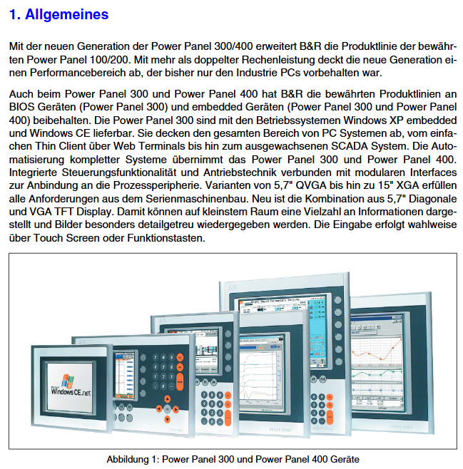
The B&R Power Panel 300/400 series touch screen is a human-machine interaction terminal designed specifically for industrial automation scenarios, covering multi scenario requirements from basic control to complex automation. Its core advantages focus on three dimensions: high compatibility, industrial grade reliability, and flexible scalability, which can be summarized into six key features:

Dual product line adapts to diverse needs: divided into Power Panel 300 (basic type) and Power Panel 400 (extended type). The former focuses on basic human-computer interaction, while the latter supports 1-2 aPCI slots, expandable communication modules or function cards, meeting the needs from simple data display to complex control integration.

Industrial grade environmental tolerance: The front side protection level reaches IP65/NEMA 250 Type 4X, dustproof and water-resistant; Working temperature coverage -20~+50 ° C (some models support -20~+70 ° C storage), anti vibration (2-200Hz, 0.5-2g amplitude), anti impact (15-30g, 11-15ms half sine wave), suitable for harsh industrial sites.

Flexible hardware configuration: equipped with Geode LX800 500MHz processor, supporting 128-512MB DDR SDRAM memory and Type I CompactFlash storage expansion; The display size covers 5.7 inches (QVGA/VGA) to 15 inches (XGA), including various screen types such as monochrome LCD, color LCD, color TFT, etc. Some models integrate resistive touch screens (Elo Accu Touch/Unze technology), with a light transmittance of 80% ± 5%.

Rich communication and interfaces: standard 10/100Mbps Ethernet (Intel 82551ER controller), RS232 serial port (16C550 compatible, maximum 115kBaud), 2 USB 2.0 interfaces (maximum 500mA power supply per port); The Power Panel 400 additionally supports aPCI slots and can expand fieldbus modules (such as CAN, Profinet, etc.) to meet the interconnection needs of industrial equipment.

Dual Run Mode Switching: Supports OS Mode (regular operating system startup, such as Windows CE/XP Embedded) and AR Mode (automatic runtime startup, adapted to B&R Automation Runtime) through BIOS Boot Mode switch, meeting the startup logic requirements in different control scenarios.

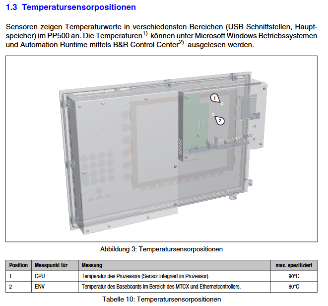
Convenient maintenance and diagnosis: equipped with Mode/Mode dip switch (supports Boot/Mode/Dyn. Mode/Diagnosis four modes), status LED (Power/User/CF indicator light), external Reset/Power button; Support reading key data such as CPU and ambient temperature through B&R Control Center, enabling fast and efficient fault location.

Core components and functional details of the product

(1) Core hardware components and classification

According to functional positioning and hardware configuration, products are mainly divided into three categories, and the differences in core parameters of each model are shown in the following table:

Product Category Represents Model Core Configuration Differences Applicable Scenarios

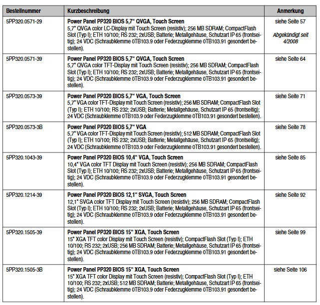
Power Panel 300 (BIOS version) 5PP320.0571-29 and 5PP320.1505-39 only support BIOS startup and do not have an aPCI slot; The memory is mostly 256MB, with some models (such as 5PP320.1505-3B) reaching 512MB; the display size is 5.7-15 inches, and some scenarios include touch screen basic data monitoring, simple device control, and no need for extended functions

Power Panel 300 (Automation Runtime Edition) 4PP320.0571-01, 4PP381.1043-31 pre installed with Automation Runtime system, without aPCI slot; 128MB memory, supports CompactFlash storage; Some models (such as 4PP381.1043-31) integrate 28 function keys with LED indicator lights that need to be linked with the B&R automation system, focusing on operational control scenarios

Power Panel 400 (Automation Runtime Edition) 4PP420.0571-45, 4PP451.1043-75 supports 1-2 aPCI slots and expandable communication modules; 128MB memory (some older versions 64MB), 512kB SRAM (battery backup, supports data saving in case of power failure); Integrate more function keys (such as the 4PP451 series with 16 function keys and 6 soft keys) into complex automation systems, requiring the expansion of fieldbus and multi device linkage control scenarios (such as production line control and equipment cluster monitoring)

(2) Key functional characteristics

1. Display and input functions

Screen performance: Different screen sizes have differentiated design parameters, such as 5.7-inch QVGA color TFT (4PP320.0571-35) with a contrast ratio of 350:1 and brightness of 500cd/m ², and 15 inch XGA color TFT (4PP320.1505-31) with a contrast ratio of 400:1 and brightness of 250cd/m ², all of which support screen rotation function and are suitable for horizontal/vertical installation requirements.

Touch and buttons: The resistive touch screen supports 12 bit precision and has a click life of over 10 ⁶ times; The function keys adopt industrial grade design, with a pressure range of 1 ± 0.3~3 ± 0.3N. Some models (such as the 4PP481 series) include plug-in key strips with customizable labels for easy on-site identification and maintenance.

2. Power supply and protection design

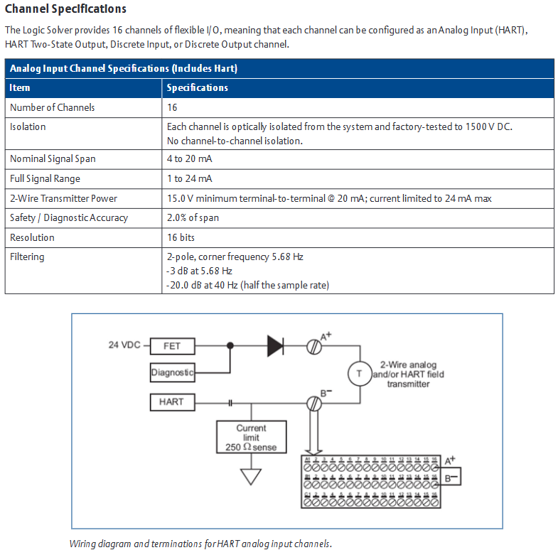
Power supply and isolation: Input voltage 18-30VDC, supporting reverse polarity protection; Each channel is optically isolated from the system (1500VDC test), and the USB interface is protected by a “USB current limit switch” (maximum 500mA per port) to prevent external device overload damage.

Heat dissipation and durability: adopting passive heat dissipation (heat sink) and fanless design to reduce dust accumulation; The shell is made of anodized aluminum material, and the sealing strip on the front side is waterproof, suitable for long-term industrial operation.

3. Diagnostic and maintenance functions

Status monitoring: Real time display of device status through LED indicator lights (Power light green=power supply normal, red=standby; CF light yellow=storage read/write in progress); Support reading CPU temperature, memory usage, and other data through B&R ADI (Automation Device Interface), triggering alarms in case of abnormalities.

Convenient maintenance: CompactFlash slot with locking buckle and ejector, supports power-off replacement; BIOS supports the “restore default value” function (set the Mode/Mode switch to 00 and reset three times), simplifying the fault recovery process.

Hardware specifications and environmental parameters

(1) General Electric and Physical Specifications

Category parameter details (universal type, some models have differences)

Processor Geode LX800 500MHz, 32-bit x86 architecture, supports MMX/3D Now! instruction set

128-512MB DDR SDRAM memory, 8MB shared video memory (for graphics card)

Storage Type I CompactFlash slot (supports 64MB-16GB SLC NAND Flash)

Communication interface 1 x Ethernet (RJ45, 10/100Mbps), 1 x RS232 (9-pin D-Sub), 2 x USB 2.0 (Type A)

Power input 18-30VDC, rated current 0.45-1.25A (depending on model), power 10-30W

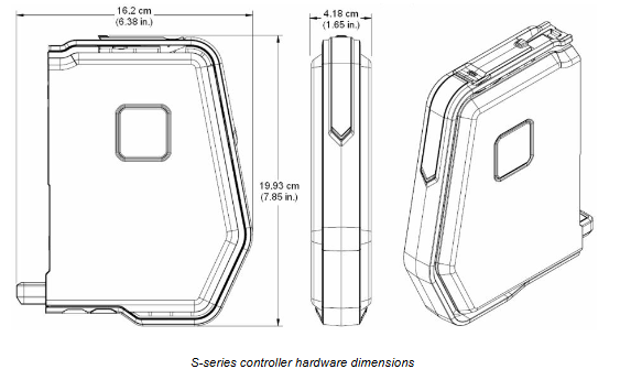
Physical size 5.7 inches model: 212 × 156 × 55.5mm (width × height × depth); 15 inch model: 435 × 330 × 71.5mm

The weight of the 5.7-inch model is approximately 1.4-1.7kg, and the 15 inch model is approximately 6.3kg (excluding expansion modules)

(2) Environmental and Protection Parameters

Category parameter details

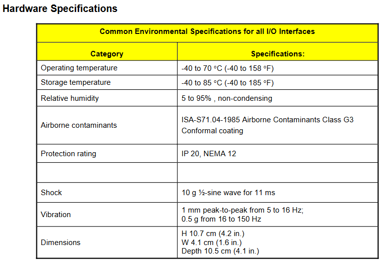
Working temperature 0~+50 ° C (some models such as 4PP320.1043-31 support -20~+50 ° C)

Storage temperature -20~+70 ° C

Relative humidity of 5%~95% (no condensation), in compliance with ISA-S71.04-1985 G3 level pollution protection

Protection level: Front side IP65, Rear side IP20 (requires insertion of CF card or aPCI module)

Anti vibration operation: 2-9Hz (1.75mm amplitude), 9-200Hz (0.5g); Storage: 2-8Hz (7.5mm amplitude), 8-200Hz (2g)

Anti impact operation: 15g (11ms); Storage/Transportation: 30g (15ms)

The maximum altitude is 3000m (for every 1000m increase, the maximum working temperature decreases by 1 ° C)

Order information and system compatibility

(1) Core Product Order List (Key Models)

Product Category Model Description Remarks

Power Panel 300 (BIOS version) 5PP320.0571-29 5.7-inch QVGA color LCD with touch screen, 256MB memory including 1 CF slot, no aPCI slot

5PP320.1505-39 15 inch XGA color TFT with touch screen, 256MB memory, front side IP65, supports screen rotation

Power Panel 300 (AR version) 4PP320.1043-31 10.4-inch VGA color TFT, with touch screen, 128MB memory compatible with B&R Automation Runtime, including 6 fixed buckles

4PP381.1043-31 10.4-inch VGA color TFT with touch screen and 28 function keys supporting aPCI expansion, suitable for complex operation scenarios

Power Panel 400 (AR version) 4PP420.0571-75 5.7-inch QVGA color TFT, with touch screen, 1 aPCI slot, 128MB memory, including lithium battery (3V/950mAh)

4PP451.1043-75 10.4-inch VGA color TFT with 10 soft keys+28 function keys and 2 aPCI slots, compatible with multi bus integration

Spare part 0AC201.91 lithium battery (3V/950mAh, 4 pieces/box) for RTC clock and SRAM data backup

5CFCRD.2048-04 2GB Type I CompactFlash Card (SLC NAND) industrial grade storage, compatible with all models

0TB103.9 24V 3-pin screw terminal power plug needs to be ordered separately for power connection

(2) System compatibility requirements

Software compatibility: Supports Windows CE 5.0/6.0 (Professional/ProPlus version) Windows XP Embedded(Feature Pack 2007)、Windows Embedded Standard 2009; Automation Runtime needs to be configured with B&R Automation Studio software.

Hardware compatibility: aPCI slots only support B&R System 2005 series modules (such as CANopen, Profinet modules); CompactFlash should use industrial grade SLC type (recommended original B&R model to avoid compatibility issues); External devices must comply with USB 2.0 specifications or RS232 protocol (such as barcode scanners, printers).

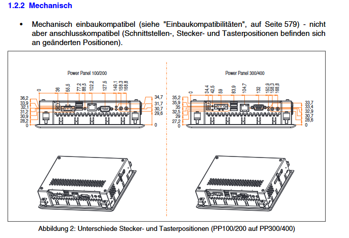
Installation compatibility: Compatible with the mechanical installation dimensions of Power Panel 100/200 (with the same hole size), but with different interface positions (such as rotating the power plug 180 °), requiring rewiring.

Emerson S-series Mass Connection Solutions

Core positioning and core advantages

The DeltaV S series large-scale connectivity solution is an efficient cabling system designed specifically for S series traditional I/O cards, enabling fast and reliable connections between field devices and DeltaV single redundant/redundant high-density I/O cards. Its core advantages can be summarized as seven key features:

Fast and error free cabinet wiring: Single redundant/redundant high-density I/O cards are connected to large-scale connection boards through ribbon cables, which can be completed within seconds without the need for tools, eliminating the need for additional cross wiring inside the cabinet and significantly reducing labor costs and wiring error risks.

Modular design enhances reliability: The connection board adopts modular signal splitting (up to 16 signals per block), which is more stable compared to traditional solutions, reduces the impact of single point failures on the overall system, and improves the reliability of the wiring system.

Reducing terminal footprint: Integrating all components required for cabinet wiring into a single connection board, combined with flexible installation methods (adapted to different cabinet layouts), significantly optimizes cabinet space utilization and reduces overall equipment footprint.

Significantly reduce manual workload: achieve flexible connection between I/O cards and connection boards based on 1:1 ribbon cables, without the need for additional cross wiring; On site equipment is directly connected to the connection board through screw terminals, simplifying the wiring process and shortening the construction period.

Significant cost reduction: Ready made ribbon cables (up to a maximum length of 3m) can be used inside the cabinet, and 6m standard circular ribbon cables can be used for cross cabinet connections, eliminating the need for customized special cables and reducing material costs; The reduction of labor and time costs further compresses overall investment.

Full signal type circuit disconnection function: The analog (AI/AO) connection board adopts a blade type disconnection design with 2mm test holes, which does not require interruption of the process when maintaining or calibrating 4-20mA circuit signals; The DI/DO connection board achieves on-site circuit power disconnection through replaceable fuses, facilitating maintenance operations.

Discrete signal terminal fault detection: When the DI/DO Plus connection board is paired with the new Plus I/O card, the DeltaV diagnostic function can detect power or cable faults; The onboard jumper supports disabling this function during process operation, facilitating rewiring and ensuring flexibility in troubleshooting and maintenance.

Core components and functional details of the product

(1) Core hardware components

Component Name Adaptation I/O Card Type Function Description Key Features

AI/AO Plus large-scale connection board S series Plus single redundant/redundant 16 channel AI/AO card connects 4-20mA HART field devices with 16 channels of I/O cards, supporting 2-wire/4-wire devices (3-row screw terminals, channel level optional); Circuit disconnection function with 2mm test holes per channel; Connect the I/O card through a 24 pin ribbon cable (≤ 3m) or a 48 pin special circular ribbon cable (>3m)

DI Large scale Connection Board (Single Redundancy) S Series Single Redundancy 32 Channel 24V DC Dry Contact DI Card Connection 24V DC Discrete Input Signal (Dry Contact/Isolation Signal) Each set includes 2 boards, each with 16 channels (2 rows of screw terminals); Yellow LED channel status indicator; Replaceable fuse (used to disconnect the on-site power supply during maintenance); Connect the I/O card through a 20 pin ribbon cable (≤ 3m) or a 20 pin standard circular ribbon cable (>3m)

DI Plus large-scale connection board (redundant) S series redundant 32 channel 24V DC dry contact DI Plus card connects 24V DC discrete input signals, supports fault detection. Each set includes 2 boards, each with 16 channels (2 rows of screw terminals); Equipped with all the features of DI large-scale connection board, and additionally integrated terminal fault detection function (detecting power/cable faults); Onboard jumper can disable fault detection (used for wiring during operation); The I/O card resource manager view contains 2 fault detection parameters, and when enabled, the diagnostic system automatically marks abnormal signals

The DO Plus large-scale connection board S series single redundant/redundant 32 channel 24V DC high side DO card connects discrete output devices (24V DC high side relay output/no voltage relay contacts). Each set contains 4 boards, and every 2 daisy chain connections achieve 16 channels (screw terminals); Yellow LED channel status indicator; Replaceable fuses (disconnect power during maintenance); Integrated terminal fault detection function (with redundant DO Plus card); Onboard jumper can disable fault detection; Connect the I/O card through a 20 pin ribbon cable (≤ 3m) or a 20 pin standard circular ribbon cable (>3m)

All connection plates of circular ribbon cables (in cross cabinet scenarios) enable long-distance connection of 20 pins (discrete signal, 6m) and 48 pins (analog signal, 6m) across cabinets; Supports working temperature range of -20~70 ° C, wire specification of 0.14mm ² (26 AWG), compliant with ISA-S71.04-1985 G3 anti-corrosion standard

(2) Key functional characteristics

Signal adaptation and connection flexibility:

Analog Channel: Supports 4-20mA HART signals, and 2-wire/4-wire devices can independently select wiring methods according to channels to meet different on-site instrument requirements.

Discrete channel: DI supports 24V DC dry contacts and isolation signals, DO supports 24V DC high side output and no voltage contacts, fuse position can be switched by jumper to output types, suitable for various discrete devices.

Maintenance convenience:

Circuit disconnection: The blade type disconnection design of the AI/AO board can be directly connected to the testing equipment, and the replaceable fuse of the DI/DO board is convenient for cutting off the on-site power supply without interrupting the overall process.

Status indication: The yellow LED displays the real-time on/off status of discrete channels, which can quickly locate the problematic channel in case of a fault and simplify the troubleshooting process.

Fault detection and safety design:

The terminal fault detection function of DI/DO Plus board, combined with Plus I/O card, can monitor the power and cable status in real time. When abnormal, the diagnostic system automatically marks it, reducing the time for troubleshooting.

Onboard isolation design: DI board on-site wiring and I/O card circuit optical isolation (1000VDC test for 2 seconds), DO board relay contacts are isolated from the system (250V AC, 3600VDC test) to ensure system safety.

Hardware specifications and compatibility

(1) Universal environmental specifications (all connection boards)

Category parameter details

Working temperature -20~70 ° C (when the DO board is above 60 ° C, it needs to be downgraded to 3A/channel)

Storage temperature -40~85 ° C

Relative humidity 5%~95% (no condensation)

Pollutant level ISA-S71.04-1985 G3 level (with conformal coating)

Protection level IP20

Anti impact 10g half sine wave (continuous for 11ms)

Vibration 2~13.2Hz (1mm peak to peak), 13.2~150Hz (0.7g)

(2) Core component dimensions and electrical specifications

Component type size (length x width x height, mm) Key electrical parameters

AI/AO Plus board 118.06 × 109.78 × 60.52 channel type: 4-20mA HART; 16 channels

DI board 102.82 × 110.05 × 44.1 channel type: 24V DC dry contact/isolation; Conduct detection>2mA, shutdown detection<0.25mA; input impedance 5k Ω; on-site power supply 24V DC ± 10% (typical 75mA, maximum 100mA)

DO Plus board 133.3 × 109.75 × 60.52 channel type: 24V DC high side/relay contact; Output rated 5A/channel (250V AC/24V DC), board maximum 10A; on-site power supply 24V DC ± 10% (maximum 10A)

Round ribbon cable with a length of 6m and a wire specification of 0.14mm ² (26 AWG); 20 needles (50 threads/25 pairs), 48 needles (50 threads/25 pairs); Working temperature -20~70 ° C

(3) System compatibility

I/O card adaptation: Only supports DeltaV S series traditional I/O cards, including single redundant/redundant 32 channel DI/DO cards, 16 channel AI/AO Plus cards, which need to be ordered together with the connection board (refer to the “S Series Traditional I/O Product Manual” to confirm the model).

Software requirements: The fault detection function needs to be paired with the DeltaV diagnostic system, and the I/O card parameter configuration is completed in the DeltaV resource manager. There are no additional software version requirements (compatible with mainstream DeltaV versions).

Ordering information and spare parts

(1) Core Product Order List (Some Key Models)

Product Category Description Model Remarks

Connection board kit AI/AO Plus large-scale connection solution (1 board) – needs to be ordered as a set with the S series 16 channel AI/AO Plus card, refer to the I/O card PDS to confirm the complete model

DI Large scale Connection Solution (2 boards) – To be ordered as a complete set with S series single redundant 32 channel DI card

DI Plus Large scale Connection Solution (2 boards) – To be ordered as a complete set with S-series redundant 32 channel DI Plus card

DO Plus Large scale Connection Solution (4 boards) – To be ordered as a complete set with S series single redundant/redundant 32 channel DO cards

Circular ribbon cable 20 pin circular ribbon cable (6m, 2 pieces/set) SE4000L6P20 discrete signal cross cabinet connection, needs to be ordered separately

48 pin special circular ribbon cable (6m, 1 piece) SE4000L6P48 analog signal cross cabinet connection, needs to be ordered separately

(2) Spare parts information

Spare parts description, model, and remarks

AI/AO Plus connection board KJ4007X1-BD1 single block replacement

DI connection board KJ4007X1-BA1 single block replacement

DI Plus connection board KJ4007X1-BB1 single block replacement

DO Plus Connection Board KJ4007X1-BC1 Single Block Replacement

DI board main fuse (125V AC/1A, 10 pieces/box) KJ4007X1-DB1 compatible with DI/DI Plus board

DI board channel fuse (125V AC/160mA, 10 pieces/box) KJ4007X1-DA1 compatible with DI/DI Plus board

DO board main fuse (125V AC/10A, 10 pieces/box) KJ4007X1-DD1 compatible with DO Plus board

DO board channel fuse (250V AC/5A, 10 pieces/box) KJ4007X1-DC1 compatible with DO Plus board

(3) Third party products (optional)

Describe Phoenix Contact model and product type

20 pin circular ribbon cable (0.5m) 2296391 FLK 20/EZ-DR/50KONFEK

20 pin circular ribbon cable (1.0m) 2296401 FLK 20/EZ-DR/100KONFEK

20 pin circular ribbon cable (3.0m) 2296498 FLK 20/EZ-DR/300KONFEK

20 pin circular ribbon cable (10.0m) 2296537 FLK 20/EZ-DR/1000KONFEK

48 pin circular ribbon cable (xm) – CABLE-50/2FLK24/2FLK24/xM/S

Emerson DeltaV SIS Logic Solver (SLS1508)

Core positioning and core advantages

The DeltaV SIS Logic Solver (SLS1508) is the core component of Emerson’s Intelligent Safety Instrumented Systems (SIS), designed specifically for industrial process safety protection and meeting SIL 1-3 safety functional requirements. Its core advantages can be summarized into six key features:

The world’s first intelligent SIS logic solver: communicates with intelligent field devices through the HART protocol to diagnose faults in field instruments and final control components in advance (according to research, such faults account for more than 85% of SIS faults), avoiding false tripping, improving process availability, and reducing full lifecycle costs.

Integrated but independent with the control system: strictly follow safety standards, use dedicated hardware, software, and networks to implement safety functions, and eliminate the impact of common cause failures; Simultaneously achieve seamless integration of configuration, maintenance, and operating environment at the workstation level, balancing security and usability.

Easy to comply with IEC 61511 standard: provides strict user management functions, automatically verifies data for changes initiated by the human-machine interface (HMI) (such as trip limit modification), ensures accurate data writing into the target logic solver, and meets the strict requirements of the standard for change control.

Suitable for any scale of application: Whether it is an isolated wellhead or a large emergency shutdown (ESD)/fire and gas system, it can be flexibly expanded to cover SIL 1-3 safety functions; Each logic solver is equipped with dual CPUs and 16 I/O channels, allowing for system expansion without the need for additional processors. The scanning rate and memory usage are not affected by system size and remain stable.

SIL 3 certification and redundant architecture: The SLS1508 logic solver meets SIL 3 application requirements with a single unit, and the availability is higher when installed in pairs with redundancy; The redundant architecture includes dedicated redundant links, independent power supply, I/O redundant peer-to-peer links for real-time release, and dual machine shared input data to ensure reliable system operation.

Support for online addition of logic solvers: The system automatically detects new hardware every scanning cycle and can add devices to the online system in real-time without interrupting the process; Once the newly added device is recognized by DeltaV Resource Manager, it can be directly configured, greatly improving the flexibility of system expansion.

Core components and functional details of the product

(1) Core hardware components and system architecture

Component Name Function Description Key Features

SLS1508 logic solver core safety logic operation unit, provides I/O interface with built-in dual CPU, 16 configurable I/O channels (discrete input/output, analog input (HART), HART dual state output), supports single SIL 3 application, and occupies 4 slots for redundant paired installation

The redundant terminal block connects the on-site wiring and logic solver to adapt to the SLS1508 redundant architecture, enabling redundancy without the need for additional control strategy configuration. The system automatically identifies redundant pairs

SISnet repeater extends the communication range of SISnet and realizes remote logic solver communication through fiber optic ring network. It is divided into two independent fiber optic rings, primary and backup. Please refer to the separate product manual for details

The carrier extension cable extends the local bus power and signal connection between 8-wide carriers, ensuring signal transmission between the controller, logic solver, and SISnet repeater

Local peer-to-peer bus extension cable extends SISnet communication between logic solvers on different carriers, supports interconnection of logic solvers across carriers, and builds a local SISnet network

The wide terminal carrier terminates the local peer-to-peer bus installed at the end of the carrier chain, providing SISnet bus terminal matching to ensure stable communication

The 8-width carrier carries logic solvers, SISnet repeaters, and other components. The logic solvers are installed in odd numbered slots (1/3/5/7) and support connecting multiple carriers through expansion cables

(2) Communication Network Design

Control Network: Implement communication between DeltaV network nodes, as detailed in the DeltaV Digital Automation System Installation Manual.

Local Bus: connects DeltaV controllers with logic solvers, SISnet repeaters, and transmits control and configuration signals.

Local Peer to Peer Bus (SISnet): a dual channel bus where logic solvers communicate with each other and with local SISnet repeaters through a carrier, and the same message is broadcasted on both channels; The two ends of the bus need to be terminated (the left end through a 2-wide power/controller carrier, and the right end through a 1-wide terminal carrier), and the repeater can be flexibly installed at any position on the bus.

Remote Peer Ring: SISnet repeaters hosted by different controllers communicate through fiber optic ring networks. Local repeaters aggregate global variable messages and transmit them along the ring network. Receiver repeaters broadcast and forward them on the local SISnet, while global messages are transmitted only once along the ring network. The primary and backup repeaters form independent fiber optic rings.

(3) Unique redundancy mechanism

Redundant operation mode: The redundant SLS1508 dual machine always runs in parallel, reading I/O inputs, executing safety logic, and driving outputs, without distinction between master and backup/master-slave; Only one (Active state, indicator light on) communicates with the workstation and SISnet, while the other (Standby state) only connects to SISnet.

Fault handling: When a single machine detects a fault, it automatically enters a failure state, and all output channels are powered off, but it does not affect the operation of another machine (continuing to read and write I/O, executing logic), and redundant switching is completely undisturbed; In safe areas, faulty modules can be replaced with electricity, while in hazardous areas, specific installation procedures must be followed.

Integrity alarm: Real time monitoring of redundant pair status, triggering alarm scenarios including: hardware failure of logic solver, communication failure between logic solver and SISnet, communication failure between redundant pairs, communication failure between logic solver and DeltaV controller, and removal of logic solver from carrier; Alarm information and device status can be viewed in the diagnostic browser.

Automatic verification testing: Redundancy can be configured for automatic verification testing. After setting the testing interval, the system will automatically execute and issue a warning to the operator before testing to ensure the effectiveness of safety functions.

(4) Sequence of Events (SOE) function

Basic function: Automatically generate events when executing function blocks during the module scanning cycle, with a timestamp resolution of<1ms, and record them in the event log in the order of occurrence; Standard functional blocks (input block, voting block, cause and effect block, etc.) can automatically generate events (such as I/O faults, trip limit triggering, first output signal) without special configuration, and record the simulated values and triggering conditions during tripping.

First out positioning: When the factory emergency stops, the “first out trip” signal in the event log can be filtered to quickly locate the first input that triggers the trip, simplifying fault diagnosis.

High resolution extension: If higher temporal resolution (0.25ms) is required, the channel can be simultaneously connected to SLS1508 and DeltaV discrete input SOE cards.

Hardware specifications and I/O channel parameters

(1) General Environment and Physical Specifications

1. SLS1508 Universal Environment Specification

Category parameter details

Working temperature -40~70 ° C (-40~158 ° F), long-term high-temperature operation shortens lifespan

Storage temperature -40~85 ° C (-40~185 ° F)

Relative humidity 5%~95% (no condensation)

Pollutant level ISA-S71.04-1985 G3 level (with conformal coating)

Protection level IP20

Hazardous Area Certification: European EMC Directive (EN61326-1, Criterion A), NAMUR NE21 EMC Requirements, Low Voltage Directive (IEC 61010-1), FM Class I Div 2 (Groups A-D, T4, No Arc) ATEX 3 G EEx IIC-nA T4(EN50021:1999)、CSA 1010

Anti impact 10g half sine wave (continuous for 11ms)

Vibration 5-16Hz (1mm peak to peak), 16-150Hz (0.5g)

2. SLS1508 Physical and Electrical Specifications

Project parameter details

Input power supply 24V DC ± 20%, 1.0A (basic power consumption)+on-site power supply (total power consumption 5.0A); Suggest using an independent power supply with DeltaV controller/I/O

The maximum on-site power supply is 4A (actual value depends on channel type and on-site equipment)

Isolation level: Each channel is optically isolated from the system (1500VDC factory test), and there is no isolation between channels

No local bus current

Installation method: SIS (yellow) terminal block on a wide carrier with odd numbered slots; Redundant occupation of 4 slots

Redundancy for weight 1.20kg

Redundancy for heat consumption of 24W

Redundancy for 24V power consumption DC@2A +Digital output on-site load

Dimensions (Front/Side) 83.8mm (3.3 inches)/110.0mm (4.3 inches)

(2) Detailed parameters of I/O channels

1. Analog input channel (including HART)

Project parameters

Number of channels 16

Isolate each channel from the system’s optical isolation (1500VDC test), with no isolation between channels

Nominal signal range 4~20mA

Full signal range 1-24mA

When the 2-wire transmitter is powered by 20mA, the minimum voltage between terminals is 15.0V, and the maximum current limit is 24mA

2.0% of the safety/diagnostic accuracy range

Resolution 16 bits

Filter 2nd order, cut-off frequency 5.68Hz (-3dB), at 40Hz (1/2 of sampling rate) -20.0dB

2. HART dual state output channel

Project parameters

Number of channels 16

Isolate each channel from the system’s optical isolation (1500VDC test), with no isolation between channels

The nominal signal range is 20mA for conduction and 0 or 4mA for shutdown (configurable)

Full signal range 0~24mA

5.0% of the safety/diagnostic accuracy range

Resolution of 12 bits

Compliant voltage 20mA@600 Ω load

Triggered when the open-loop detection output deviates from the configured value by 15% and the current is less than 1.0mA

3. Discrete input channel

Project parameters

Number of channels 16

Isolate each channel from the system’s optical isolation (1500VDC test), with no isolation between channels

Conductivity detection ≥ 2mA

Shutdown detection ≤ 1.65mA

The input impedance is about 1790 Ω

Input compatibility NAMUR sensor (12V), dry contacts, dry contacts with terminal resistors

Line fault detection (short circuit, optional) with resistance<100 Ω and current>6mA

Line fault detection (open circuit, optional) with current<0.35mA when resistance>40k Ω

The fault detection configuration requires channel level activation, and the dry contact requires an external 12k Ω parallel resistor (open circuit detection) and a 2.4k Ω series resistor (short circuit detection). The NAMUR sensor does not require an external resistor

4. Discrete output channels

Project parameters

Number of channels 16

Isolate each channel from the system’s optical isolation (1500VDC test), with no isolation between channels

Output voltage: On site power supply voltage -2V

On site power supply with continuous 0.5A per channel, maximum 4.0A per card

Output load 56~3500 Ω

Turn off leakage current open-loop test on: 7.8mA; open-loop test off: typical 4.5 μ A, maximum 10 μ A

Short circuit protection current limit typical 2.0A

Line fault detection (short circuit): Under 24V DC on-site power supply, the resistance is less than 5 Ω for more than 1 second

Line fault detection (open circuit): Under 24V DC on-site power supply, resistance>25k Ω (open circuit detection),<3.5k Ω (no open circuit detection)

Pulse testing is recommended to be enabled (apply 1ms of 24V DC pulse every 50ms), and devices such as solid-state relays that do not support it can be disabled

Ordering Information and Preconditions

(1) Core Product Order List

Product Description Model

DeltaV SLS1508 Redundant Logic Solver (including Terminal Block) VS3202

1 wide SISnet terminal component (including right expansion card and 2 terminal resistors) VS6051

SIS database extension VS1508

8-width carrier with expansion cable assembly (including left and right expansion cards, 2 logic solver communication buses coaxial, 1 carrier backplane communication cable) VE4050E1C2

2 Wide Carrier (Improved Type, Including Bus Terminal) VE3051C0

(2) Pre requirements

Software version: DeltaV v8.3 or above is required.

2-Width Power/Controller Carrier: Upgraded version after 2004 (with white rectangular markings on the board, located between the power module and MD controller), model KJ4001X1-BA3 and above; The old version (marked with white dots) does not support downloading logic solver programs.

MD controller: Model must be 12P2093X082 or above, early models do not support DeltaV SIS system.

Emerson DeltaV Ethernet I/O Card (EIOC)

Core positioning and core advantages

DeltaV Ethernet I/O Card (EIOC) is an embedded data server designed specifically for DeltaV systems to access external Ethernet device networks. It supports multiple industrial Ethernet protocols and can directly communicate with third-party Ethernet devices (such as PLCs, motor control centers, intelligent electronic devices, etc.) to achieve data acquisition and device control. Its core advantages can be summarized as seven key features:

Direct connection to Ethernet device network: No intermediate gateway is required, and external Ethernet devices can be directly connected through Modbus TCP, EtherNet/IP, IEC 61850 MMS, OPC UA client, and EtherNet/IP control tag integration protocol. It supports device monitoring and control, operates independently of DeltaV controller, and reduces system complexity.

High capacity and scalability: The license mode based on the number of device connections adapts to different needs, and the data access capability varies with the protocol: under the Modbus TCP/Ethernet/IP/IEC 61850 MMS protocol, up to 256 devices and 32000 signals can be accessed; Under the OPC UA client protocol, up to 64 servers and 30000 real-time signals can be accessed; Under the EtherNet/IP control tag integration protocol, up to 256 devices and 2000 tags (10 signals per tag) can be connected to meet the requirements of large-scale industrial scenarios.

Complete monitoring and control functions: The accessed data can be processed in the built-in control module of EIOC, supporting alarm generation, historical data collection, and operator interface display. The functions are consistent with traditional DeltaV controllers; Supports discrete control and limited PID control function blocks, without the need to allocate them to DeltaV controllers, and can directly control Ethernet devices such as motors, switchgear, and frequency converters.

Powerful processing capability: A single EIOC can run up to 2000 control modules, and the system supports up to 60 EIOCs directly connected to the DeltaV control network, flexibly achieving network isolation and adapting to complex factory network architectures.

Flexible network configuration: Users can manually configure the IP address of Ethernet device networks to adapt to various factory network solutions; The simplex design requires EIOC to be on the same IP subnet as the device, while the redundant design requires EIOC primary and backup ports to be on different subnets (following best engineering practices); Support for Parallel Redundancy Protocol (PRP), seamless switching in case of redundant network failure, zero recovery time, and elimination of single point of failure.

Usability design: Native integration with DeltaV system, supporting 5 protocol choices (only 1 at a time, corresponding license required), EIOC and driver updates included in DeltaV system updates; The configuration is completely completed in DeltaV Explorer and Control Studio, consistent with the traditional I/O signal configuration process. The data can be accessed through the DeltaV Live/Operate interface and historical database, reducing the cost of operation and maintenance learning.

Modular redundancy design: The dual level carrier integrates redundant power input terminals and redundant Ethernet isolation ports. Adding one EIOC can achieve redundant configuration, and the system automatically identifies redundant pairs; Redundant Ethernet ports isolate communication between the DeltaV control network and Ethernet device networks, supporting manual triggering of switches in the DeltaV diagnostic browser to ensure high system availability.

Core components and functional details of the product

(1) Core hardware components

Component Name Function Description Key Features

EIOC card embedded data server, realizing communication with Ethernet devices and DeltaV control network. Single card supports 2000 control modules, input power 24V DC ± 10% (single redundancy 325mA max, dual redundancy 575mA max), heat consumption single redundancy 7W max, dual redundancy 13W max, with power/error/main/backup status/communication status LED indicator lights

Double horizontal carrier DIN rail horizontal installation, supporting 1 (single redundancy) or 2 (double redundancy) EIOC cards and auxiliary components, providing redundant 24V DC power interface (1A max) and redundant Ethernet isolation port (copper cable 10/100BASE-TX, RJ45100m), including universal carrier protection cover

Ethernet isolation port enables physical isolation between DeltaV control network and Ethernet device network, supporting only copper twisted pair cables and connected through RJ45 interface to ensure network security and signal stability

The power plug provides 24V DC power input for the carrier and EIOC to adapt to redundant power configuration, ensuring reliable power supply

(2) Support protocols and key functions

1. Core Industrial Ethernet Protocol

Protocol type adaptation equipment key function data access capability

Modbus TCP PLC、 Motor Control Centers (MCC), analyzers, and other Modbus TCP devices (or Modbus serial devices connected through gateways) use EIOC as Modbus clients to read coil/discrete input/input register/hold register data and write coil/hold register data; Only supports MODICON (PLC) addressing, register addresses have range limitations (such as coil 1-9999), 256 devices, 32000 signals

EtherNet/IP PLC、 Intelligent field devices (IFDs), frequency converters, MCCs, etc. support implicit (Class 1) and explicit (Class 3) communication and are compatible with Class 1/3 I/O adapters; Support Class 3 PCCC and UCMM (with Logix tags) message classes; Redundant communication requires special configuration (refer to the DeltaV System Planning Guide) with 256 devices and 32000 signals

IEC 61850 MMS motor protection relays, motor starters MCC、 Intelligent electronic devices (IEDs) such as switchgear use EIOC as MMS clients to read and write real-time signals; Not supporting historical data reading and GOOSE application. 256 devices, 32000 signals

OPC UA client OPC UA server (third-party device or system) follows OPC UA 1.03 standard, supports Data Access (DA) protocol, and only processes real-time data; Supports 128/256 bit encryption, message signing, and digital certificates (self signing/CA authentication). 64 servers and 30000 signals can be configured for online/offline browsing through NodeSet files

EtherNet/IP control tag integration ControlLogix, CompactLogix and other tag based PLCs access data through tag names based on EtherNet/IP Class 3 messages (without register mapping); Support string signal reading and array reading/writing (up to 64 elements per array, up to 100 arrays per EIOC); Only supports controller scope labels, does not support program labels. 256 devices, 2000 labels (10 signals per label, for a total of 20000 signals)

2. Parallel Redundancy Protocol (PRP)

Function: Ethernet redundancy protocol, primary and backup network ports communicate simultaneously, devices receive the same data through dual paths, zero switching time in case of failure, eliminating redundant network single point failures, suitable for high availability demand scenarios (such as IEC 61850 MMS electrical monitoring).

Usage conditions: The device must have native support for PRP; Non PRP devices need to be connected through RedBox to avoid abnormal diagnostic status; PRP is independent of application protocols and can be used in conjunction with all EIOC supported protocols without the need for additional licenses.

(3) Control module and functional block limitations

Control module capability: A single EIOC can run up to 2000 control modules, supporting basic functional blocks such as alarm detection, AI/AO/DI/DO tag I/O, logical operations, mathematical calculations, timers/counters, etc. The module execution rate can be selected from 100ms-60s.

Function block restrictions:

Supports a limited number of specific functional blocks: 256 DC/EDC/DCC (motor control), 26 PID (analog control), 16 SEQ (stepper), 16 STD (state transition diagram).

Unsupported functions: Batch control, SFC (Sequential Function Diagram), PLM (Process Logic Manager), equipment module, complex control requires PK controller or VIM2 card.

Hardware specifications and compatibility

(1) General Environment and Hardware Specifications

1. General environmental specifications (all components)

Category parameter details

Working temperature -40~70 ° C (-40~158 ° F), long-term high-temperature operation will shorten the service life

Storage temperature -40~85 ° C (-40~185 ° F)

Relative humidity 5%~95% (no condensation)

Protection level IP20

Pollutant level ISA-S71.04-1985 G3 level (with conformal coating)

Anti impact 10g half sine wave (continuous for 11ms)

Vibration 2~13.2Hz (1mm peak to peak), 13.2~150Hz (0.7g)

2. Core hardware dimensions and electrical parameters

Component size/electrical parameters

EIOC card height 13.7cm (5.39 inches), depth 17.4cm (6.85 inches), width 2.9cm; input power supply 24V DC ± 10%, built-in non replaceable fuse

Dual level carrier compatible with horizontal T-shaped DIN rail, Ethernet isolation port spacing of 6.1cm (2.41 inches), protective cover compatible with redundant slots

Ethernet isolation port supports 10/100BASE-TX, RJ45 interface, transmission distance of 100m

(2) System compatibility and certification

Compatibility requirements:

Software version: Modbus TCP/Ethernet/IP/IEC 61850 MMS requires DeltaV v13.3.1 or higher; OPC UA client/EtherNet/IP control tag integration/PRP requires v14. LTS or above.

Controller adaptation: Supports communication with M-series and S-series controllers, and EIOC control module parameters can be called by the controller through external references; Excluding the limit on the number of controller nodes, the system has a maximum of 60 EIOCs.

Network node limitation: The total number of EIOC, remote I/O nodes, CHARM I/O cards (CIOC), and wireless I/O cards (WIOC) shall not exceed 300.

Core certification:

Security certification: CE(EMC EN 61326-1)、FM(3600/3611)、CSA(C22.2 No.213-M1987/1010-1)、ATEX(94/9/EC、EN60079-0/15)、IECEx(IEC60079-0/15)、 Classification certification (IACS E10, ABS, DNV-GL).

Security level: Achilles level 2 (v13.3.1, v14. FP1, except for PRP communication).

Dangerous area: FM/cFM Class I Division 2 (Groups A-D, T4); ATEX/IECEx Zone 2(Ex nA IIC T4 Gc)。

Ordering Information and Preconditions

(1) Core Product Order List (Some Key Models)

Product Category Description Model

EIOC component single redundant EIOC component (including 1 EIOC, dual horizontal carrier, protective cover, 2 Ethernet isolation ports, 2 power plugs) SE4100

Dual redundant EIOC components (including 2 EIOCs, dual horizontal carriers, 2 Ethernet isolation ports, 2 power plugs) SE4101

Protocol License Modbus TCP Interface License VE4103

EtherNet/IP Control Label Integration License VE4104

EtherNet/IP interface license VE4105

OPC UA Client License VE4106

IEC 61850 MMS interface license VE4107

Equipment License EIOC/PK Controller Physical Equipment License (nn is the number of devices) VE4109Sxxx

Spare parts EIOC card KL2001X1-BD1

Ethernet isolation port (copper cable) KL1604X1-BA1

Double level carrier KL4104X1-BA1

Universal carrier protective cover SE6106

(2) Pre requirements

Installation in hazardous areas must follow the “DeltaV S Series Class 1 Division 2 Installation Guide” (12P5402) and the “DeltaV S Series Zone 2 Installation Guide” (12P5404).

Suggest configuring an industrial network firewall to restrict device and protocol level communication through deep packet inspection, in order to enhance network security.

DeltaV Simulate v14 only supports virtual EIOC (vEIOC) and does not support physical EIOC.

The VE4109Sxxx license is system level and can be assigned to EIOC or PK controllers. The number of licenses can be stacked (no upgrade license, additional license extension devices are required).

Emerson DeltaV ™  M-series Traditional I/O

Core positioning and core advantages

The DeltaV M series traditional I/O is a modular process control system I/O subsystem that focuses on “on-site installation, low-cost deployment, and high availability”. It is suitable for industrial scenarios that require flexible expansion and reliable operation. The core advantages can be summarized as four key features:

Reduce capital equipment costs: The entire system is designed to be modular and supports live installation (refer to specific area installation guidelines). I/O interface carriers and interfaces can be flexibly added or removed according to 4/8/16/32 channel groups to avoid overinvestment; The compact design of I/O components allows for installation in on-site junction boxes, reducing the footprint of control room equipment; On site installation reduces long-distance wiring of multi-core cables, integrated design eliminates grouping panels, built-in series fuses and bus power supply reduce external accessory costs.

Shortening installation time and cost: With its plug and play feature, I/O components can be directly inserted into the carrier, supporting the installation of the carrier to reserve expansion space before installing the I/O interface; Staged installation is efficient, and once the carrier is in place, on-site equipment wiring can begin without waiting for I/O card installation; The I/O interface and terminal block are equipped with function keys to ensure the correct matching of the card and terminal block, avoid accidental installation, and simplify the installation and replacement process.

Enhance productivity: Support real-time addition of devices online, without interrupting the process when adding I/O interfaces. DeltaV resource manager automatically recognizes and allocates basic configurations to ensure production continuity.

Improve process availability: Both traditional I/O and HART I/O cards support 1:1 redundancy. Redundant and non redundant use the same series of second-generation I/O cards, which can reuse existing I/O and spare parts investments. Redundant channels do not require additional configuration, and the wiring of redundant terminal blocks is consistent with that of single terminal blocks, without the need for additional wiring; The system automatically recognizes redundant I/O, and redundant card pairs are displayed as single cards in the system tool, simplifying configuration; When the main I/O card fails, it automatically switches to the backup card without manual intervention, and the operator interface will clearly indicate the switching status.

Core components and functional details of the product

(1) Core hardware components

The I/O interface carrier is mounted on a DIN rail surface and supports modular expansion of all I/O related components. It can be installed live (in specific scenarios), providing a foundation for the installation of I/O cards and terminal blocks

Power supply AC to 24V DC large capacity power supply, integrated design for on-site equipment power supply, reducing external power configuration requirements

The I/O interface consists of an I/O card and an I/O terminal block. The I/O card supports multiple signal types, and the terminal block is adapted to different wiring requirements. The two are matched through function keys to prevent accidental installation

The I/O card features a unified design for analog (AI/AO) and discrete (DI/DO) series, making it easy to insert into the carrier; Equipped with power supply and internal fault indicator light, the 8-channel card is equipped with channel status LED; Compliant with ISA G3 anti-corrosion standards (high-quality components+conformal coating)

The I/O terminal block is installed on the carrier and supports pre wiring of multiple types to adapt to different I/O cards. Some include fuses, while redundant terminal blocks support installation of redundant card pairs. Some can be paired with large-scale terminal blocks to connect third-party wiring solutions

(2) I/O card types and key functions

1. Support redundant and non redundant I/O cards (core models)

AI card 8 4-20mA HART per channel optical isolation (1500VDC test), accuracy 0.1% range, 16 bit resolution, supports HART transparent transmission/variable/device status reporting

AO card 8 4-20mA HART per channel optical isolation (1500VDC test), accuracy 0.25% range, 12 bit resolution, output compliance 20mA@24VDC (700 Ω load)

DI card 8 24VDC dry contacts with optical isolation per channel (1500VDC test), conducting detection>2.2mA, turning off detection<1mA, input impedance of approximately 5K Ω

DO card 8 24VDC high side optical isolation per channel (1500VDC test), output range 2-60VDC, rated 1.0A, supports discrete/instantaneous/continuous pulse output modes

Only supports non redundant I/O cards (supplementary models)

Analog input AI card 16 4-20mA HART accuracy 0.2% range, no optional fuse

Isolation AI card with 4 thermocouples/RTDs/mV/V high isolation level (channel system 5000VDC test), supporting independent configuration of multiple signal types

RTD card 8 Pt100/Pt200 with 100 μ A excitation current, 16 bit resolution, open circuit detection for 1 second

Thermocouples/mV card with 8 types of thermocouples (B/E/J, etc.)/mV support for local/remote cold junction compensation, 16 bit resolution

Discrete input high-density DI card 32 24VDC dry contact shared common return line, 32 screw terminal block, conductivity detection>2mA

Isolation DI card 8 24VDC inter channel optical isolation (1500VDC test), conductivity detection>10VDC

Sequence of Events (SOE) DI card 16 24VDC dry contact channel scan rate 0.25ms, timestamp accuracy ± 0.25ms (single card)/± 1ms (single controller)

AC DI card 8 120VAC (dry contact/isolation) isolation level 250VAC, suitable for AC signal detection

Discrete output high-density DO card 32 24VDC high side shared common return line, 32 screw terminal blocks, 100mA per channel

Isolation DO card 8 24VDC/120-230VAC inter channel optical isolation, supports multiple output modes, AC model rated 1.0A/channel

(3) Redundant switching mechanism

Switching triggering scenarios: hardware failure of the main card, communication failure between the main card and the controller, on-site wiring failure, and manual triggering through the diagnostic resource manager.

Switching performance: Redundant I/O card switching is completed within 2 scanning cycles of the I/O bus; The ‘first on, then off’ contact ensures continuous power supply for digital field devices, and the analog output signal is briefly driven by the dual card during switching (<5ms) without process disturbance.

Fault alarm and recording: Hardware alarms automatically report integrity errors between the primary and backup cards, switch events are recorded in the system event log, control module level timestamps record log events and alarms, and SOE cards can provide higher resolution (± 0.25ms/card) event recording.

Convenience of maintenance: In safe areas, faulty cards can be replaced with electricity, while in hazardous areas, specific installation procedures must be followed; The new backup card is automatically debugged and activated by the system.

Hardware specifications and compatibility

(1) General Environment and Dimensional Specifications

Environmental specifications: Operating temperature: -40~70 ° C (-40~158 ° F); Storage temperature: -40~85 ° C (-40~185 ° F); Relative humidity: 5%~95% (without condensation); Pollutant level: ISA-S71.04-1985 G3 level (with conformal coating); Protection level: IP20, NEMA 12; Impact resistance: 10g half sine wave (continuous for 11ms); Vibration: 5-16Hz (1mm peak to peak), 16-150Hz (0.5g)

Dimensions: Height 10.7cm (4.2 inches), Width 4.1cm (1.6 inches), Depth 10.5cm (4.1 inches)

(2) System compatibility and certification

Compatibility limitation: M-series traditional I/O cards are physically incompatible with S-series controller carriers and are only compatible with M-series related hardware.

Core certification:

Security certification: CE(EMC EN 61326-3-1:2006、LVD 2006/95/EC)、FM(3600/3611/3810、ANSI/ISA 60079  Series), CSA (C22.2 series, CAN/CSA-E60079 series), ATEX (94/9/EC, EN60079 series), IECEx (IEC60079 series).

Hazardous Area Certification: FM/CSA Class I Division 2 (Groups A-D, T4); ATEX/IECEx Zone 2(Ex nA/nL/ic/nC IIC T4 Gc); Classification certification (IACS E10:2006, DNV 2.4:2006, etc.); Russia GOST Zone 2 certification (POCC US. ГБ 05. B03564), planning to apply for EAC hazardous area certification (Russia, Belarus, Kazakhstan).

Ordering information and spare parts

(1) Core Product Order List (Some Key Models)

Analog input card terminal block 8-channel 4-20mA HART card standard terminal block VE4003S2B1

8-channel 4-20mA HART card redundant terminal block VE4033S2B1

16 channel 4-20mA HART card standard terminal block VE4003S2B6

8-channel thermocouple/mV card cold end compensation terminal block VE4003S5B1

8-channel RTD card terminal block VE4003S6B1

Analog output card terminal block 8-channel 4-20mA HART card standard terminal block VE4005S2B1

8-channel 4-20mA HART card redundant terminal block VE4035S2B1

Discrete input card terminal block 8-channel 24VDC dry contact DI card standard terminal block VE4001S2T2B1

32 channel 24VDC dry contact DI card standard terminal block VE4001S2T2B4

16 channel SOE DI card 32 channel terminal block VE4001S5T2B4

Discrete output card terminal block 8-channel 24VDC isolated DO card standard terminal block VE4002S1T1B1

32 channel 24VDC high side DO card standard terminal block VE4002S1T2B5

8-channel 120-230VAC high side DO card standard terminal block VE4002S2T2B1

(2) Spare parts information

250V 2A fuses (20 per box) KJ4010X1-BC1 compatible with all fused terminal blocks

Emerson DeltaV ™ Electronic Marshalling for Migrations

Core positioning and core advantages

The electronic grouping for DeltaV migration is built on CHARM I/O cards (CIOC) and designed specifically for the migration of traditional control systems to DeltaV systems. With “high flexibility, low transformation cost, and full redundancy and reliability” as the core, it achieves in-situ replacement and efficient integration of I/O modules. The core advantages can be summarized as six key features:

Flexible deployment of I/O: CIOC supports 1:1 direct replacement within the same space as traditional I/O, without the need for new cabinets, customized cables, or additional grouping; I/O can be installed in any adaptive position of the existing cabinet as needed, adapting to the layout requirements of different migration scenarios.

Single channel refined configuration: The CHARM I/O architecture supports independent adaptation of field device requirements for each channel. Any instrument signal can be connected to any terminal block, and electronic grouping can be completed by installing the corresponding CHARM module and assigning it to up to 4 controllers; No need to split traditional panel signals into multiple DeltaV I/O cards, solving the problem of adapting traditional I/O terminals.

In situ replacement of traditional I/O: The migration panel can be installed above, below, or even in front of the traditional terminal panel, and the migration can be completed by simply moving the wires a few inches; As a standard CHARM motherboard, the migration panel communicates with CIOC through cable interfaces and is suitable for vertical or horizontal installation (supported in some scenarios), without the need to stretch I/O cables, ensuring smooth system switching.

Fully redundant communication architecture: Full link redundancy from the CHARM channel to the DeltaV controller, including dual I/O cards on the carrier, redundant communication modules (primary/backup network connections), dual 24V DC input power supplies, and redundant power and communication buses provided by the carrier to the CHARM backplane, ensuring high system reliability.

Complete DeltaV solution: After migration, the system is built entirely on DeltaV standard hardware, without mixed custom software and hardware. It can be supported by existing DeltaV operation and maintenance personnel using unified spare parts, reducing maintenance complexity and costs in the later stage.

Plug and play I/O: At the hardware level, components are quickly assembled through DIN rail locks and interlocking carrier connectors; At the software level, after inserting CHARM, the system automatically recognizes the node and generates I/O definitions in the configuration database. The CHARM self key control system avoids accidental insertion; Support drag and drop operations to assign any number of channels to the controller, simplifying the configuration process.

Core components and functional details of the product

(1) Core hardware components

CHARM I/O carrier DIN rail installation, supports redundant CHARM I/O card pairs, provides redundant communication modules and dual 24V DC power interfaces, connects to CHARM motherboard and transmits redundant power/communication bus

CHARM I/O cards (CIOC/CIOC2) achieve communication between CHARM and Ethernet I/O networks (connecting M/S/PK series controllers). CIOC has obtained Achilles communication certification level 1; CIOC2 has stronger computing power and has obtained certification level 2, which can directly replace CIOC

CHARM base plate DIN rail installation, including interleaved power and bus connectors supporting 12 CHARMs and terminal blocks, providing on-site injection power interface, compatible with migration panel installation

CHARM terminal block can be disassembled, connected to on-site wiring and fixed. CHARM supports 2/3/4 wire system equipment wiring, and some models include fused injection power function

The CHARM module (Characterization Module) provides basic analog-to-digital conversion, redundant bus connection, and fault isolation for each field signal. It has circuit protection functions (current limiting/melting) and surge protection (in accordance with EMC industry standards), and faults are limited to a single module

Other auxiliary components include cable extenders (flexible adjustment of carrier installation position), backplane terminators (redundant I/O bus terminals), and 19 inch migration panels (compatible with traditional 19 inch cabinets, supporting 2 CIOC or 2 backplane installations) to ensure hardware installation flexibility and bus signal stability

(2) Key functional characteristics

Power supply: On site power is supplied to each CHARM (maximum 100mA per module) through a redundant 24V DC bus; The high current discrete channel can be powered by injecting the bus through the locally integrated power supply on the motherboard.

Maintenance convenience: CHARM can partially pop up to the locked position, disconnect the on-site wiring from the system, and facilitate on-site maintenance or cutting off equipment power; Activate the lock buckle to eject to the positioning position, and close the lock buckle to isolate the on-site wiring.

System scalability: CIOC can connect up to 4 controllers via Ethernet, and adding controllers or reallocating I/O does not require any physical wiring changes; Support online addition of CHARM (any empty space on the motherboard) and CIOC to adapt to changes in I/O requirements during the migration process.

Installation flexibility: CIOC needs to be installed on vertical DIN rails (which can be located on the front and rear sides, upper and lower parts of the cabinet), and cannot be installed horizontally; The height of the CHARM base plate migration component is 3 EIA units (5.25 inches), and the installation location can be flexibly selected (reusing existing cable trays/cable trays, adjacent installation, or reserved spacing).

Hardware specifications and compatibility

(1) Core hardware environment and size specifications

1. CHARM I/O Migration Panel

Environmental specifications working temperature: -40~70 ° C (copper Ethernet port), -40~60 ° C (fiber Ethernet port); Storage temperature: -40~85 ° C; relative humidity: 5%~95% (no condensation); Protection level: IP20; Pollutant level: ISA-S71.04-1985 G3 level (with conformal coating); Impact resistance: 10g half sine wave (continuous for 11ms); Vibration: 5-13.2Hz (1mm peak to peak), 13.2-150Hz (0.7g)

Dimensions: Height 10.5 inches (26.7cm), Depth 6.68 inches (17.4cm), Width 19 inches (48.3cm); Installation method: 19 inch EIA rail (6 rack units high)

2. CHARM Bottom Plate Migration Panel

The environmental specifications are consistent with the CHARM I/O migration panel (with a fixed operating temperature of -40~70 ° C)

Dimensions: Height 5.25 inches (13.3cm), Depth 4.8 inches (12.2cm), Width 19 inches (48.3cm); Installation method: 19 inch EIA rail (3 rack units high)

3. IS CHARM Bottom Plate Migration Panel

The environmental specifications are consistent with the above-mentioned bottom migration panel

Size without channel identification label: Height 5.34 inches (13.6cm), Depth 6.45 inches (16.4cm); Channel identification label: height 5.73 inches (14.6cm), depth 6.45 inches (16.4cm); The width is 19 inches (48.3cm), and the installation method is the same as before (3 rack units high)

Special note: The size of IS CHARM is different from non IS models. When installed on a 19 inch panel, it protrudes 45mm from non IS models

(2) System compatibility

Software version requirements: DeltaV electronic grouping hardware must be paired with DeltaV v11.3.1 or higher versions.

Controller adaptation: Supports M-series, S-series, and PK series controllers.

Component compatibility: All CHARM types, IS/non IS I/O terminal blocks, and key control columns are compatible with the migration panel; CIOC2 can directly replace CIOC, and the fiber optic Ethernet I/O ports cannot be cascaded.


Ordering Information and Preconditions

(1) Core Hardware Ordering List (Some Key Models)

CHARM I/O card redundant migration CIOC2 (copper Ethernet), including redundant CIOC2, carrier with screw terminals, copper I/O ports, etc. SE6505T03

CHARM I/O card redundant migration CIOC2 (fiber optic Ethernet), including redundant CIOC2, carrier with screw terminals, fiber optic I/O ports, etc. SE6505T04

Migration panel 19 inch migration panel, supporting 2 redundant migration CIOC SE6503T01

CHARM Base Plate Component Standard Migration Base Plate Component (2 Base Plates, 24 Standard Terminal Blocks, etc.) SE4601T03

CHARM motherboard component with 3-wire DI fuse injection power supply migration motherboard component SE4601T10

CHARM Base Plate Component with Relay Output Migration Base Plate Component SE4601T06

IS CHARM Base Plate IS CHARM Migration Base Plate Component (2 IS Base Plates, 24 IS Standard Terminal Blocks, etc.) SE4608T02

Address plug CHARM Address plug (1-8) SE4602

Address plug CHARM Address plug (1-4) SE4613

Auxiliary component CHARM baseplate top extender (with plug) SE4603T05

Auxiliary component CHARM base plate bottom extender (with socket) SE4603T06

Auxiliary component CHARM base cable (2 pieces, 0.5m) SE4605T02

Auxiliary component DIN rail block (5 pieces/box) VE4054DRS

IS special accessory IS CHARM 24V DC power fuse component SE4610T01 (to be ordered in combination with SE6501T03/SE6501T04 for 2 units)

(2) Pre requirements

Hardware installation must follow DIN rail specifications, and vertical DIN rails must be equipped with a stopper (model VE4054DRS) to fix the position of the base plate.

When using the IS CHARM motherboard, an additional order for SE4610T01 fuse components is required (2 for each CIOC configuration compatible with the IS motherboard).

Fiber optic Ethernet I/O ports cannot be cascaded, and attention should be paid to network topology design.

Emerson DeltaV Controller

Core positioning and core advantages

The DeltaV controller redundancy function is applicable to M-series, S-series (including SZ type), and PK type controllers, aiming to avoid critical process interruptions and high downtime losses caused by controller hardware failures through the “primary backup controller” mode. The core advantages can be summarized as four key features:

Uninterrupted control operation: When the main controller fails, the backup controller automatically takes over without initialization or manual intervention. The on-site output signal is undisturbed and the process continues to run; No special wiring or additional configuration is required, redundancy can be achieved by simply adding controllers to the existing hardware foundation.

Online upgrade capability: Supports online upgrade of controller firmware and hardware. New firmware can be installed on the backup controller first (without affecting the current operation), and the backup controller will automatically configure and support switching after the upgrade is completed. After switching, the original main controller will be upgraded; At the hardware level, it supports online upgrades from MQ to MX and SQ to SX, meeting the requirements for expanding control strategies.

Automatic debugging and deployment: The system automatically detects, debugs, and downloads backup controller programs, making on-site equipment replacement safe and convenient; When adding redundancy, only a 2-slot backplane with system power supply needs to be installed for the M/Q/MX/SQ/SX controller. The SZ controller can directly use its 2 slots on the carrier, and the PK controller does not require an additional carrier (comes with 2 slots); No need to set up dip switches, jumpers or addresses, the backup controller automatically assigns addresses, the engineering database is automatically updated, and activation only requires assigning and downloading redundant licenses, without affecting the operation process.

Uninterrupted switching transition: When switching between primary and backup, the output channel remains in its current state until the switching is completed and the control module is started; The control module confirms that all I/O channels are normal through signal status before executing control actions, and uses the I/O read back function to synchronize output signals, ensuring that control calculations are based on real-time output status; This feature is suitable for scenarios where CHARM or DeltaV classic I/O cards are used, regardless of whether Foundation fieldbus devices are connected or not.

Product Core Function Details

(1) Working mechanism

The backup controller stores the same control strategy as the main controller, and redundant links transmit control parameters in real-time to ensure that the backup controller can take over at any time.

After enabling redundancy, each control module will calculate the required update data for the backup controller during execution and transmit it through the redundant link; Redundant functions typically reduce CPU idle time by about 10%.

After the fault triggers a switch, the DeltaV event recorder will store the switch record and the identified cause of the fault; Replacing the backup controller only requires disassembling and assembling the hardware, and the main controller will automatically detect the new backup device and complete debugging and program download.

(2) Switch detection logic

The main and backup controllers continuously self check and monitor each other, and the main controller runs a real-time self check program to determine the functional status.

Scenarios that trigger switching: hardware failure of the main controller, communication failure between the main controller and I/O, communication failure between the dual control network ports of the main controller, removal of the main controller from the carrier, and user switching requests initiated through a diagnostic browser.

If the main controller fails and does not initiate a switch, the backup controller will identify the abnormality by monitoring the I/O bus flow. Before switching, a verification cycle must be passed, during which all output signals remain unchanged until the new main controller starts the control strategy.

(3) System compatibility

Version requirements: The M/S/SZ series supports DeltaV v12.3 and above, while the PK series supports v14.3 and above; In the segmented models, SQ/SX requires v11.3.1+, SZ requires v12.3+, MX requires v10.3+, MQ requires v11.3.1+, and PK requires v14.3+.

Hardware pairing rule: Redundant controller pairs must be from the same series (e.g. M series and S series cannot be paired); Although SX can serve as a backup for SQ and MX can serve as a backup for MQ, it is recommended that the primary and backup hardware be consistent (low configuration primary controllers may not be able to support programs for high configuration controllers), and only temporary mixing during the upgrade period is recommended.

Supporting redundant controller models: MQ, MX, SQ, SX, PK (details can be found in the product manuals of each model), SZ (details can be found in the “DeltaV SIS Electronic Grouping” or “DeltaV SIS IS Electronic Grouping” manuals).

Ordering and preconditions

(1) Order Information

Product Description Model

DeltaV Controller Redundancy License VE31RED

(2) Pre requirements

Except for SZ and PK controllers, each controller in the redundant pair needs to have an independent control network communication interface.

Except for SZ and PK controllers, each controller in the redundant pair needs to be equipped with an independent system power supply on the same 2-slot carrier.

Emerson DeltaV Bulk Power Supplies

Basic Overview

DeltaV Bulk Power Supplies is an efficient and reliable power solution developed by Emerson for the DeltaV distributed control system. It covers 5A, 10A, 20A, 40A series AC-DC power supplies and 20A, 40A, 80A series redundant modules. It also offers special models with conformal coating (anti-corrosion coating) and IP67 protection level, which can meet the power supply needs of system electronic equipment and field equipment. It is the core power supply component of the DeltaV system, with advantages such as ease of use, high availability, flexibility, and small size.

Core advantages

(1) Strong usability and easy installation

Standardized installation: All conventional models support horizontal installation on T-shaped DIN rails, with label text facing up to complete basic fixation without the need for complex tools; The IP67 protection level model (VE5139/VE5140) adopts chassis installation (through integrated installation of ear tabs), suitable for outdoor or humid environments.

Unified power supply output: Mainstream models provide 24V DC standard output (some models support 12V DC), with a voltage regulation range of 23.5-28.5V DC (11.5-15.5V DC for 12V models), which can directly match the power supply needs of DeltaV systems and field devices without additional voltage conversion.

Clear status feedback: Equipped with a built-in DC-OK alarm relay (normally open contact, 200mA/50V DC), it triggers a signal when the output voltage is greater than 18.5V DC (± 5%), facilitating real-time monitoring of power operation status and timely detection of faults.

(2) High availability, stable and reliable

Efficient redundancy design: The redundant module is based on active MOSFET technology, which has a lower voltage drop (typical value of 0.2V) and higher efficiency compared to traditional diode modules, reducing heat loss and improving system reliability; Support 1:1 redundant configuration, automatic switching between primary and backup power sources to avoid power outages caused by single point failures.

Wide environmental adaptability: Conventional models operate at temperatures ranging from -40 ° C to 70 ° C (with power linearly reduced to 75% at 60 ° C to 70 ° C), storage temperatures ranging from -40 ° C to 85%, relative humidity ranging from 5% to 95% (without condensation), shock resistance (10g RMS, three-axis, 11ms per axis), and vibration resistance (2.5g RMS, 10-2000Hz random vibration); The IP67 model (VE5139/VE5140) has upgraded its protection level to IP66/67, supporting operation at -40 ° C~70 ° C (with power down to 50% at 60 ° C~70 ° C), and can withstand 100% condensation humidity, making it suitable for outdoor, humid, or dusty environments.

Multiple protection mechanisms: All models have built-in non replaceable fuses (only for internal faults, short circuits/overloads will not cause fuse failure), with overcurrent and overvoltage protection; Some models (such as IP67 series) comply with NEC Class 2 standard (UL1310), and the electronic current limiting design further ensures safety.

(3) High flexibility and controllable cost

Multi specification selection: current coverage of 3.8A~40A (single channel), 7.6A (dual channel), VE5140), The power coverage ranges from 100W to 960W, and can be flexibly selected according to the system load; Redundant module current matching power specifications (20A/40A/80A), supporting load sharing to meet the redundancy requirements of systems of different scales.

Special requirement adaptation: Provide models with conformal coatings (such as VE5122/VE5124, etc.) that comply with ISA-S71.04-1985 G3 level air pollutant standards and are suitable for corrosive environments; The IP67 model (VE5139/VE5140) features a waterproof and dustproof design, suitable for outdoor or harsh on-site environments, without the need for additional protective enclosures.

Low power consumption and energy saving: Conventional models have AC efficiency>88% (5A model)~93% (40A model), active power factor correction (typical value 0.92~0.98), reducing grid losses; The idle power consumption of redundant modules is as low as 0.5mW, further reducing system energy consumption.

(4) Small volume design, saving space

The standard model has a uniform height of 123mm (4.85in), a width of only 50mm (5A)~180mm (40A), and a depth of 110mm~127mm. It requires small installation gaps (25mm~40mm up and down, 10mm~15mm left and right, 15mm in front) and can be densely installed in cabinets, greatly saving space; The IP67 model has a compact size (such as VE5139:120.1mm × 177.8mm × 45.7mm) and does not require additional space for outdoor installation.

Main product models and core parameters

(1) AC-DC power module (regular model)

Model Input Specification (AC/DC) Output Specification (DC) Core Characteristics

VE5138 85-264V AC/90-375V DC, 43-67Hz 24V/5A, 120W (peak 180W/4s) efficiency>88%, ripple<50mVpp, protection IP20

VE5123 85-264V AC/90-375V DC, 43-67Hz 24V/10A, 240W (peak 360W/4s) efficiency>90%, ripple<50mVpp, protection IP20

VE5126 85-264V AC/90-275V DC, 43-67Hz 24V/20A, 480W (peak 720W/4s) efficiency>92%, ripple<100mVpp, protection IP20

VE5128 85-264V AC/108-375V DC, 43-67Hz 24V/40A, 960W (peak 1440W/4s) efficiency>93%, ripple<200mVpp, protection IP20

VE5137 85-264V AC/90-375V DC, 43-67Hz 12V/15A, 180W (peak 270W/4s) efficiency>86.5%, ripple<100mVpp, protection IP20

VE5122~VE5129 are the same as the corresponding models mentioned above, with the addition of a conforming coating, suitable for G3 corrosive environments

(2) AC-DC power module (IP67 protection model)

Model Input Specification (AC/DC) Output Specification (DC) Core Characteristics

VE5139 85-264V AC/100-353V DC, 50/60Hz 24V/3.8A, 100W IP66/67 protection, efficiency>80%, ripple<50mVpp, supports outdoor installation

VE5140 85-264V AC/100-353V DC, 50/60Hz 24V/7.6A (dual 3.8A), 2 × 100W IP66/67 protection, efficiency>85%, ripple<50mVpp, dual independent output

(3) Redundant module

Model Input Voltage Range (DC) Output Current Specification Core Characteristics

VE5134 10.8-30.8V DC 0-26A (continuous), 26-50A (5s) voltage drop 0.2V, no-load power consumption 0.5mW, supports 20A power redundancy

VE5135 10.8-30.8V DC 0-40A (continuous), 40-65A (5s) voltage drop 0.2V, no-load power consumption 0.5mW, supports 40A power redundancy

VE5136 10.8-30.8V DC 0-80A (continuous), 80-120A (5s) voltage drop 0.2V, no-load power consumption 1.18mW, supports 80A power redundancy

VE5131~VE5133 are the same as the corresponding models mentioned above, with the addition of a conforming coating, suitable for G3 corrosive environments

 Certification and Compliance

All regular models have passed the following certifications to ensure industry compliance:

Safety certification: UL 508, CSA C22.2 No.107.1 (industrial control equipment), UL 60950-1/CSA C22.2 No.60950-1 (ITE equipment), compliant with the Low Voltage Directive (IEC/EN60950-1).

Hazardous Area Certification: UL 60079-15/CSA E60079-15(Class I, Zone 2),ATEX II 3 G Ex ec nC IIC Gc,IECEx Ex ec nC IIC Gc,GOST Zone 2( Russia).

Ship certification: ABS, DNV-GL, Lloyd’s Register (LR), BV Type Approval, compliant with IACS E10 standard.

EMC compliance: Complies with EN 61326-1 (EMC) and EN 61010-1 (safety) to ensure resistance to electromagnetic interference in industrial environments.

Note: VE5139/VE5140 have no hazardous area and ship certification, and are only applicable to regular environments.

Ordering and matching

Model differentiation: Regular models and models with regular coatings are distinguished by suffixes (such as VE5138 for 5A regular and VE5122 for coating); The IP67 model is an independent series (VE5139/VE5140).

Installation accessories: Conventional models require T-shaped DIN rails, IP67 models require M4 screws (tightening torque 1N · m); All models of wiring must comply with terminal specifications (such as input/output terminals supporting 1.5-6mm ² wires, screw torque 4.4-15.6lb in)

Emerson DeltaV SD Plus Controller

Basic Overview

The DeltaV SD Plus controller is a member of the S series controllers launched by Emerson Process Management. Its core function is to achieve communication and control between field devices and other nodes in the control network, while integrating the DeltaV I/O subsystem to simplify and speed up installation. It is compatible with the control strategies and configurations created by early DeltaV systems. On the basis of inheriting all the functions of M-series controllers, it adds support for CHARM based digital Marshalling, and the control language execution method can refer to the “Control Software” product data sheet. It is positioned as a small and medium-sized application scenario, complementary to the SX controller, and matches the control requirements of different processes through scalable design, while possessing high reliability and ease of use.

Core advantages

(1) Strong scalability and adaptability to flexible needs

Complementary hierarchical controllers: As a small and medium-sized controller of the S series, it is paired with the SX controller to form a “hierarchical selection” – SD Plus is suitable for small and medium-sized applications with a smaller platform size and lower cost; If there is a need for expansion in the later stages of the project (such as scope changes), the redundant SD Plus controller can be upgraded to an SX controller online, and the original configuration, documentation, and hardware design can be fully retained without the need for redevelopment.

Redundant architecture support: Supports 1:1 redundant configuration, improves system availability by adding backup controllers and power supplies, ensures stable and reliable redundant switching, and meets the high requirements for continuity in industrial scenarios.

I/O expansion capability: The local bus can connect up to 8 I/O carriers (8 cards per carrier), totaling 64 traditional I/O cards; Simultaneously supporting an additional 16 remote I/O units (traditional card type I/O); It is also compatible with fieldbus technologies such as Foundation fieldbus, Profibus DP, DeviceNet, AS-i, as well as serial interface cards and Ethernet I/O interfaces, to meet diverse device access needs.

(2) Quick assembly and ease of use

Tool free quick installation: The S series hardware adopts a brand new design, and the carrier can be snap mounted on a standard DIN rail. The controller and S series I/O can be inserted into place without fixing screws, greatly reducing cabinet assembly time and improving project execution efficiency.

Plug and play configuration: After connecting to the DeltaV network, the controller can be identified through the “Auto Sense” function of the DeltaV Explorer. The system will automatically add the controller and all its I/O interfaces to the database, and complete address allocation and communication configuration without setting DIP switches or jumpers, reducing the operational threshold.

Convenient programming and management: Developed control strategies using IEC-61131 standard programming techniques (functional blocks, sequential functional diagrams, structured text); The controller automatically generates diagnostic and event reports with timestamps for easy fault tracing; The control execution rate can be set according to the dynamic characteristics of the process (100ms~60s), and the controller will automatically adjust the scheduling; Support cross system referencing of any parameter by module name, without the need to pay attention to physical location; System clock synchronization ensures consistency of time driven events across the entire system.

(3) Mature and reliable architecture with digital grouping support

Stability verified on site: The S series controller is based on the DeltaV M series hardware evolution, using processors and operating systems verified on site, optimizing only installation convenience and robustness; All S-series I/O cards run the latest software enhanced version of M-series I/O cards, maintaining the same high reliability performance and reducing technical iteration risks.

Electronic Marshalling Design: Supports distributed I/O solutions based on CHARM – CHARM I/O cards (CIOCs) are connected through redundant Ethernet ports of the controller. A single controller can access up to 16 CIOCs, each providing 96 individually configurable signal types that can be flexibly installed in any position. Compared to traditional Marshalling I/O subsystems, it significantly reduces system footprint, simplifies system design and expansion.

Wireless and New I/O Support: Compatible with Wireless HART I/O cards, a single card can achieve redundant communication for up to 100 Wireless HART devices, ensuring high availability of wireless data; A single controller can support up to 16 Wireless HART I/O cards, meeting industrial wireless requirements.

(4) Adapt to harsh environments and comply with regulations

Wide environmental adaptability: Rated for G3 corrosive environments, operating temperature range -40 ° C~70 ° C, protection level up to IP20 (NEMA 12), can be directly installed in remote locations near process equipment, or can be paired with CHARM I/O cards for traditional central grouping cabinets, suitable for various installation scenarios.

Multi certification compliance: certified by CE (EMC complies with EN 61326-1:2006, LVD complies with EN 61010-1:2001) and CSA (CAN/CSA-C22.2 series standards); Compliant with NAMUR NE21 specifications; We have submitted certification applications for hazardous areas (ATEX/IECEx Zone 2, FM Class 1 Div 2) and ship applications (IACS E10, ABS, DNV, Lloyd’s Register, etc.), and also support GOST Zone 2 hazardous area certification in Russia to meet the compliance requirements of different regions and industries.

Hardware specifications

Category specific parameters

Performance indicator – DST (Device Signal Label) upper limit: 750

-SCADA tags: 3200

-Maximum data transmission capacity: 2000 pieces/second

-Maximum received data volume: 250 pieces/second

-Maximum number of active client nodes: 64

-Module execution rate: 100ms, 200ms, 500ms, 1s, 2s, 5s, 10s, 30s, 60s

-User memory: 48MB

Power and Protection – Power Supply: Powered by a dedicated system power supply through a Power/Controller carrier

-Internal fuse: 3.0A non replaceable fuse

-Power consumption: typical value of 5.0W, maximum value of 7.0W

Environmental parameters – Operating temperature: -40 ° C~70 ° C (-40 ° F~158 ° F)

-Storage temperature: -40 ° C~85 ° C (-40 ° F~185 ° F)

-Relative humidity: 5%~95% (without condensation)

-Air pollutants: Complies with ISA-S71.04-1985 G3 level and has a conformal coating

-Shock resistance (normal operation): 10g half sine wave, continuous for 11ms

-Vibration resistance (working limit): 1mm peak to peak value at 5Hz~16Hz, 0.5g at 16Hz~150Hz

LED indicator light – green (Power): indicates connection to DC power supply

-Red (Error): indicates the existence of an error state

-Green (Active): indicates that the controller is running as the main controller

-Green (Standby): indicates that the controller is running as a backup controller

-Yellow flashing (Pri. CN): indicates normal communication in the main control network

-Yellow flashing (Sec. CN): indicates that the backup control network communication is normal

External interface – Main control network: 8-pin RJ-45 connector

-Backup control network: 8-pin RJ-45 connector

Dimensions 16.2cm (width) x 4.18cm (height) x 19.93cm (depth) (6.38in x 1.65in x 7.85in)

Emerson DeltaV M Series Virtual I/O Module 2 (VIM2)

Basic Overview

The DeltaV M Series Virtual I/O Module 2 (VIM2) is an industrial grade I/O simulation and integration device launched by Emerson Process Management. It has two core functions: one is to work with MYNAH Technologies’ MiMiMiC simulation software to achieve non-invasive simulation of DeltaV M Series I/O cards and digital bus field devices, supporting comprehensive testing of control strategies and system configurations; The second is to serve as an integrated platform for high-speed Ethernet I/O devices, driven by Modbus TCP/IP or Ethernet/IP protocols, to achieve signal reading and writing between the DeltaV system and devices (such as PLCs, motor control centers, weighing instruments, etc.) in the factory Ethernet I/O network. Its design is compatible with the DeltaV system architecture and can be seamlessly integrated into existing control networks.

Core advantages

(1) Non invasive DeltaV I/O simulation capability

Comprehensive simulation support: It can perform non-invasive simulation on all DeltaV M-series I/O modules (including traditional I/O, Foundation fieldbus, Profibus DP, DeviceNet, ASi bus, and serial cards) without modifying control strategies to complete DeltaV configuration testing; Simultaneously supporting simulation of all DeltaV digital buses and Foundation fieldbus function blocks, it can verify the effectiveness of fieldbus control configuration.

Efficient simulation performance: A single controller can simulate up to 64 DeltaV I/O modules, with fast and efficient simulation execution speed, which can make the DeltaV controller mistakenly believe that it is communicating with real I/O, ensuring that the test results are close to the actual operating scenario; It also supports I/O automatic detection and precise testing of controller load, providing data support for system optimization.

Supporting simulation software: It needs to be used in conjunction with MYNAH’s MiMiC simulation software (software needs to be purchased separately). This software can provide dynamic simulation function for DeltaV system software acceptance testing and operator training – through simulation I/O and on-site equipment, simulate the real reaction of the process to the control system output signal, and the simulation I/O driver updates are synchronized with the MiMiC software version and can be quickly upgraded through the simulation network.

(2) Powerful Ethernet I/O integration capability

High capacity device access: A single VIM2 can simulate 4 DeltaV serial cards, supporting 128 serial card datasets for 32 network devices in single-mode configuration and 16 devices in redundant configuration. Ethernet communication is efficient and stable, meeting the large-scale equipment integration requirements of factories.

Flexible network configuration: supports user-defined IP addresses and can adapt to almost all factory network architectures (requiring the same IP subnet as Ethernet I/O devices); Simultaneously supporting 1:1 redundant configuration – by adding a second VIM2 to form a redundant pair, simulating 4 pairs of redundant DeltaV serial cards, the main and backup cards automatically switch (consistent with the switching logic of DeltaV serial cards), and the operator can obtain switching notifications through the display interface or manually control the switching in DeltaV Diagnostics.

Multi protocol compatibility: Supports two mainstream industrial Ethernet protocols and adapts to different device types:

Modbus TCP/IP: As a master, it supports 9 types of function codes, including reading coil status (Code1) and writing multiple registers (Code16). It can function as both a master and slave (up to 32 slave stations or 16 master stations+16 slave stations are supported in single-mode mode; only the master station is supported in redundant mode, up to 16 slave stations are supported).

Ethernet/IP: As a scanner (initiator), it supports CIP protocol functions such as UCMM (connectionless) messages, Class 3 (connected) messages, and Class 1 (I/O) connections, and is compatible with the Ethernet/IP specifications defined by the Open DeviceNet Vendor Association.

(3) Usability and system compatibility

Seamless DeltaV Integration: The VIM2 is recognized by the DeltaV M series controller as four DeltaV serial cards. During debugging, serial dataset configuration can be completed through the DeltaV Explorer (consistent with conventional serial card configuration). Ethernet I/O signals can be directly used for the DeltaV control module, displayed on the DeltaV Operate graphical interface, or stored in the DeltaV historical database without the need for additional interface development.

Intuitive configuration tool: Comes with the VIMNet Explorer application (integrated with DeltaV v12 and above, or provided with MYNAH driver), supports “plug and play” configuration – completes VIM2 debugging, primary and backup redundancy settings, and Ethernet I/O network parameter configuration (such as IP address, subnet mask, gateway, device node address, etc.) through graphical drag and drop operations. It also supports driver firmware upgrades and type replacements (only supports loading one Ethernet I/O driver at a time).

Modular and flexible installation: Adopting the same installation method as the DeltaV controller, it can be installed in the controller slot of a 2-wide horizontal carrier or a 4-wide vertical carrier (located on the left side of the DeltaV controller), using standard DeltaV power supply. The design is durable and can operate stably for a long time.

Details of Function Implementation

(1) Implementation of I/O simulation function

Hardware coordination: The VIM2 hardware preloads the I/O simulation driver and communicates with the MiMiC software through the simulation network. After disconnecting the real I/O card from the control system, the MiMiC driver directly writes simulation signals to the I/O subsystem of the DeltaV controller.

Simulation data management: A single simulated process controller corresponds to one MiMiC dataset, and a MiMiMiC server can support up to 32 datasets (ports). Each dataset can accommodate 4000 MiMiMiC simulation labels, meeting the requirements of large-scale process simulation.

Technical Support: Technical support for I/O simulation drivers and MiMiC software is provided by MYNAH Technologies and requires separate contact with the supplier for service.

(2) Implementation of Ethernet I/O Integration Function

Drivers and configurations: Ethernet I/O drivers (such as Modbus TCP/IP master drivers, Ethernet/IP scanner drivers, etc.) need to be purchased separately from MYNAH. After loading the drivers, the DeltaV controller can automatically detect the debugged VIM2 (serial cards identified as slots 57-60 or 61-64 in single-mode configuration, and redundant pairs identified as slots 57-64 in redundant configuration).

Redundancy mechanism: The redundant VIM2 needs to be installed on independent 2-wide carriers, equipped with independent power supplies, and monitored for the status of the main and backup devices through dedicated redundant link cables (included in the redundancy kit) – the main VIM2 continuously communicates with industrial Ethernet devices, while the backup VIM2 sends intermittent signals to maintain communication integrity and ensure uninterrupted switching between the main and backup devices.

Configuration tool requirements: VIMNet Explorer needs to run on a workstation connected to the Ethernet I/O network (which can be a DeltaV workstation with a third network card or a non DeltaV workstation), support Windows XP/7 system, and complete connection configuration through the RJ45 Ethernet interface at the bottom of VIM2.

Hardware specifications

Category specific parameters

The power requirement is supplied by the DeltaV system power supply, supporting 2-wide horizontal carriers or 4-wide vertical carriers (single-mode configuration only)

Electrical protection built-in 3.0A non replaceable fuse, maximum current 750mA (5VDC)

Typical power consumption of 4.0W, maximum value of 5.4W

Storage and Size: User Memory 16MB; Size: 4.1cm (width) x 15.9cm (height) x 10.7cm (depth), Weight: 278g

Installation method: Install in the right slot (horizontal carrier) or vertical carrier of the power/controller carrier

Environmental parameters: Operating temperature: 0 ° C~60 ° C (32 ° F~140 ° F), Storage temperature: -40 ° C~85 ° C (-40 ° F~185 ° F); Relative humidity ranging from 5% to 95% (without condensation); The air pollutant level complies with ISA-S71.04-1985 G2 level; Shock resistance (normal operation): 10g half sine wave, continuous for 11ms; Vibration resistance (working limit): 1mm peak to peak value at 5Hz~16Hz, 0.5g at 16Hz~150Hz

LED indicator light – green (power): indicates connection to DC power supply

-Red (Error): Indicates the existence of an error status

-Green (Active): indicates that VIM2 has been debugged and is in an active state

-Green (Standby): Not used

-Yellow flashing (Network): indicates normal network communication

-Yellow flashing (Ctlr IO): indicates that DeltaV I/O bus communication is normal

-Alternating flashing (parity) except for the power light: device recognition triggered by the ping command on the user interface software

External Interface – Factory Ethernet: 1 10BaseT 8-pin RJ-45 connector

-Redundant link: 1 10BaseT 8-pin RJ-45 connector (redundant kit includes dedicated cable)

Ethernet I/O Capacity – Analog DeltaV Serial Card: 4

-Number of datasets: 128 per unit

-Number of device nodes: 32 single mode slave stations (or 16 master+16 slave stations), redundant 16 slave stations

DeltaV Authorization and Configuration Rules

DST counting rule: The DeltaV software authorization requirement (DST counting) for the VIM2 register is consistent with the serial card register – a single DeltaV serial card dataset can contain up to 100 values (Boolean, 8-bit/16 bit values), and if it is a floating-point or 32-bit value, it can contain up to 50 values; If a single dataset is referenced by only one module, it is counted as one DST; If referenced by multiple modules, the DST count is equal to the number of referenced modules.

DST type differentiation: The numerical count used to control the function block is “Control DST”, and the numerical count used only for graphic display or historical data acquisition is SCADA value, not included in DST count.

Ordering and matching requirements

(1) VIM2 and redundant package

M-Series Virtual I/O Module 2 (Single Mode) VE4026 Single VIM2 Device, requires separate carrier and power supply

Redundant M-series Virtual I/O Module 2 VE4027 includes 2 VIM2 devices and 1 redundant link cable

(2) Supporting products that need to be purchased separately

MiMiC simulation software MYNAH Technologies is used for I/O simulation and requires the purchase of both MiMiC basic license and DeltaV Railbus driver package

Modbus TCP/IP Master Driver MYNAH Technologies for Ethernet I/O Integration (Modbus Protocol)

Ethernet/IP scanner driver MYNAH Technologies for Ethernet I/O integration (Ethernet/IP protocol)

Universal Ethernet/IP scanner driver MYNAH Technologies adapts to non-standard Ethernet/IP devices

(3) Installation and software prerequisites

Hardware support: Each VIM2 requires one power/controller carrier (refer to the M-series horizontal carrier data sheet) and one dedicated DeltaV system power supply (refer to the M-series power supply data sheet).

Software version: Supports DeltaV v10.3 and above, and recommends using DeltaV v12 and above (VIMNet Explorer tool provided with this version of software).

Technical Support: The VIM2 hardware is supported by Emerson, while the technical support for MiMiC simulation software and Ethernet I/O drivers is provided by MYNAH Technologies

Search for products

Back to Top
Product has been added to your cart