Call us 24/7uaedcs@163.com
Welcome to the official website of CNIACS Automation Technology Co., Ltd!
Call us 24/7uaedcs@163.com

Bently Nevada 3500/42M Proximity Seismic Monitor

Product core positioning

The 3500/42M is a four channel industrial grade mechanical condition monitoring module launched by Bently Nevada, a brand under Baker Hughes. Its core is used for real-time monitoring and fault warning of vibration, position, and related parameters of rotating machinery such as motors, turbines, compressors, etc. By receiving input signals from proximity sensors and seismic sensors (such as speed sensors and acceleration sensors), adjusting and analyzing the signals, and comparing them with preset alarm thresholds, mechanical protection and status reporting can be achieved to meet the high reliability monitoring needs of industrial production, energy, maritime and other scenarios.

Key technical specifications

1. Input and signal adaptation

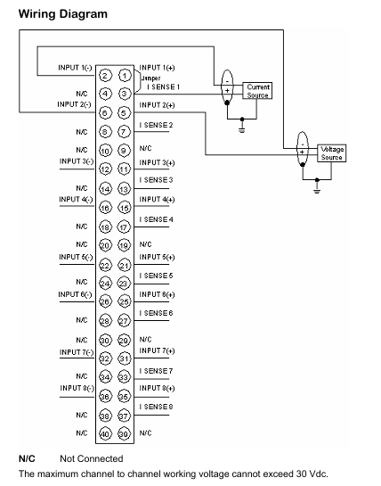
Input channels 1-4, supporting signal input from proximity sensors, speed sensors, and acceleration sensors

Typical power consumption is 7.7 watts

Input impedance standard I/O interface: 10 k Ω (proximity and acceleration input)

Sensitivity (Partial Parameters) – Radial Vibration/Thrust/Eccentricity: 3.94 mV/μ m (100 mV/mil) or 7.87 mV/μ m (200 mV/mil)

-Differential expansion: 0.394 mV/μ m (10 mV/mil) or 0.787 mV/μ m (20 mV/mil)

-Acceleration: 10 mV/(m/s ²) (100 mV/g)

-Speed: 20 mV/(mm/s) pk (500 mV/(in/s) pk) and other specifications

2. Output and status indication

(1) Output interface and parameters

Buffer sensor output with 1 coaxial connector per channel, equipped with short-circuit protection, output impedance of 550 Ω

The recorder outputs a+4~+20 mA current signal (proportional to the monitoring full range), supports independent output for each channel, and short circuits do not affect monitoring operation

Voltage compatibility (current output) 0~+12 Vdc load voltage range, load resistance 0~600 Ω

Axis absolute buffer output, 1 output per channel group, with short-circuit protection, output impedance of 300 Ω

Sensor power supply -24 Vdc

(2) Panel indicator light

OK LED monitor lights up when running normally

When the TX/RX LED monitor communicates with other modules in the 3500 rack, it lights up

When the bypass LED monitor enters bypass mode, it lights up

3. Signal conditioning capability

(1) Frequency response (taking radial vibration as an example)

Direct filter user programmable, single pole -3dB frequency: 4 Hz~4000 Hz or 1 Hz~600 Hz, accuracy ± 1%

Gap filter -3 dB frequency 0.09 Hz

1X/2X vector filter constant Q-value filter, minimum attenuation of stopband -57.7 dB, suitable for mechanical speeds of 60~60000 cpm

Non 1X filter 60 cpm~15.8 times speed, minimum attenuation of stopband -34.9 dB

(2) Measurement accuracy (typical value, 25 ℃ environment)

Radial vibration (direct/clearance/1X/2X) ± 0.33% full-scale (typical value), ± 1% full-scale (maximum value)

Thrust/differential expansion/eccentricity ± 0.33% full-scale (typical value), ± 1% full-scale (maximum value)

Acceleration/velocity ± 0.33% full-scale (typical value), ± 1% full-scale (maximum value, excluding filtering effects)

4. Physical and environmental parameters

(1) Size and weight

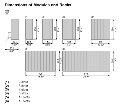
Monitor module (motherboard) 241.3 mm x 24.4 mm x 241.8 mm (9.50 x 0.96 x 9.52 inches) 0.91 kg (2.0 pounds)

I/O module (without isolation switch) 241.3 mm x 24.4 mm x 99.1 mm (9.50 x 0.96 x 3.90 inches) 0.20 kg (0.44 pounds)

I/O module (with isolation switch) 241.3 mm x 24.4 mm x 163.1 mm (9.50 x 0.96 x 6.42 inches) 0.46 kg (1.01 pounds)

(2) Environmental adaptability

Working temperature: 0 ℃~+65 ℃ (32 ℉~+149 ℉)

Storage temperature -40 ℃~+85 ℃ (-40 ℉~+185 ℉)

Relative humidity 20%~80% RH (non condensing)

Protection level module body IP20 (suitable for installation inside the control cabinet)

Core functions and configurations

1. Multi parameter monitoring capability

Support programming each channel through 3500 rack configuration software to achieve the following monitoring functions (channel paired programming, each pair can achieve 2 functions simultaneously):

Radial vibration, thrust position, differential expansion, eccentricity, velocity, acceleration, absolute shaft vibration, circular acceptance region, etc.

2. Alarm and delay settings

Alarm threshold: An “Alert” threshold can be configured for each active static value, and a “Danger” threshold can be configured for any two active static values. The threshold range is 0-100% full scale (limited by the sensor range), and the threshold accuracy is ± 0.13% of the target value.

Alarm delay:

Non axial absolute velocity and REBAM type: warning 1-60 seconds (1-second step), danger 0.1 seconds or 1-60 seconds (0.5-second step);

REBAM type: Both warning and danger are calculated with a minimum value of 400 seconds (warning with a 1-second step and danger with a 0.5-second step).

3. Hazardous Area Certification and Compliance

Electromagnetic compatibility (EMC) complies with the EU EMC Directive 2014/30/EU, EN 61000-6-2 (industrial environment immunity), EN 61000-6-4 (industrial environment emission)

Electrical safety complies with the EU Low Voltage Directive 2014/35/EU, EN 61010-1 standard; UL 60950 certification

Environmental Protection (RoHS) Compliant with EU RoHS Directive 2011/65/EU

Maritime certification ABS (Ship and Marine Applications), DNV GL (Classification of Ships, Marine Equipment, and High Speed Light Ships)

Hazardous Area Certification – CSA/NRTL/C: Class 1, Division 2

-ATEX/IECEx: II 3 G, Ex nA nC ic IIC T4 Gc, etc. (specific I/O modules need to be coordinated)

Ordering and Supporting Information

1. Product model coding rules

3500/42M – AA – BB, among which

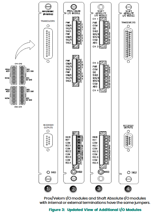
AA (I/O module types): such as 01 (Prox/Seismic I/O module with internal terminal), 04 (4-channel Prox/Accel I/O module with internal isolation switch), etc. (there are a total of 10 options, please refer to the “1/O Module Types” table in the document);

BB (hazardous area certification option): 00 (no certification), 01 (CSA/NRTL/C), 02 (ATEX/IECEx/CSA, only applicable to some AA types).

2. Supporting components

External terminal blocks: such as 125808-02 (European connector proximity terminal block), 128702-01 (European connector recorder terminal block), etc;

Cable: 3500 sensor signal cable (129525 series, length of 5~100 feet optional, including assembled/unassembled options), external terminal block cable (129529 series, with the same specification as the sensor cable);

Spare parts: Monitor body (176449-02), I/O modules (128229-01, 138708-01, etc.), connector splitter (00530843, etc.).

3. Software and hardware requirements

Firmware version: For absolute axis monitoring, 3500/42M firmware version B is required, while REBAM requires 3500/40M firmware version 2.1;

Software version: 3500/01 software 2.50 and above, 3500/02 software 2.20 and above, 3500/03 software 1.21 and above (different functions require higher versions, see document “Firmware&Software Requirements” for details).

Other instructions

Brand affiliation: Bently Nevada is a business under Baker Hughes, and product technical support and document updates can be obtained through Bently.com;

Document version: The data manual version is 143694 Rev. V, released in 2020. Specifications may change without notice, and the actual product shall be subject to the latest document;

Application scenario: Mainly used for monitoring the status of rotating machinery in the fields of power, petrochemicals, intelligent manufacturing, etc., such as preventive maintenance of key equipment such as steam turbine generators, centrifugal compressors, and motors.

GE VMIACC5595 Embedded Industrial Control Module

Product core positioning

VMIAC5595 is an embedded industrial grade control module launched by General Electric (GE), which focuses on high reliability and multi scenario adaptability. Its core is used for signal acquisition, logic control, and equipment linkage in industrial automation systems, especially for industrial scenarios that require compact installation space and stable communication capabilities (such as intelligent manufacturing production lines, industrial equipment monitoring systems, etc.). It is a key component of GE’s embedded control system family.

Key technical specifications

1. Basic hardware parameters

Parameter category specific specifications

The processor configuration is equipped with an industrial grade embedded processor (model not specified in the document, speculated to be a low-power, high stability architecture) to ensure real-time control requirements

Integrated memory and storage standard memory (capacity not specified, suitable for industrial control program operation), supports external storage expansion (such as flash memory module)

Power input wide voltage DC input (typical industrial grade specifications, such as 24V DC, the specific range is not specified in the document, please refer to the actual configuration)

2. Communication and interface capabilities

Core communication protocol: Supports mainstream industrial communication protocols, including Modbus (RTU/TCP), EtherNet/IP (presumably based on GE industrial product conventional configuration), and can achieve seamless data exchange with upper computers, sensors, actuators, and other devices.

Onboard interface:

Digital I/O interface: equipped with multiple sets of discrete input/output ports (quantity not specified, suitable for switch signal acquisition and device control);

Analog interface: supports analog signal input (such as 4-20mA, 0-10V), used for continuous parameter acquisition such as temperature and pressure;

Communication interface: including Ethernet port (RJ45), RS485/RS232 serial port, meeting the requirements of wired network and serial communication;

Expansion interface: Reserve module expansion ports to support the integration of GE’s same series functional modules (such as additional I/O modules and communication modules), enhancing system flexibility.

3. Environmental adaptability

Range of environmental parameter specifications

Working temperature -20 ° C~+60 ° C (industrial grade wide temperature design, suitable for harsh environments such as high and low temperatures in factories)

Storage temperature -40 ° C~+85 ° C (to meet temperature fluctuations during long-term inventory or transportation)

Humidity tolerance 5%~95% RH (non condensing, suitable for high humidity industrial scenarios such as food processing and chemical workshops)

The protection level of the module body shall not be lower than IP20 (suitable for installation inside the control cabinet, preventing dust intrusion)

The anti-interference ability meets the industrial electromagnetic compatibility (EMC) standards (such as EN 61000-6-2/4), and is resistant to electromagnetic radiation and conducted interference

image.png

Software and functional features

Control function: Supports industrial control programming methods such as ladder diagram (LD) and functional block diagram (FBD), which can achieve logic control, timing control, PID closed-loop control (presumably based on the conventional functions of industrial control modules), and meet the requirements of complex industrial processes.

Data processing: It has real-time data collection and local caching capabilities, and can preprocess the collected sensor data (such as filtering and range conversion) to reduce the pressure of data processing on the upper computer.

Diagnosis and maintenance: Integrated self diagnostic function can monitor the hardware status of modules (such as power, communication, I/O ports), and provide fault information through indicator lights or communication protocols for quick troubleshooting.

Certification and Compliance

International safety certification: Complies with CE certification (EU safety and electromagnetic compatibility standards), UL certification (US safety standards), and some configurations may have IECEx explosion-proof certification (suitable for hazardous industrial environments, subject to specific models).

Industry standard adaptation: Follow relevant standards in the field of industrial automation (such as IEC 61131-3 programmable controller standard) to ensure compatibility with other industrial equipment.

image.png

Rockwell SLC ™  500 series 1747-L543 (SLC 5/04 controller)

Product core positioning

1747-L543 is Rockwell Automation (Allen Bradley) ®) SLC ™  The SLC 5/04 compact programmable logic controller (PLC) under the 500 series, with a core configuration of 64K memory and integrated RS232 and DH+communication functions, is mainly used for logic control and equipment linkage in industrial automation scenarios. It belongs to the category of modular programmable controllers and supports flexible system expansion and upgrading.

Key technical specifications

1. Basic and Storage Parameters

Parameter category specific specifications

Product series SLC (corresponding to manual numbers 1746/1747)

Component type PLC controller (belonging to Compact PLC Systems)

Controller memory 64 kB

The memory card option supports Compact Flash expansion

2. Communication capability

Communication protocol: Supports DeviceNet Remote IO protocol to meet the networking requirements of industrial grade devices.

Onboard communication port: Integrated with DH-485 and RS232 ports, it can directly connect devices corresponding to communication standards without the need for additional modules.

3. I/O expansion capability

Maximum Analog I/O: Supports up to 480 points, meeting the acquisition and control requirements of continuous signals such as temperature and pressure.

Maximum digital I/O: Supports up to 8192 points and can connect a large number of discrete devices such as switches, sensors, and actuators, adapting to complex industrial scenarios.

4. Environmental adaptability

Range of environmental parameter specifications

Working temperature (minimum) 0 ° C

Working temperature (maximum) 60 ° C

Storage temperature (minimum) -40 ° C

Storage temperature (maximum) 85 ° C

Maximum relative humidity of 95% RH (no mention of condensation, presumed to be an industry standard non condensing environment)

Supporting and Supporting Services

Peripheral accessory supply: We provide a full range of replacement and expansion parts, including power supplies, chassis, communication modules, I/O cards, and various accessories, to facilitate system maintenance and upgrades.

Communication upgrade option: Can be paired with 1747-AENTR Ethernet I/P adapter to upgrade the existing system to a distributed I/O architecture, enhancing network flexibility and coverage.

Technical support guarantee: NHP and Rockwell Automation provide continuous support, including lifecycle management strategies, to help users plan equipment updates and long-term use.

Certification and reference materials

Compliance certification: Possess IECEx certification (International Electrotechnical Commission Explosion proof Certification), comply with the Supplier Declaration of Conformity, and meet industrial safety and compliance requirements.

Reference documents: Provide installation guide, user manual, manufacturer datasheet, and product selection catalog for users to install, operate, and select.

Installation precautions

First, the importance of industrial equipment installation

In modern industrial production, various equipment and machines are widely used in various fields, such as manufacturing, energy industry, chemical industry and so on. The installation of industrial equipment is directly related to production efficiency and product quality. Proper installation and commissioning of good equipment can ensure the stable operation of the production line, improve production efficiency and product quality, reduce maintenance costs, and ensure the safety of employees.

image.png

Second, the steps of industrial equipment installation

1. Preparation: Before the installation of industrial equipment, it is necessary to carry out adequate preparation work. This includes the tools and equipment required for installation, cleaning and preparation of the installation site, and making installation plans and schedules.

2. Determine the installation position: Determine the installation position of the equipment according to the requirements of the equipment and the layout of the production line. When determining the location, the weight and size of the equipment need to be considered, as well as the coordination of the equipment with the surrounding environment.

3. Install the device: Assemble and install the device according to the installation instructions. Ensure that the device is securely and accurately connected, while protecting the appearance and internal components of the device.

4. Connect power supplies and pipelines: For devices that require power supplies and power supplies, properly connect power supplies and pipelines. The connection of power supply and pipeline should comply with safety standards to avoid hazards such as electric shock and leakage.

5. Commissioning the device: After the installation is complete, you need to commission the device to ensure that the device can run properly. It includes checking the functions and performance of the equipment, adjusting the parameters and Settings of the equipment, and carrying out the necessary tests and inspections.

6. Training operators: After the installation of the equipment, it is necessary to train the operators to understand the operation methods and precautions of the equipment, and improve the operation skills and safety awareness of the employees.

Third, industrial equipment installation precautions

1. Safety first: When installing industrial equipment, safety is the most important consideration. You must operate in strict accordance with safety regulations and wear necessary protective equipment to ensure the safety of the workplace.

2. Strictly follow the equipment instructions: Industrial equipment usually comes with detailed installation instructions, you must carefully read and understand the contents of the instructions, and install the operation in accordance with the requirements of the instructions.

3. Pay attention to the assembly sequence: When installing the device, follow the correct assembly sequence to ensure that all components of the device are assembled correctly to avoid equipment failures or safety accidents caused by incorrect assembly sequence.

Applicable Industries

petroleum

Natural gas

chemical industry

cement

metallurgy

ship

mining industry

aviation

transport

Alcoa

machinery

manufacturing

car

image.png

Honeywell WEB-HMI10/CF 10.1 “TFT ARM Cortex-A53 Quad Core

Product core positioning

WEB-HMI10/CF is a 10.1-inch HTML5 web human-machine interface (HMI) product under Honeywell’s CentraLine series, featuring industrial grade high reliability and advanced connectivity, suitable for building automation, infrastructure automation, and OEM scenarios. It can provide a cost-effective solution for HMI applications in factories and building automation, with a design life of over 10 years.

Key hardware and display configuration

1. Display and Touch Control

Screen specifications: 10.1-inch TFT color display screen, 16:10 ratio, resolution 1280 × 800 (WXGA), supports 16 million colors, typical brightness value of 500 Cd/m ², and can achieve 0% dimming (LED backlight).

Touch technology: Pure glass projected capacitive touch screen, supporting multi touch, with scratch resistance, UV resistance, and chemical corrosion resistance, smooth and durable operation.

2. Core performance

Processor: i.MX8M Mini quad core ARM Cortex-A53, ensuring smooth operation.

Storage and Memory: 2GB RAM+4GB Flash, meeting the program running and data storage requirements in industrial scenarios.

Additional features: Equipped with real-time clock (RTC) and backup battery (non replaceable by the user), buzzer, to enhance user convenience.

3. Interface configuration

Quantity and specification description of interface types

Three Ethernet ports (ports 0:10/100/1000Mb; ports 1-2:10/100Mb) support high-speed network connections and meet the communication needs of multiple devices

Two USB ports (USB 2.0 host mode, maximum 500mA) can be used to connect external devices such as mice, USB drives, etc

0 serial ports are not supported for serial connection

0 SD card slots do not support SD card expansion

Expansion slot 0 without plugin module extension function

image.png

Environment and installation parameters

1. Environmental adaptability

Working temperature: -20 ° C~+60 ° C (vertical installation), if connected to a USB device, the maximum temperature limit is+50 ° C.

Storage temperature: -20 ° C~+70 ° C.

Humidity: 5%~85% RH (non condensing), suitable for various humidity environments.

Protection level: IP66 on the front (dustproof and waterproof), IP20 on the back (dustproof), suitable for installation in industrial control cabinets.

2. Size and weight

Panel size (length x height): 282mm x 197mm (11.10 inches x 7.76 inches).

Hole size (length x height): 271mm x 186mm (10.67 inches x 7.32 inches), suitable for standard control cabinet openings.

Depth: 52mm (main body)+8-8.5mm (protruding part), total depth 2.05 inches+0.31-0.33 inches.

Weight: 2.5kg, strong installation stability.

Software and Security Features

Operating System: Based on Linux system, ensuring system stability and security.

Browser: Equipped with modern HTML5 Chromium browser, it can access CentraLine WebServer or ARENA NX applications, supporting web-based control and data viewing.

Network security: With a high level of network security, it can prevent unauthorized access and protect device and data security.

Certification and Compliance

CE certification: Compliant with EN 61000-6-4 (radiation) and EN 61000-6-2 (immunity) standards, suitable for installation in industrial environments.

UL certification: Complies with UL 61010-1 (3rd edition) and UL 61010-2-201 (1st edition) standards, and meets international safety regulations.

Order Information

WEB-HMI10/CF 10.1-inch HTML5 web panel (capacitive touch) 10.1-inch TFT color screen (1280 × 800 pixels), capacitive multi touch, 3 Ethernet ports, 2 USB host ports

image.png

Rockwell Automation 1756 Series ControlNet Communication

Product Family and Core Positioning

1. Model classification and functional differences

The 1756 series ControlNet module is divided into “media type”, “corrosion resistance”, and “temperature adaptation range” to meet the needs of different industrial scenarios. The specific model functions are as follows:

Model Core Features Applicable Scenarios

1756-CN2 standard media (non redundant), conventional industrial environment without anti-corrosion coating, single network link

1756-CN2K standard media (non redundant), with anti-corrosion coating (model ending with “K” mark), corrosive industrial environment (such as chemical and metallurgical)

1756-CN2R redundant media (dual link A/B), high reliability demand scenario without anti-corrosion coating (such as energy, transportation)

1756-CN2RK redundant media (dual link A/B) with anti-corrosion coating and high reliability requirements scenario

1756-CN2RXT redundant media, wide temperature design (-25~70 ℃), without anti-corrosion coating for extreme temperature environments (such as outdoor and refrigerated)

2. Core advantages of ControlNet network

The ControlNet network connected to the module combines I/O network and Peer to Peer network functions, with the core features of:

Deterministic communication: ensuring repeatable and low latency transmission of critical control data;

Support redundancy: Redundant models (CN2R/CN2RK/CN2RXT) achieve network fault redundancy switching through dual links (A/B) to improve system stability.

image.png

Environmental requirements and safety certification

1. Basic environmental standards

Pollution level: only applicable to industrial environments with pollution level 2 (defined by IEC/EN 60664-1, which means the air contains only a small amount of non-conductive dust);

Overvoltage category: Class II application (IEC/EN 60664-1), suitable for downstream equipment in industrial distribution systems;

Altitude: up to 2000 meters (6562 feet), no need to downgrade for use;

Installation form: Open device, to be installed in an enclosure that meets the following requirements:

Protection level: at least IP54 (EN/IEC 60529);

Flame retardant rating: Non metallic shells must meet a 5VA flame spread rating;

Operation restriction: Tools are required to open the inside of the casing to prevent personnel from coming into contact with live parts.

2. Hazardous Area Certification

The module has been certified for hazardous areas in multiple regions, and the requirements for different regions are as follows:

Core requirements for certification areas

North America (Class I, Div 2) is suitable for A/B/C/D hazardous areas (such as environments containing flammable gases), with a temperature code of T4;

It is strictly prohibited to plug in or unplug modules/wiring in non power off or unknown non hazardous areas;

Components cannot be replaced, otherwise they may compromise their suitability for hazardous locations.

ATEX/UKEX equipment group II, category 3, protection type “Ex ec IIC T4 Gc” (increased safety type);

Only applicable to Zone 2 hazardous areas (where explosive gas environments rarely occur or occur in the short term);

It needs to be used with a UKEX/ATEX certified casing (IP54 or above).

IECEx certification protection type is the same as ATEX (Ex ec IIC T4 Gc), suitable for Zone 2 hazardous areas;

Transient protection must be met (peak voltage at the power supply end ≤ 140% of the rated value).

3. Requirements for electrostatic protection

The module is sensitive to static electricity, and the following should be followed during operation:

Contact with grounded objects to release static electricity, or wear a grounded wristband;

Do not touch module connectors, pins, and internal circuits;

When not in use, it should be stored in anti-static packaging;

Prioritize using anti-static workbenches.

Installation and wiring operations

1. Preparation before module installation

Slot position: Supports any size of ControlLogix chassis and can be installed in any slot (ensuring sufficient power capacity);

Redundant system requirements: The primary/backup modules need to be installed in the same slot of the corresponding chassis (such as the primary module in slot 3, and the backup module also needs to be in slot 3 of the backup chassis).

Network address setting:

Address range: Independent chassis modules range from 01 to 99, redundant chassis modules range from 01 to 98 (00 is an invalid address, only used for resetting);

Setting method: Adjust through the two digit dip switch on the side of the module (ten digits on the left and one digit on the right), ensuring that the address is unique within the same network.

2. Module installation and disassembly steps

(1) Installation steps

Confirm that the power supply of the chassis has been disconnected (power must be cut off in hazardous areas, and normal environments can support live plugging, but it is not recommended);

Align the module circuit board with the upper and lower rails of the chassis, and smoothly push it into the backplane connector;

Confirm that the module is flush with the power/other modules and not loose (do not forcefully press to avoid damaging the connector).

(2) Disassembly steps

Press the upper/lower tabs on both sides of the module to unlock it;

Smoothly slide the module out of the chassis, and power off in hazardous areas first.

3. ControlNet network wiring (Tap connection)

The module needs to be connected to the network through a ControlNet tap (Tap, such as 1786-TPR/TPS/TPYR/TPYS/TCT2BD1), with the following specific requirements:

Media type wiring method

Non redundant (CN2/CN2K) only connects the tap to module A channel (B channel is not used), and the tap needs to be selected as a direct connection type (such as 1786-TPS) to adapt to the BNC interface at the bottom of the module

Redundant (CN2R/CN2RK/CN2RXT) tap A is connected to module A channel, and tap B is connected to module B channel; Dual links need to be simultaneously connected to the network backbone (Trunk Line A/B)

Key wiring precautions:

Unused ports (such as the B channel of CN2) need to retain protective plugs (pre installed with the “K” model) to ensure the anti-corrosion level;

When the tap changer is disconnected from the module, it is necessary to immediately cover it with a dust cap to prevent the metal part from contacting the grounding surface;

In a redundant system, the main/backup modules need to be connected to the same network segment (such as the main module A channel connected to Trunk A, and the backup module A channel also needs to be connected to Trunk A).

4. USB port usage specifications

The module is equipped with a USB 2.0 Type B port, which is only used for temporary local programming. Core limitations:

Prohibited from use in hazardous areas;

Cable length ≤ 3 meters (9.84 feet), cannot be connected to a USB hub;

RSLinx Classic 2.55 and above software must be installed;

It is prohibited to upgrade multiple module firmware through USB at the same time to avoid upgrade failure.

image.png

Module reset and troubleshooting

1. Restore factory settings (reset operation)

When a module needs to clear configuration or fix exceptions, the following steps can be performed:

Disconnect the power supply of the chassis and remove the module;

Set the dip switch to “00” (invalid address, only used for reset);

Reinstall the module and connect the power supply;

After the module displays “Reset Complete Change Switch Settings”, disconnect the power and remove the module;

Return the dip switch to the target address (01~99/98), reinstall and power on.

2. Core methods for troubleshooting

By using the OK status indicator light and network channel indicator light (A/B) of the module to locate the fault, the key status interpretation is as follows:

(1) OK status indicator light (core fault diagnosis)

Reason and solution for malfunction of indicator light status display information

Turn off power failure or internal failure: Check the power connection and module for tightness. If it is ineffective, replace the module

Reset Complete Change Switch Settings address to 00 (invalid): Reset valid address (01~99/98)

Frequent red FAIL power on test failure: replace module directly

Flashing red DUPLICATE NOTE DETECTED Network address conflict: Replace with unique address

Flashing red Image update Needed firmware needs to be updated: Use ControlFLASH software to upgrade Boot image

Evergreen/Blinking Green CPU=xx% (xx ≥ 80) CPU utilization is too high (over 80%): Check the number of network connections and optimize the control program

Blinking green NET ERR network wiring error or no other nodes: Check cables, terminators, and ensure that at least one other node is online

(2) Network channel indicator light (A/B channel status)

Interpretation of indicator light status channel (A/B) status

Evergreen is operating normally, and channel communication is functioning properly

Flashing green/extinguishing temporary error, module can self recover

Flashing red/off media malfunction (such as disconnection, looseness) or no other nodes: Check cables, terminators, and add online nodes

Constant red channel fault: power off reset module, if ineffective, contact Rockwell technical support

Key technical parameters

Parameter category 1756-CN2/CN2K 1756-CN2R/CN2RK 1756-CN2RXT

Backboard current 1.1A (5.1V DC) 1.3A (5.1V DC) 1.3A (5.1V DC)

Working temperature: 0~60 ℃ (32~140 ℉) 0~60 ℃ (32~140 ℉) -25~70 ℃ (-13~158 ℉)

Isolation voltage 30V DC (continuous), basic insulation between ControlNet/USB and backplane (500V AC withstand voltage for 60 seconds) on the same left (redundant models additionally support A/B channel isolation) on the same left

Anti corrosion grade (with “K”) ASTM B845-97 G3 grade (ANSI/ISA 71.04), IEC 60721-3-3 CX grade same as left

The wiring category for ControlNet ports is Class 1, and for USB ports it is Class 3. Same as left

NI 6030E/6031E/6032E/6033E series

The official specification book for National Instruments 6030E series data acquisition equipment, covers four core models of PCI/PXI bus types (NI 6030E/6031E/6032E/6033E), detailing the technical parameters of the device’s I/O terminal definition, analog input/output, digital I/O, counter/timer and other core functions, as well as physical specifications, environmental adaptability and certification information. It is suitable for industrial data acquisition, laboratory measurement and other scenarios. The specific content is as follows:

Product Family and Basic Positioning

1. Model classification and bus type

The 6030E series equipment is divided according to “channel quantity” and “bus interface”, covering different acquisition scale requirements. The specific models are as follows:

NI 6030E PCI/PXI 16 channel single ended/8-channel differential (only supports analog input/output)

NI PCI-MIO-16XE-10 PCI, like NI 6030E, is a version of the 6030E series PCI

NI 6031E PCI/PXI 64 channel single ended/32 channel differential (supports analog input/output)

NI 6032E PCI 16 channel single ended/8-channel differential (only supports analog input)

NI 6033E PCI 64 channel single ended/32 channel differential (only supports analog input)

2. Core functional framework

All models integrate three core functions: analog input (AI), digital I/O (DIO), and counter/timer. Some models (6030E/6031E) additionally support analog output (AO), and uniformly support DMA data transfer (scattering aggregation mode), programmable triggering and calibration functions, adapting to high reliability data acquisition requirements.

Core technical parameters

1. Analog Input (AI): Core Features of the Entire Series

(1) Basic collection ability

Number of channels: 6030E/6032E are 16 single ended/8-differential channels (configurable by software), 6031E/6033E are 64 single ended/32 differential channels;

ADC type: Successful Approximation, resolution 16 bits (1/65536);

Maximum sampling rate: 100 kS/s for a single channel (refer to the established schedule for multi-channel rates);

Input range: The software can configure bipolar (± 10V~± 100mV) and unipolar (0~10V~0~100mV), with a total of 12 ranges, supporting DC coupling;

Overvoltage protection: ± 25V when powered on, ± 15V when powered off, input voltage must be kept within ± 11V of ground.

(2) Accuracy and stability

Absolute accuracy: Taking the ± 10V range as an example, the full-scale absolute accuracy of the average data (100 points) after one year is 1.147mV (calibrated at 25 ℃ environment);

Temperature drift: Misalignment temperature drift ± 5 μ V/℃, gain temperature drift ± 8ppm/℃;

Common mode rejection ratio (CMRR): At DC~60Hz frequency, the small range (100mV~500mV) can reach 105dB, and the large range (± 10V) can reach 97dB, with strong anti-interference ability.

(3) Buffer and transmission

FIFO cache: 1024 samples for 6031E OEM version, 512 samples for other models;

Data transfer: Supports 3-channel DMA (analog input/output, counter 0/1), compatible with interrupts and programmable I/O.

2. Analog output (AO): only supported by 6030E/6031E

Number of channels: 2 channels (AO 0/AO 1), DAC with dual buffer design;

Output range: The software can be configured with ± 10V (bipolar) and 0-10V (unipolar);

Drive capability: ± 5mA current drive, output impedance of 0.1 Ω, supporting ground short circuit protection;

Dynamic performance: establishment time of 10 μ s (± 1LSB accuracy), slew rate of 5V/μ s, noise of 60 μ V rms (DC~1MHz);

Cache and transfer: FIFO cache 2048 samples, supporting DMA scatter aggregate transfer.

3. Digital I/O (DIO): Unified specifications for the entire series

Channel configuration: 8 universal digital channels (P0<0~7>), supporting bidirectional switching of input/output;

Logic level: compatible with 5V TTL/CMOS, input low level 0~0.8V, high level 2.0~5.0V; output low level ≤ 0.4V (24mA current), high level ≥ 4.35V (13mA current);

Trigger and Control: 10 programmable functional interfaces (PFI<0~9>), configurable for analog trigger (start/reference), counter source/gate control, supporting ± 35V overvoltage protection (when disabled).

4. Counter/Timer: Unified specifications for the entire series

Configuration: 2 24 bit up and down counters, 1 4-bit frequency divider;

Reference clock: The counter supports 20MHz/100kHz, the frequency divider supports 10MHz/100kHz, and the clock accuracy is ± 0.01%;

External frequency: maximum external source frequency of 20MHz, minimum pulse width of 10ns (edge detection mode);

Function support: frequency measurement, pulse width measurement, pulse generation, support for external source/gate selection (PFI/RTSI trigger line).

Definition and physical specifications of I/O terminals

1. Terminal interface

Connector types: 6030E/6032E are 68 pin male SCSI-II type, 6031E/6033E are 100 pin female 0.05 D type;

Key terminal functions:

Analog signals: AI<0~63>(6031E/6033E), AI SENSE (2-channel, 6031E/6033E), AO 0/AO 1, AI GND/AO GND;

Digital signal: P0<0~7>, PFI<0~9>, CTR 0/1 OUT, FREQ OUT;

Power supply:+5V (1A output, for external circuits), D GND (digital ground).

2. Physical and environmental parameters

Size: PCI device 17.5cm × 10.6cm (6.9in × 4.2in), PXI device 16.0cm × 10.0cm (6.3in × 3.9in);

Weight: 179-199g (6.2-7.0oz), slightly different due to model differences;

Working environment: temperature 0~50 ℃, humidity 10%~90% (no condensation), altitude ≤ 2000m;

Storage environment: Temperature -20~70 ℃, humidity the same as the working environment.

Calibration and Certification

1. Calibration requirements

Preheating time: Recommended 15 minutes (to ensure stable accuracy);

Calibration cycle: 1 year, supporting internal calibration (relying on onboard 5.000V reference source, temperature drift ± 0.6ppm/℃) and external calibration (reference voltage 6-9.999V);

Calibration storage: Calibration parameters are stored in EEPROM to ensure accuracy is maintained after power failure.

2. Compliance certification

Safety standards: comply with IEC 61010-1, EN 61010-1, UL 61010-1, CAN/CSA-C22.2 No. 61010-1;

Electromagnetic compatibility (EMC):

Radiation: EN 55011 Class A (10m), FCC Part 15A (>1GHz);

Immunity: EN 61326:1997 A2:2001;

Regional certification: CE, C-Tick, FCC Part 15 (Class A), requiring the use of shielded cables to ensure EMC compliance.

Additional design details

Trigger function: Supports analog triggering (12 bit resolution, programmable hysteresis) and digital triggering. The trigger source can be selected from AI channel, PFI interface, or RTSI trigger line (7 PCI devices, PXI devices compatible with PXI trigger bus);

Power requirements: The I/O connector provides+4.65~+5.25V DC (1A), and the bus power supply needs to refer to the specific equipment manual (excluding external VCC power consumption);

Pin definition: The document contains detailed pin diagrams for four models (such as the 68 pin pin of 6030E and the 100 pin pin of 6031E), clarifying the signal types and grounding relationships of each terminal for easy wiring deployment.

ABB 1TGE120011R1000 motor and feeder control unit

Product core positioning and basic information

Product Name: MControl Motor&Feeder Control Unit

Adaptation System MNS iS (Low Voltage Motor Control Center Related Systems, Belonging to the IEC Low Voltage Product Category)

Product type: Standard type MControl(Extended Product Type:MControl;Long Description:MControl (Standard))

Product ID/Model 1TGE120011R1000

Product Classification: Low Voltage Products and Systems – Low Voltage Systems – IEC Low Voltage Motor Control Centers – MNS iS

WEEE (Electronic Waste) is not within the scope of WEEE control (Product Not in WEEE Scope)

Physical specifications and weight

The control unit is compact in size, lightweight, and suitable for the spatial installation requirements of industrial equipment

Product net width: 53mm

Product net height: 125mm

Product net depth/length: 260mm

Net weight of product: 0.7kg

Compliance certification

CE conformity declaration: The corresponding document number is “1TGE097001”, indicating that the product complies with the relevant standards of the EU CE certification and can be used in compliance with the EU and regions that recognize the CE mark.

First, the importance of industrial equipment installation

In modern industrial production, various equipment and machines are widely used in various fields, such as manufacturing, energy industry, chemical industry and so on. The installation of industrial equipment is directly related to production efficiency and product quality. Proper installation and commissioning of good equipment can ensure the stable operation of the production line, improve production efficiency and product quality, reduce maintenance costs, and ensure the safety of employees.

Second, the steps of industrial equipment installation

1. Preparation: Before the installation of industrial equipment, it is necessary to carry out adequate preparation work. This includes the tools and equipment required for installation, cleaning and preparation of the installation site, and making installation plans and schedules.

2. Determine the installation position: Determine the installation position of the equipment according to the requirements of the equipment and the layout of the production line. When determining the location, the weight and size of the equipment need to be considered, as well as the coordination of the equipment with the surrounding environment.

3. Install the device: Assemble and install the device according to the installation instructions. Ensure that the device is securely and accurately connected, while protecting the appearance and internal components of the device.

4. Connect power supplies and pipelines: For devices that require power supplies and power supplies, properly connect power supplies and pipelines. The connection of power supply and pipeline should comply with safety standards to avoid hazards such as electric shock and leakage.

5. Commissioning the device: After the installation is complete, you need to commission the device to ensure that the device can run properly. It includes checking the functions and performance of the equipment, adjusting the parameters and Settings of the equipment, and carrying out the necessary tests and inspections.

6. Training operators: After the installation of the equipment, it is necessary to train the operators to understand the operation methods and precautions of the equipment, and improve the operation skills and safety awareness of the employees.

Third, industrial equipment installation precautions

1. Safety first: When installing industrial equipment, safety is the most important consideration. You must operate in strict accordance with safety regulations and wear necessary protective equipment to ensure the safety of the workplace.

2. Strictly follow the equipment instructions: Industrial equipment usually comes with detailed installation instructions, you must carefully read and understand the contents of the instructions, and install the operation in accordance with the requirements of the instructions.

3. Pay attention to the assembly sequence: When installing the device, follow the correct assembly sequence to ensure that all components of the device are assembled correctly to avoid equipment failures or safety accidents caused by incorrect assembly sequence.

Watlow CLS200 series controller

Core positioning and overall advantages of the product

The CLS200 series controller is designed with a compact 1/8 DIN package, which enables precise control of multiple circuits in a limited space. Its core advantages are concentrated in three dimensions: “efficiency, flexibility, and ease of operation”

Space and efficiency optimization: A single device supports PID control for up to 16 heating/cooling circuits, significantly reducing the panel space occupied by a single circuit, while reducing the number of installed components, lowering the probability of failure, and shortening installation time;

Simplified operation: It has menu guided operation+full-text display, supports storage and calling of 8 job programs, can quickly switch production processes, and the “Auto tune” function reduces the professional threshold for parameter settings;

Strong compatibility: Supports thermocouples RTD、 Multiple sensor inputs such as linear DC voltage/current reduce user learning costs and spare parts inventory; Built in EIA/TIA-232/485 serial communication interface, seamlessly integrated with PLC and upper computer software (such as WATVIEW).

This series of controllers is approved by UL ®、 C-UL ®  Certified to comply with the EU EMC Directive and bear the CE mark, suitable for multi loop control scenarios in the field of industrial automation (such as plastic extrusion, mass production, etc.).

Differences in Model Classification and Core Functions

The CLS200 series is divided into core models according to the “number of circuits”, and there are clear differences in input types and channel quantities among different models. At the same time, the “firmware options” can be used to expand functions to meet different application needs:

1. Classification of basic models (by number of circuits/channels)

Model Channel Quantity Input Type Core Adaptation Scenario

CLS204 4 differential input small multi loop control (such as 4-channel temperature control)

CLS208 8 differential input medium-sized multi loop control, supporting RTD input

CLS216 16 single ended input large multi loop centralized control

2. Firmware function options (select as needed)

Different firmware versions determine the core algorithms and functional range of the controller, covering requirements from basic temperature control to complex process control

Standard firmware: Basic closed-loop PID control, automatic tuning, fault sensor detection, alarm function, job storage;

Extruder specific firmware: Based on standard functions, optimize PID control logic for plastic extrusion process;

Ramp and Soak firmware: Added “ramp heating+constant temperature maintenance” function and process variable retransmission (requires SDAC module), supports complex batch processing;

Enhanced firmware: includes standard features, with additional support for cascade control, proportional control, differential control, and remote simulation set points. Each channel can flexibly configure control algorithms (note: cascade control/remote set points require 2 controller channels).

Key technical parameters

1. Human computer interaction and configuration

Display and operation: 32 character vacuum fluorescent display screen, 8-key keyboard (used for menu access, password verification, parameter settings, channel switching);

Configuration method: Controller parameters can be loaded through standard serial ports, supporting single channel/multi-channel display switching.

2. Input performance (sensors and signals)

(1) Input type and precision

Supporting multiple sensor inputs, the measurement range and accuracy of different types are shown in the table below:

Input type, specific specifications, accuracy (@ 25 ℃ environment)

Thermocouples support B/E/J/K/R/S/T types, including cold end compensation and reverse/short circuit detection; Type B has a range of 66-1760 ℃, Type K has a range of 268-1371 ℃ ± 1.0~4.0 ℃ (depending on the type, Type B has the lowest accuracy)

RTD is only supported by CLS204/CLS208, with 2/3 wire platinum resistance (100 Ω @ 0 ℃), divided into 2 ranges:

– RTD1:-100-275℃

– RTD2:-120-840℃ RTD1:±1.1℃; RTD2:±1.6℃

Linear signal supports 0-10mA/4-20mA DC current, 0-100mV/0-5V/0-10V/0-12V DC voltage (requires external scaling resistor)-

Pulse signal TTL level square wave, maximum frequency 2kHz-

(2) Input sampling and anti-interference

Sampling rate: CLS204 (6 times/second, update time 0.167 seconds), CLS208 (3 times/second, 0.333 seconds), CLS216 (1.5 times/second, 0.667 seconds);

Anti interference capability: noise suppression ratio of 120dB at a frequency of 60Hz, temperature coefficient of 40ppm/℃;

Measurement resolution:>14 bits, internal measurement accuracy 0.006%.

3. Output performance

Digital output: The number of outputs varies depending on the terminal board options – the 50 pin terminal board supports 34 digital outputs, while the 18 pin terminal board supports 10 control outputs; Each output can be configured as “switch time proportional control” or “distributed zero crossing (DZC) control”, with a maximum single current of 60mA (5V DC), and the onboard power supply can provide 350mA (5V DC);

Alarm output: Each channel is independently configured with “process alarm” and “deviation alarm”, supporting programmable dead zone, delay, and start suppression. The global alarm output can summarize the alarm status of all channels, and there is also a “watchdog output” to indicate that the controller is running normally.

4. Communication and Power Supply

Serial communication: Supports EIA/TIA-232 or EIA/TIA-485 (selectable via jumper), baud rates can be selected as 2400/9600/19200, protocol compatible with ANSI X3.28-1976 (D1, F1) and Allen Bradley PLC/2, Modbus ®  RTU;

Power requirements: 15-24V DC (± 3V DC), maximum current 1A, current 300mA without load; optional 120/240V AC (50/60Hz) power adapter (output 15V) DC@1.2A , UL ®  Class 2 certification).

5. Environmental adaptability

Working temperature: not clearly indicated (reference to general industrial equipment standards, estimated to be -10~55 ℃, subject to actual application);

Anti interference: Complies with industrial grade electromagnetic compatibility requirements (relying on the EMC testing standards corresponding to CE certification).

Optional accessories and software

1. Analog Conversion Module (DAC/SDC)

The CLS200 series has no onboard analog output and requires external modules to achieve analog signal conversion:

DAC module: converts the DZC output signals of 1-2 controllers into analog signals, and the output types can be configured on-site as 4-20mA DC, 0-5V DC, or 0-10V DC;

SDAC module (serial digital to analog converter): converts 1 controller output into high-precision analog voltage/current signals, suitable for scenarios such as process variable retransmission, open-loop control, motor speed control, etc., with CE, UL ®、 C-UL ®  authentication.

2. Upper computer software (WATVIEW)

Optional Windows ®- Based HMI software, core functions include:

Simultaneously monitor/configure up to 32 CLS200 controllers;

Support parameter settings, custom recipe management, alarm monitoring, trend chart drawing, real-time data recording, and export log data to a spreadsheet;

Divided into “Run time” and “Developer” versions, the Developer version additionally supports custom interface design and has higher configuration efficiency than general HMI software.

Order information and attachments

1. Core ordering code rules

The CLS200 series order requires clear parameters such as “number of channels, controller type, terminal board, power supply, communication accessories, and special inputs”. The core code meanings are as follows:

Description of optional parameters for code snippets

Channel number 04=4 channels (CLS204), 08=8 channels (CLS208), 16=16 channels (CLS216)

Controller type 1=standard firmware, 2=extruder firmware, 3=ramp constant temperature firmware, 4=enhanced function firmware

Terminal board 0=SCSI interface only (user provided cable), 1=18 pin terminal board (CLS204/208 only), 2=50 pin terminal board (including 3-foot SCSI cable)

Power adapter 0=none, 3=120/240V AC to 15V DC (1.2A)

Serial communication configuration communication cable (0=none, 1=10 feet DB-9 cable, etc.), communication protocol (0=232, 1=485, 2=485 terminal matching)

Special input 0/00=thermocouple only+(-10~60mV), X/XX=custom current/voltage/RTD input (input type and channel range need to be specified)

2. Other attachments

Software keys: WATVIEW runtime version (WV00-R0U0-000=USB key, WV00-R0P0-000=parallel key), development version (WV00-D0U0-000=USB key, etc.);

DAC/SDC power supply: B=120V AC to 16V DC (300mA, for 10 DACs), H=120/240V AC to 15V DC (1.2A, for 12 DACs), L=120/240V AC to 5V DC (3A, for 10 SDACs).

Schneider 140DDI84100 Discrete Input Module

Core product positioning and basic parameters

This module belongs to the DC discrete input module of Modicon Quantum automation platform, with the following core basic parameters:

Discrete input quantity: 16

Channel grouping: 8 channels per group

Input logic type: Positive (sink)

Address requirement: occupies 1 input word

Module Form: Standard Format

Product weight: 0.3kg

Certification mark: Compliant with CE certification

Electrical performance indicators

1. Input voltage and current

Input voltage range: 10-60V DC, with different current requirements for different voltages:

12V DC:5-10mA

24V DC:6-30mA

48V DC:2-15mA

60V DC:1-5mA

Voltage state threshold (guaranteed value):

State 1 (high level): 9-12V at 12V ± 5%, 11-24V at 24V ± 20%, 34-48V at 48V ± 20%, 45-60V at 60V ± 20%

State 0 (low level): 0-1.8V at 12V ± 5%, 0-5V at 24V ± 20%, 0-10V at 48V ± 20%, 0-9V at 60V ± 20%

Absolute maximum voltage: 75V DC

2. Response and switch performance

Response time: both state 0 → 1 and state 1 → 0 are 4ms

Switching frequency: ≤ 100Hz

3. Isolation and power consumption

Isolation performance: 2500Vrms DC (continuous for 1 minute) is isolated between channel groups and buses, and 700Vrms DC (continuous for 1 minute) is isolated between channel groups

Power consumption: 1W+(0.62 x activated points)

Bus current requirement: 200mA

Signal indication and anti-interference capability

1. Local signal indication (LED)

Green LED (Active): indicates normal bus communication

Red LED (F): Indicates detection of external fault

16 green LEDs: corresponding to the status of 16 input points (displaying whether the input is valid)

2. Anti interference standards

Electrostatic discharge resistance: Contact discharge 4kV, air discharge 8kV (compliant with IEC 801-2 standard)

Electromagnetic field resistance: 10V/m (frequency 80-2000MHz, in accordance with IEC 801-3 standard)

Environmental and Certification Requirements

1. Environmental adaptation range

Working environment temperature: 0-60 ° C

Storage environment temperature: -40-85 ° C

Relative humidity: 95% (without condensation)

Working altitude: ≤ 5000m

2. Product certification standards

Following standards: CSA C22.2 No 142, UL 508

Product certification: C-Tick certification, FM Class 1 Division 2 certification

Sustainability and environmental attributes

Sustainable Supply Status: Belongs to “Green Premium Products” (Schneider Green Preferred Products)

RoHS Compliance: Compliant with RoHS standards since January 2009, with Schneider Electric Declaration of Conformity

Product environment file: obtainable

Scrap disposal: No special recycling operation is required, simplifying the subsequent environmental treatment process

Modicon Quantum 140ACI03000 Analog Input Module

Product Core Information and Positioning

1. Basic positioning

Platform: Modicon Quantum Automation Platform.

Product type: 8-channel multi range differential analog input module, mainly used for the acquisition of analog signals (voltage, current) in industrial scenarios, suitable for automation control systems that require high-precision signal detection.

2. Discontinuation and replacement information

Key shutdown time: officially shut down on December 31, 2022, and terminate service on December 31, 2030.

Recommended alternative model: BMXAMI0810 (X80 series 8-channel high-speed isolated analog input module), please pay attention to the compatibility of the interface and parameters of the alternative module to ensure compatibility with the original system.

Core technical parameters

Input and Measurement Characteristics

Parameter category specific specifications

8 differential analog input channels

Input type supports 1… 5 V voltage signal, 4… 20 mA current signal

Resolution of 12 bits

Input impedance current signal: 250 Ω with ± 0.01% accuracy; Voltage signal:>20 M Ω

Absolute maximum input voltage: 50 V DC; Current: 25 mA

Measurement accuracy – absolute accuracy error: ± 0.05% of full scale, maximum not exceeding ± 0.1% of full scale

-Linear error: ± 0.04% of full scale

-Temperature drift: ± 0.0025%/° C of full scale, maximum not exceeding ± 0.005%/° C of full scale

Common mode rejection ratio>-72 dB at 60 Hz frequency

Filter characteristics: Single pole low-pass filter, 3 dB cut-off frequency 15 Hz (± 20% deviation)

Update time 5 ms

Isolation and Protection

Channel and bus isolation: 1000 V DC conventional isolation, can withstand 3000 V DC voltage for 60 seconds.

Channel isolation: 30 V DC to prevent signal interference between channels.

Fault detection: Supports wire breakage fault detection (4-20 mA signal) and undervoltage range detection (1-5 V signal), facilitating timely detection of signal abnormalities.

Electrical and Physical Specifications

Specification category details

Bus current requirement 240 mA

Power loss 2 W

Module format standard format, compatible with Modicon Quantum series rack

Net weight 0.3 kg

The address requirement occupies 9 input word address spaces, and corresponding address resources need to be reserved in the system configuration

Status indication and fault diagnosis

The module is equipped with multiple sets of LED indicator lights for real-time feedback of operating status and fault information. The specific functions are as follows:

Bus communication indicator light (green): On indicates normal bus communication (Active state), off or flashing indicates abnormal communication.

External fault indicator light (red): When lit, it indicates that the module has detected an external fault (such as signal over range, disconnection, etc.).

Channel enable indicator light (8 green lights): corresponding to 8 input channels, a single light indicates that the channel is enabled and working normally.

Channel fault indicator lights (8 red lights): corresponding to 8 input channels, when a single light is on, it indicates that the channel has a fault (such as signal abnormality, channel damage, etc.).

Environmental adaptability and compliance

Environmental Parameters

Environmental category specification requirements

Working environment temperature: 0… 60 ° C

Storage environment temperature -40… 85 ° C

Relative humidity of 95% (no condensation), suitable for high humidity industrial scenarios

Working altitude ≤ 5000 m, suitable for installation in high-altitude areas

Anti static discharge capability: Contact discharge 4 kV, air discharge 8 kV (compliant with IEC 801-2 standard)

Anti electromagnetic interference at frequencies of 80-1000 MHz, with a field strength of 10 V/m (in accordance with IEC 801-3 standard)

Certification and Compliance

Compliance category specific certification/standards

UL 508 safety certification, CSA C22.2 No 142, FM Class 1 Division 2, cUL certification, meeting industrial safety standards

Environmental Compliance – EU RoHS: Proactive Compliance (If the product exceeds the EU RoHS legal scope, provide a RoHS declaration)

-Mercury free design, in compliance with environmental requirements

-China RoHS: Provide RoHS Declaration

-Provide product environmental records, recycling records, and scrap information

-EU WEEE Directive: Specific waste collection procedures must be followed for disposal, and mixing with ordinary household waste is prohibited

The label bears the CE mark and complies with relevant electromagnetic compatibility and safety standards of the European Union

Packaging and Quality Assurance

Packing Specification

Provide two packaging specifications to meet different procurement and transportation needs:

Packaging type Unit type Packaging quantity Weight dimensions (length x width x height)

Packaging 1 PCE (unit) not clearly labeled 450 g 31 cm × 16.5 cm × 4.8 cm

Package 2 S03 (box) not clearly labeled 3.6 kg 40 cm × 30 cm × 30 cm

Connection and installation

Key Instructions for Wiring Diagram

Channel wiring: Each input channel contains positive and negative poles (such as INPUT 1 (+), INPUT 1 (-)), and some pins are labeled as “N/C” (Not Connected), indicating that no connection is required to avoid module damage caused by misconnection.

Sense pins: Set the SENSE2-SENSE8 pins for signal detection and compensation, and connect them correctly according to the actual signal type (voltage/current) to ensure measurement accuracy.

Voltage limit between channels: The working voltage between channels must not exceed 30 V DC to prevent interference or damage caused by high voltage between channels.

Rack Installation

The module is compatible with Modicon Quantum series standard racks and supports various rack specifications such as 2 slots, 3 slots, 4 slots, 6 slots, 10 slots, 16 slots, etc. During installation, it is necessary to ensure good contact between the module and the rack, secure it firmly, and avoid poor contact caused by vibration.

Search for products

Back to Top
Product has been added to your cart