Call us 24/7uaedcs@163.com
Welcome to the official website of CNIACS Automation Technology Co., Ltd!
Call us 24/7uaedcs@163.com

Allen Bradley 1756 ControlLogix I/O Specifications Module

I/O module classification and core types

The 1756 series I/O modules can be divided into four categories based on their functions: digital I/O, analog I/O, HART interface module, and special function module. Each type of module is distinguished by its core characteristics through model suffixes (such as “D” representing diagnostic function, “E” representing electronic fuse, and “I” representing isolation). The specific classification and typical models are as follows:

(1) Digital I/O module

Covering AC/DC power supply, supporting enhanced functions such as diagnosis, electronic melting, isolation, etc., suitable for switch signal acquisition and actuator control.

Module type, typical model, core characteristics

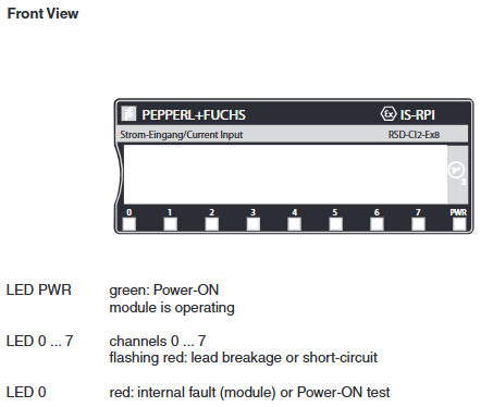
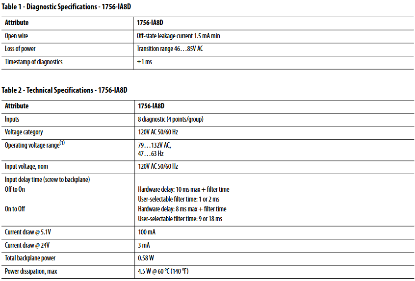
AC digital input 1756-IA8D, 1756-IA16I 120V/240V AC power supply, 1756-IA8D includes point level diagnosis, 1756-IA16I supports channel independent isolation

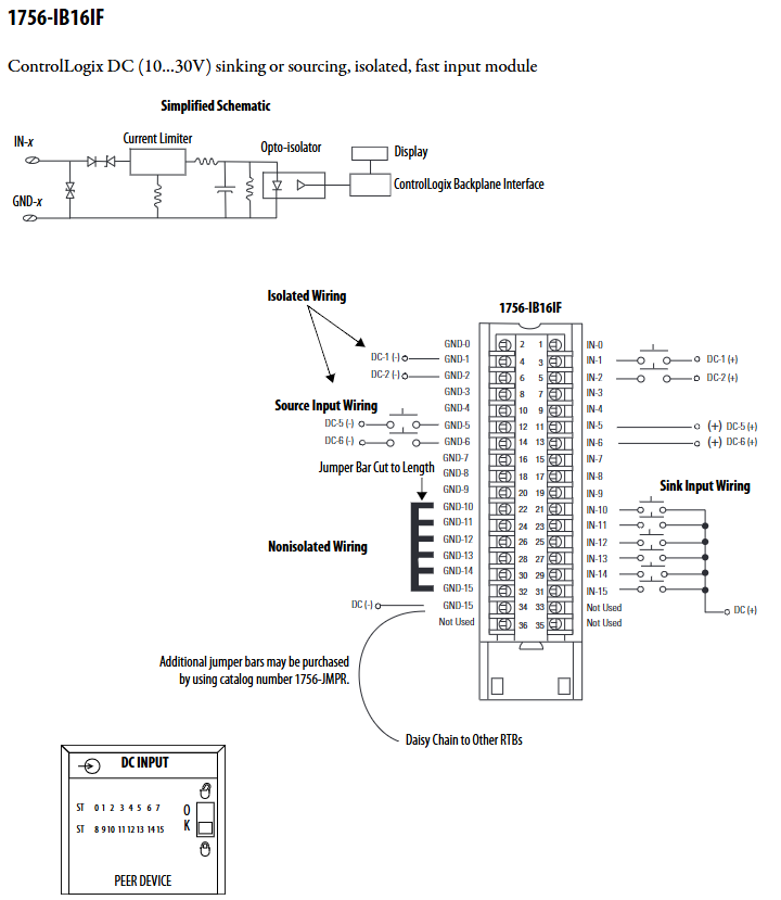
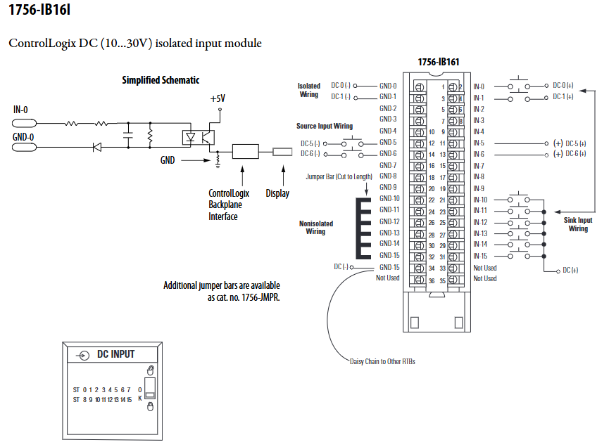
DC digital input 1756-IB16D, 1756-IB16I 12/24V DC sinking/tracing input, 1756-IB16D supports wire breakage detection, 1756-IB16I is fully isolated

AC digital output 1756-OA8E, 1756-OA16I 120/240V AC output, 1756-OA8E with electronic fuse, 1756-OA16I channel independent isolation

DC digital output 1756-OB8EI, 1756-OB16D 12/24V DC output, 1756-OB8EI includes electronic fuse+isolation, 1756-OB16D supports fault diagnosis

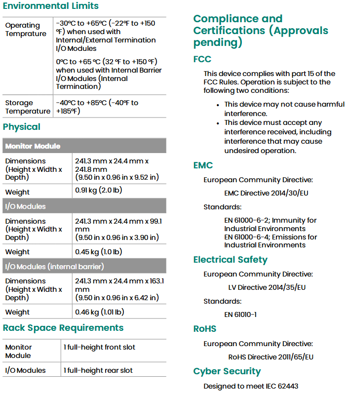
Common parameters: Most digital quantity modules have a working temperature range of 0-60 ℃, a storage temperature of -40… 85 ℃, anti vibration (2g @ 10… 500Hz), anti impact (30g working/50g storage), and EMC compliance with CISPR 11 Class A standards.

(2) Analog quantity I/O module

Used for high-precision acquisition and output of voltage and current signals, supporting multiple ranges and isolation designs, suitable for signal processing of sensors such as pressure and flow sensors.

Module type, typical model, core characteristics

Analog input 1756-IF8, 1756-IF16 support ± 10V/0… 10V/0… 20mA range, 1756-IF16 includes 16 channels, Sigma Delta conversion technology

Analog output 1756-OF4, 1756-OF8I output range ± 10V/0… 20mA, 1756-OF8I supports channel isolation, accuracy 0.1% range

High speed analog I/O 1756-IF4FXOF2F with 4 high-speed inputs and 2 high-speed outputs, sampling time of 300 μ s, supporting floating-point/integer data formats

Accuracy characteristics: The calibration accuracy of most analog modules is better than 0.1% of the range (25 ℃), with a temperature drift coefficient of 15-50 ppm/℃, input impedance voltage type>1M Ω, and current type around 249 Ω.

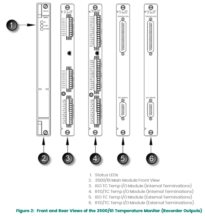
(3) Temperature measurement module

Specially designed for RTD (resistance temperature detector) and thermocouple, supporting multiple types of sensors and temperature ranges, suitable for industrial process temperature monitoring.

Module type, typical model, core characteristics

The RTD input modules 1756-IR6I and 1756-IR12 support RTDs such as Pt100/Pt1000/Ni120/Cu10. The 1756-IR12 includes 12 channels with a range of -200… 870 ℃

Thermocouple input modules 1756-IT6I and 1756-IT16 support thermocouples such as B/E/J/K/R/S/T. 1756-IT16 includes 16 channels and integrates cold junction compensation (CJC)

Mixed temperature module 1756-IRT8I 8-channel configurable RTD/thermocouple, supports ITS-90 linearization, isolation voltage 250V continuous

Temperature range: Thermocouple module covers -270… 2320 ℃ (such as Type C thermocouples), RTD module covers -200… 870 ℃ (Pt100), cold end compensation accuracy ± 0.3 ℃.

(4) HART interface and special modules

Support HART protocol communication and special industrial scenarios, such as safety interlocking, high-speed counting, etc.

Module type, typical model, core characteristics

The HART input modules 1756-IF8H and 1756-IF16H support the HART protocol, 8/16 channel current input, are compatible with HART smart sensors, and have an isolation design

High speed counting module 1756-HSC high-speed pulse counting and position detection, supports multiple counting modes, suitable for motor speed and encoder signal acquisition

Safety module 1756-LSC8XIB8I safety logic control, with 8 inputs and 8 outputs, meets safety standards and is suitable for interlocking in hazardous scenarios

Common core technologies and installation requirements

(1) Electrical and mechanical commonalities

Power supply and power consumption: All modules need to be powered from the rack backplane, with a 5.1V DC current consumption of 100… 400mA (depending on the module type), a 24V DC current consumption of 2… 150mA, and a total backplane power of 0.5… 10W;

Isolation and protection: The isolation voltage is mostly 250V continuous (basic insulation), and some modules (such as 1756-OB8I) support enhanced isolation. The terminal block supports user-defined mechanical key control to prevent misconnection;

Response time: The input delay of the digital module is 0.2… 10ms (configurable filtering), the sampling time of the analog module is 1ms… 50ms, and the minimum sampling time of the high-speed module (such as 1756-IF4FXOF2F) is 300 μ s.

(2) Environmental and installation requirements

Environmental parameter requirement standards

Working temperature: 0… 60 ℃ (some modules can be extended to -20… 70 ℃, please refer to the specific model)

Relative humidity 5… 95% non condensing (IEC 60068-2-30)

Electromagnetic compatibility (EMC) anti ESD: 6kV contact/8kV air discharge; Anti radiation interference: 10V/m (80… 2000MHz)

Installation method: Rack mounted, single slot width (some special modules occupy 2 slots), supports DIN rail or wall mounted rack

Compliance certification and application scenarios

(1) Global Compliance Certification

All 1756 series modules have passed multi regional safety and electromagnetic compatibility certification, with core certifications including:

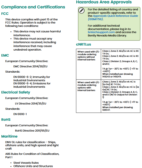
North America: UL Listed (UL Document E65584), CSA Certified (Class I Division 2 Hazardous Area);

Europe: CE certification (compliant with EN 61326-1, EN 61000-6-2/4), ATEX certification (II 3 G Ex nA IIC T4 Gc);

Other: FM hazardous area certification, KC Korean radio certification, C-Tick Australian electromagnetic certification.

(2) Typical application industries

Module based high reliability and flexibility, widely used in:

Process industry: petroleum and natural gas, chemical industry, cement (analog quantity+HART module monitoring pressure/flow);

Discrete manufacturing: automobiles, food and beverage (digital quantity module controls motors/valves);

Energy and Transportation: Power Plants, Ships (Temperature Module Monitoring Equipment Temperature, Safety Module Interlocking).

Key selection and usage tips

Model identification: quick judgment function through model suffix, such as “D”=diagnosis, “E”=electronic fuse, “I”=isolation “H”=HART;

Terminal block selection: Select RTB based on the number of module channels and wiring requirements. For example, 1756-TBCH is suitable for multi-channel isolation modules, while 1756-TBNH is suitable for ordinary digital modules;

Calibration cycle: It is recommended to calibrate the analog and temperature modules every 6-12 months to ensure accuracy;

Dangerous area use: For Class I Division 2 areas, modules with corresponding certifications (such as CSA LR69960C, FM certification) should be selected to avoid direct use of non certified modules.

​Molex SST-ESR2-CLX-RLL and SST-SR4-CLX-RLL

System and hardware requirements

(1) System requirements

Category specific requirements

PC hardware should have at least an Intel Pentium 4 processor, 512MB of memory, and 100MB of available hard disk space; Suggest a 17 inch/19 inch (1280 × 1024 and above resolution) monitor; CD/DVD drive, power cable, Ethernet cable, keyboard and mouse required

The PAC/PLC power ESR2 module consumes 5VDC 850mA and 24VDC 1.75mA; The SR4 module consumes 5VDC 1004mA and 24VDC 1.75mA. Please refer to the CLX 5000 modular installation and operation manual to calculate the total power load

The PC operating system supports Windows XP, Vista, 7, and 8

Other requirements: 1. Support for Rockwell Automation RSLogix 5000 Additional Instructions (AOI) requires RSLogix 5000 V16 or above, module firmware must be 2.10.2 or above (general configuration file) or 2.12.1 or above (additional configuration file/AOP), BCMS software must be 1.9 or above

2. Support for RSLogix 5000 additional configuration files (AOP) requires RSLogix 5000 V15 or above version, module firmware 2.3.0 or above, BCMS software 1.7.0 or above, and AOP only supports maximum input/output/status INT size (250, 248, 250), small size requires 1756 universal configuration file

(2) Hardware and Packaging

package contents

The module model includes items and quantities

SST-ESR2-CLX-RLL 1 communication module, 2 RJ45 to DB9 serial cable adapters, 1 Windows system installation CD (including BCMS software), PDF versions of the CD including user guide, Siemens Industrial Ethernet protocol guide, Modbus TCP/serial protocol guide

SST-SR4-CLX-RLL 1 communication module, 4 RJ45 to DB9 serial cable adapters, 1 Windows system installation CD (including BCMS software), CD containing user guide, Modbus serial protocol guide PDF version (Siemens Industrial Ethernet, Modbus TCP protocol guide PDF included but not applicable)

Hardware features: All include status LEDs (COMM, SYS, OK, indicating communication/connection/initialization status respectively), RJ45 serial interface (connecting RS232/422/485 devices with transmit/receive indicator lights), USB configuration port (downloading configuration/upgrading firmware); ESR2 additionally includes an RJ45 Ethernet interface (connected to industrial networks with activity/link indicator lights), while SR4 does not have an Ethernet interface; All have self-locking tongue fixing modules, and LCD displays firmware version, connection status, IP address, and other information.

Core functions and software

(1) Core functions of the product

Differences and Commonalities of Modules

Function SST-ESR2-CLX-RLL SST-SR4-CLX-RLL

Number of interfaces: 1 Ethernet port+2 serial ports+4 serial ports

Supports protocol Modbus TCP/serial, Siemens S5/S7 communication only Modbus serial communication

Common feature 1. Supports two database addressing modes: default and extended. In default mode, 0-699 address mapping is used for CLX input/output/status tables. In extended mode, 30K address mapping can be customized

2. Support cyclic function (read and write data periodically, up to 255 per channel), which can be dynamically triggered

3. Supports AOI/AOP and CIP messaging (reading and writing databases, triggering cyclic functions)

4. Supports remote rack configuration, Listen Only mode, and can be configured as client/server (master-slave) mode

Protocol support details: Modbus supports function codes such as FC3 (read multiple registers), FC6 (write single registers), FC16 (write multiple registers), etc; Siemens S5/S7 supports reading and writing of variable types such as ABx/AWx, EBx/EWx, MBx/MWx, DBx.DBx, etc.

(2) Software and Tools

BCMS software: Brad Communication ™  The SST backplane communication module software includes Configuration Manager (managing configuration files, such as creating/uploading/downloading configurations, modifying IP addresses), Console (configuring ports/protocols/devices, creating cyclic functions, including tools such as PCInit/ReadWait/WriteWait). After installation, the configuration files, AOI files, and firmware are stored in the corresponding system paths (Windows XP/7 paths differ).

Diagnostic and management tools: including Visucyc (monitoring cyclic function status), Network Diagnostic (diagnosing ESR2 Ethernet activity), Firmware Installer (upgrading firmware), etc., supporting module connection through USB, RSLinx, TCP/IP, and other methods.

Configuration and Operation Guide

(1) Quick configuration process

Backplane communication verification: The module supports live plugging and unplugging (RIPP). During installation, align the guide rail and insert it into the rack. Configure the EtherNet/IP driver through RSLinx and browse the rack to confirm that the module is recognized (ESR2 product code 53, SR4 product code 54).

Module configuration (RSLogix 5000)

AOP configuration (recommended): You need to install the AOP installation package first, add the SST-ESR2/SR4-CLX-RLL module to RSLogix 5000, configure the slot, connection type (Output w/Status/Sten Only), RPI (5-750ms), program mode output status (such as Zero CyclicRuns), and ensure that the configuration name is consistent with the module.

General configuration file: Add 1756-MODULE, set communication format (such as Data INT with Status), assembly instance and size for input/output/configuration/status (such as input instance 1, size 250).

Initialization and Address Mode Switching: Initialize the module through Console’s PCInit; The database address mode can be switched in Configuration Manager. The default mode maps the CLX table from 0-699, and the extended mode allows customization of input/output/status addresses and lengths (firmware 2.10.2 or above is required).

(2) Typical Configuration Example

Modbus TCP configuration: ESR2 can be configured as a server (select Modbus TCP protocol), client (add Modbus device, set IP address), or both client and server, creating cyclic functions (set cycle, data volume, device address, database offset).

Modbus serial configuration: Both modules can be configured as slaves (select Modbus RTU/ASCII Slave) or hosts (add Modbus slave devices, set slave numbers), supporting multi-channel master-slave hybrid configuration.

Siemens S7/S5 configuration: Only supported by ESR2, can be configured as a server/client, adding devices such as S7 300/400/1200, creating cyclic functions to read and write variables such as DBx.DWx.

Compliance and Support

(1) Compliance certification

Compliant with CE/EU, RoHS, FM (Class 1 Div 2 Groups A-D), FCC, Korean certification, RINA certification, electrical safety complies with EN 61010-1, EMC complies with EN 61000-6-2/4.

(2) Warranty and Support

Warranty: According to Molex standard warranty terms, please refer to Appendix F of the document for details.

Technical Support: You can contact Molex Canada at 216 Bathurst Drive, Waterloo, Ontario, Canada N2V 2L7; Phone: 1.775.782.3611 or 1.800.227.5514 (US only), or visit the official website Bently.com for patent information and the latest documents.

ABB ACS880-01-025A-3 frequency converter

Basic product information

(1) Core identification and specifications

Core parameters: rated power 11.0kW, input current 25A, product model ACS880-01-025A-3, product ID 3AUA0000107992, EAN code 6438177557197.

Production and ordering: The country of origin is Finland (FI) and Saudi Arabia (SA), with customs tariff code 85044084, and it belongs to customized production (Made To Order); The minimum order quantity is 1 piece, the order multiple is 1 piece, and the sales measurement unit is “piece”, not just the quoted product.

Packaging and dimensions: The net weight of the product is 8.4kg, and the net dimensions (depth/length x height x width) are 249mm x 409mm x 155mm; the first level packaging dimensions (depth/length x height x width) are 574mm x 304mm x 256mm, with one piece per box and a total volume of 15.785dm ³.

Application and installation features

(1) Applicable scenarios

Industry adaptation: customized for industries such as oil and gas, mining, metallurgy, chemical, cement, power plants, material handling, pulp and paper, sawmills, ships, water supply and drainage, food and beverage, automobiles, etc.

Load type: can control various equipment such as cranes, extruders, winches, coilers, conveyors, mixers, compressors, centrifuges, test benches, elevators, pumps, fans, etc.

(2) Installation and Protection

Installation method: The standard is wall mounted installation, and installation inside the cabinet is optional.

Protection level: The shell protection level is IP21, and the NEMA protection type is Type 1, suitable for most industrial environments; The maximum working environment temperature is 40 ℃, the sound pressure level is 59dB (A), and the operating noise is relatively low.

Key technical parameters

(1) Electrical input and output

Category parameter details

Input parameters: 3-phase power supply, frequency 50/60Hz, input voltage 380-415V

The output current (under different operating conditions) is typically 25A, 24A for light overload, and 17A for heavy load

The output power for both regular and light overload use is 11kW, with an apparent output power of 17kV · A

Efficiency related efficiency level IE2, standby loss 23W; efficiency varies under different operating conditions (such as 95.6% efficiency at 50Hz/100% current)

(2) Communication and Interface

Communication Protocol: Supports MODBUS、DeviceNet、PROFIBUS、PROFIsafe、CAN、EtherNet/IP、PROFINET IO、TCP/IP  And other bus systems.

Hardware interface: including 1 RS-485 interface, 1 USB interface, and 6 other interfaces; No industrial Ethernet PROFINET、RS-232、RS-422、 Parallel interface.

Signal ports: 2 analog inputs, 2 analog outputs, 6 digital inputs/5 digital outputs; With control unit, no optical interface, supports PC connection.

(3) Efficiency details (compliant with IEC 61800-9-2 standard)

Operating conditions (frequency/current) absolute loss relative loss efficiency

0Hz / 25% 126W 0.7% 87.9%

0Hz / 50% 168W 1.0% 91.3%

0Hz / 100% 301W 1.7% 92.2%

50Hz / 25% 135W 0.8% 93.4%

50Hz / 50% 185W 1.1% 95.2%

50Hz / 100% 342W 2.0% 95.6%

90Hz / 50% 203W 1.2% 97.0%

90Hz / 100% 412W 2.4% 97.0%

Classification and Environmental Information

(1) Product classification

Series affiliation: ACS880 series, product type is low-voltage AC frequency converter, specifically classified as “frequency converter → low-voltage AC frequency converter → industrial frequency converter → ACS880 single machine frequency converter → ACS880-01 wall mounted single machine frequency converter”.

Standard classification: ETIM 7 is classified as EC001857 (≤ 1kV frequency converter), UNSPSC is classified as 39122001.

(2) Environmental compliance

WEEE category: 5 categories (small equipment, with external dimensions not exceeding 50cm).

SCIP code: Finland (FI) code 090be974-b30f-4eaa-b924-275d6a7f6686; Belgium (BE), the Netherlands (NL), Denmark (DK), Spain (ES), Portugal (PT), Estonia (EE) and other countries each have their own simplified SCIP codes.

SKiiP 1213 GB123-2DL V3 module

Module foundation and core characteristics

SKiiP 1213 GB123-2DL V3 is a SKiiP under SEMIKRON ® The 3-series 2-in-1 integrated intelligent power system has high integration and industrial grade reliability, with the following core features:

Core technology: Built in SKiiP technology, using trench insulated gate bipolar transistors (Trench IGBTs) and CAL HD diode technology, balancing efficient switching and low loss;

Integrated components: Equipped with current sensors, temperature sensors, and heat sinks, reducing the need for external accessories and simplifying installation;

Compliance certification: UL certified, document number E63532, meets industrial safety standards.

Typical application scenarios cover fields with high requirements for power control, such as renewable energy, traction systems, elevators, and industrial transmissions (note: MKP capacitors that are compatible with each terminal need to be used).

Key electrical parameters (unless otherwise specified, ambient temperature Ts=25 ℃)

(1) Absolute maximum rated value

Category parameter symbol condition description numerical unit

System VCC working DC link voltage 900 V

Visol DC for 1 second, main terminal to heat sink 4300 V

It (RMS) per AC terminal, terminal temperature<115 ℃ 400 A

IFSM junction temperature Tj=150 ℃, pulse width tp=10ms, sine 180 ° 6900 A

I ² t Tj=150 ℃, tp=10ms (diode) 238 kA ² s

Tstg storage temperature -40~85 ℃

IGBT VCES Tj=25℃ 1200 V

IC Tj=150℃,Ts=25℃ 1145 A

IC Tj=150℃,Ts=70℃ 882 A

ICnom rated current 1200 A

TJ junction temperature (note: -40~150 ℃) -40~150 ℃

Diode VRRM Tj=25 ℃ 1200 V

IF Tj=150℃,Ts=25℃ 925 A

IF Tj=150℃,Ts=70℃ 700 A

IFnom rated forward current 930 A

Tj junction temperature -40~150 ℃

Driver Vs power supply voltage 13~30V

ViH input signal high level voltage 15+0.3 V

VisolPD QPD≤10pC, 1170 V from the primary side to the power end

Dv/dt secondary to primary voltage change rate of 75 kV/μ s

FSW switch frequency 15 kHz

(2) Key characteristic parameters

Category parameter symbol condition description Minimum value Typical value Maximum value Unit

IGBT VCE (sat) IC=600A, Tj=25 ℃ (at the terminal) 1.7-2.1 V

VCE (sat) IC=600A, Tj=125 ℃ (at the terminal) -1.9-V

Eon+Eoff IC=600A,VCC=600V,Tj=125℃ – 221 – mJ

Eon+Eoff IC=600A,VCC=900V,Tj=125℃ – 390 – mJ

Rth (j-s) each IGBT switch, junction to heat sink thermal resistance -0.03 K/W

Diode VF (VEC) IF=600A, Tj=25 ℃ (at the terminal) 1.50-1.80 V

Err IF=600A,VR=600V,Tj=125℃ – 42 – mJ

Err IF=600A,VR=900V,Tj=125℃ – 56 – mJ

Rth (j-s) each diode switch, junction to heat sink thermal resistance -0.058 K/W

Driver Is current formula: 240+k1fsw+k2IAC (k1=29mA/kHz, k2=0.00065mA/A ²) — mA

ITRIPSC overcurrent trip level 1470 1500 1530 A (peak)

Tttrip over temperature trip level 110 115 120 ℃

System Rth (r-a) flow rate=460m ³/h, Ta=25 ℃, altitude 500m -0.0344 K/W

LCE commutation inductor -6- nH

W Weight without heat sink -1.7kg

WH heat sink weight -4.4kg

Isolation and environmental requirements

(1) Isolation coordination (compliant with EN 50178 and IEC 61800-5-1)

Grid voltage: The maximum RMS value of the grounding triangle grid line voltage is 480V+20%, corresponding to an installation altitude of 2000m; the maximum RMS value of the star point grounding grid line voltage is 480V+20%, corresponding to an installation altitude of 5000m;

Transient voltage: The maximum transient peak voltage between the low-voltage circuit and the power grid is 1600V;

Protection level: The heat sink is basically isolated from the power grid, with a protection level of IP00 (compliant with IEC 60529);

Pollution level: molded power part external pollution level 2 (compliant with IEC 60664-1);

Overvoltage category: Grid side overvoltage category III (compliant with IEC 60664-1).

(2) Environmental conditions (compliant with IEC 60721)

Environmental scenario, climate conditions, biological conditions, chemical active substances (excluding salt spray), mechanical active substances, mechanical conditions, pollution of fluids

Storage: 1K2 1B1 1C2 1S1 1M3 (customer customized packaging without declaration)-

Transport 2K2 (extended temperature range -40~85 ℃, shortened operating life near 85 ℃) 2B1 2C1 2S1–

Weather protection fixed use 3K3/1 3B1 3C2 3S1 3M6 (3M7 is feasible but limited by external components)-

Ground installation operation 5K1m 5B1 5C2 5S1 5M3 (no foreign objects/stone impact) 5F1

Ship Environment Operation -6B1 6C2 6S1 6M3-

Other key information

Thermal characteristic chart: including IGBT/diode output characteristics, energy loss (E=f (Ic, VCC)), flow rate and voltage drop/thermal resistance relationship, transient thermal impedance and other charts (as shown in Figure 1-9), which can be used for thermal design and loss calculation;

Mechanical dimensions: Provide detailed installation dimensions for modules and heat sinks (such as bolt specifications M4/M5/M6/M8, installation depth, spacing, etc.), which need to be mechanically assembled according to the drawing parameters;

Electrostatic sensitivity: It belongs to electrostatic discharge sensitive devices (ESDS) and should be operated in accordance with the specifications in Chapter 9 of IEC 60747-1;

Usage tip: Component specifications do not represent feature guarantees, and specific application testing is required; Prior written approval from SEMIKRON is required for use in life support equipment, and it is recommended to consult the manufacturer before use.

image.png

Bently 3500/60 and 3500/61 temperature modules

Module Core Overview

Bently Nevada’s 3500/60 and 3500/61 temperature modules both have 6-channel temperature monitoring capabilities and are compatible with resistance temperature detectors (RTDs) and thermocouples (TCs) inputs. They can condition input signals and compare them with user programmable alarm thresholds. The core functions of the two are the same, the only difference being that the 3500/61 provides recorder outputs for each of the six channels, while the 3500/60 does not have this function.

The module needs to be set to RTD or TC measurement mode through the 3500 rack configuration software, providing multiple I/O module versions:

RTD/TC non isolated version: can be flexibly configured to receive only TC, only RTD, or a combination of both inputs;

TC Isolation Edition: Equipped with 250Vdc inter channel isolation capability, it can resist external interference.

In the Triple Modular Redundancy (TMR) configuration, three temperature monitors need to be installed adjacent to each other, and the system ensures operational accuracy through two voting mechanisms to avoid single point failures.

Key technical parameters

Measurement range: TC (Type J/K/T/E, Range reduction at high temperature for Type E); RTD (made of platinum/nickel/copper material, with some parts having a narrower range after external barriers, platinum RTD (α=0.00385) is an industry standard).

Output and accuracy: The front panel has OK/TX/RX/Bypass LEDs; RTD current source 925 ± 15 μ A (25 ℃); Temperature resolution of 1 ℃/℉, accuracy of ± 1-3 ℃ (depending on configuration), alarm accuracy of ± 0.13%, supporting warning (1-60 second step size of 1 second), danger (1-60 second step size of 0.5 seconds) delay.

Environment and size: working temperature 0-65 ℃ (with internal barriers), storage temperature -40-85 ℃; Monitor module 241.3 × 24.4 × 241.8mm (0.91kg), with slightly smaller I/O module size/weight, each occupying one full height slot.

image.png

Compliance and Ordering

Certification: Compliant with FCC, EMC (2014/30/EU), RoHS, IEC 62443 network security, up to SIL 2, certified for hazardous areas such as CSA/ATEX (with or without internal barriers).

Order: Both 3500/60 (without recorder) and 3500/61 (with recorder) are “Model – AA (I/O type) – BB (certified)”, with accessories including terminal blocks, cables of different lengths (assembled/unassembled), and specialized spare parts.

Ordering and accessory information

(1) Module Ordering Model

3500/60 (without recorder output): Model format 3500/60-AA-BB

AA (I/O module type): 01 (RTD/TC non isolated internal terminal), 02 (RTD/TC non isolated external terminal), 03 (TC isolated internal terminal), 04 (TC isolated external terminal), 05 (RTD/TC non isolated with internal barrier)

BB (Institutional Certification Options): 00 (No Certification), 01 (CSA/NRTL/C, Class I, Zone 2), 02 (ATEX/IECEx/CSA, Class I, Zone 2)

3500/61 (with recorder output): Model format 3500/61-AA-BB, AA and BB options have the same meaning as 3500/60

(2) External terminal block

Model Description

133908-01 RTD/TC non isolated external terminal block (terminal block connector)

133916-01 RTD/TC non isolated external terminal block (European connector)

133924-01 TC Isolation External Terminal Block (Terminal Block Connector)

133932-01 TC isolated external terminal block (European connector)

133892-01 3300/61 Recorder Output External Terminal Block (Terminal Block Connector)

133900-01 3300/61 Recorder output external terminal block (European connector)

(3) Cable

3500/60 and 3500/61 sensors (XDCR) signal to external terminal (ET) block cable: model 134544-AAAA-BB

AAAA (length): 0005 (5 feet/1.5 meters), 0007 (7 feet/2.1 meters), 0010 (10 feet/3.0 meters), 0025 (25 feet/7.5 meters), 0050 (50 feet/15 meters), 0100 (100 feet/30.5 meters)

BB (assembly instructions): 01 (unassembled), 02 (assembled)

3500/61 recorder output to external terminal (ET) block cable: model 134543-AAAA-BB, AAAA (length) option is the same as the above cable, BB (assembly instructions) 01 (not assembled), 02 (assembled), and the recorder cable is not used for/60 or/62 monitors

(4) Spare parts

3500/60 and 3500/61 share spare parts: including various external terminal blocks, connector plugs (such as 00580442: 9-position green internal terminal connector plug), 3500/60&61 user guides (134542), etc

3500/60 specialized spare parts: such as 163179-01 (3500/60 temperature monitor, no recorder), 133827-01 (3500/60 RTD/TC non isolated external terminal I/O module), etc

3500/61 specialized spare parts: such as 163179-02 (3500/61 temperature monitor with recorder), 133819-02 (3500/61 RTD/TC non isolated internal terminal I/O module), etc

ABB ACS880-01-025A-3 frequency converter

Product classification and structural design

The ACS880 series is divided into three categories based on installation method and power range, suitable for different industrial environment requirements:

Structure type, power range, typical application scenarios, core characteristics

Wall mounted (Type 01) 0.55kW-75kW small and medium power single machine control (such as fans, water pumps, conveyor belts) with compact size, IP21 protection (preventing vertical dripping and solid foreign objects), natural cooling or forced air cooling, suitable for installation in control cabinets/dry environments

Cabinet style (04/06 type) 11kW-2800kW high-power or complex control (such as rolling mill, compressor, centrifuge) independent cabinet design, IP21/IP54 protection optional, built-in cooling system (air-cooled/water-cooled), integrated input circuit breaker, reactor and other accessories, supports multi machine linkage

Modular (02 type) 160kW-2800kW ultra high power scenarios (such as mine hoists, large fans) modular components (power modules, control units, auxiliary modules) that need to be matched with user made cabinets, support redundant design, and adapt to customized systems

Electrical performance and speed regulation capability

The manual specifies the series of general electrical parameters, and the differences between different models are distinguished by the “model suffix” (such as voltage level, power code):

Input voltage range:

Low voltage series: 200-240V AC (single-phase/three-phase), 380-480V AC (three-phase), 500-690V AC (three-phase), all supporting ± 10% voltage fluctuation;

Frequency adaptation: 50/60Hz (± 5% fluctuation), compatible with global grid frequencies.

Output performance:

Output frequency: 0-500Hz (standard), 0-1000Hz (high frequency optional), supporting high-speed motor speed regulation;

Speed control accuracy: open-loop V/F control ± 0.5% rated speed, closed-loop vector control ± 0.1% rated speed;

Starting torque: 150% rated torque @ 0Hz under vector control (suitable for heavy-duty starting, such as crushers and extruders).

Control mode:

Basic mode: V/F control (square torque/constant torque curve optional, suitable for loads such as fans and pumps);

Advanced modes: sensorless vector control (no encoder required, suitable for scenarios without position feedback), closed-loop vector control (with encoder, high-precision speed regulation), torque control (constant torque output, such as curling equipment);

Special functions: synchronous control (multi motor speed/torque synchronization), process PID control (built-in PID regulator, directly related to process parameters such as pressure and flow), energy-saving mode (automatic optimization of voltage frequency ratio, reducing no-load losses).

Safety and protection functions

The manual emphasizes the safety design of the series, which complies with international safety standards such as IEC 61800-5-1. The core protection functions include:

Motor protection: overcurrent, overload (inverse time characteristic), locked rotor, phase loss, over temperature (supporting motor PTC thermistor connection), insulation monitoring;

Inverter protection: DC bus overvoltage/undervoltage, IGBT module overheating, input phase loss, output short circuit, ground fault (optional residual current detection), lightning surge protection;

System safety: Safe torque shutdown (STO, SIL2 certification, cutting off motor torque output in emergency situations), safe stop (SS1/SS2, compliant with EN ISO 13850), adapted to industrial safety circuit design.

Communication and integration capabilities

The ACS880 series supports multi protocol communication, making it easy to connect to PLC, DCS, or upper computer systems. The manual provides detailed instructions on the configuration methods for each protocol

Standard communication: RS485 interface (supporting Modbus RTU protocol), used for local small-scale communication;

Optional modules: Profinet, EtherNet/IP, DeviceNet, CANopen, Profibus DP and other industrial Ethernet modules to achieve high-speed remote monitoring and multi device linkage;

ABB exclusive protocol: Supports ABB DriveBus and can quickly network with ABB PLC (such as AC500) or other ACS880 frequency converters, simplifying synchronous control configuration.

Manual Key Operation Guide (Installation, Debugging, and Maintenance)

1. Installation and wiring specifications

The manual specifies the prerequisites for safe installation (such as power-off operation, electrostatic protection) and core steps:

Installation environment requirements: working temperature -25~40 ℃ (some models can be extended to -40~50 ℃), relative humidity 5% -95% (no condensation), altitude ≤ 1000m (reduced capacity is required for use at high altitudes), away from dust, corrosive gases, and strong electromagnetic interference sources;

Wiring points:

The main circuit (input L1/L2/L3, output U/V/W) needs to match the cross-sectional area of the wires (according to the rated current), and install input circuit breakers and reactors (to suppress harmonics, optional);

Shielded wires are required for control circuits (analog I/O, digital I/O, encoder interfaces), with the shielding layer grounded at one end to avoid parallel laying with the main circuit cable (reducing interference);

The safety circuit (STO, emergency stop) needs to be independently wired to ensure that protection is triggered first in case of a fault.

2. Debugging process and parameter configuration

The manual provides standardized debugging steps, suitable for most application scenarios:

Pre power on inspection: Confirm correct wiring (no short circuit, virtual connection), grounding resistance ≤ 4 Ω, parameter reset (default factory settings);

First power on: first turn on the control power supply (check if the panel display is normal), then turn on the main power supply (continue only if there are no fault alarms);

Motor identification: Implement the “motor identification” function (static/dynamic identification optional), the frequency converter automatically reads motor parameters (such as rated power, current, impedance), and optimizes control accuracy;

Core parameter settings: Configure key parameters based on load characteristics (such as control mode P100, rated speed P304, starting torque P640, acceleration/deceleration time P221/P222);

Trial operation: First, jog the motor to test the direction of rotation (to avoid equipment damage caused by reverse rotation), then gradually increase the speed to the rated value, and monitor whether the current and temperature are normal.

3. Fault diagnosis and maintenance

The manual includes a “fault code table” that details the causes and troubleshooting methods of common faults (such as F001 overcurrent, F002 overvoltage, F003 overheating), and provides maintenance recommendations:

Daily maintenance: Clean the heat dissipation channel (dust screen, heat sink) weekly, check the tightness of the wiring terminals monthly, and check the insulation resistance quarterly (main circuit to ground ≥ 1M Ω);

Regularly replace components: cooling fan (with a lifespan of about 2-3 years), electrolytic capacitor (with a lifespan of about 5-8 years, adjusted according to the ambient temperature). The manual specifies the vulnerable part models and replacement steps for different models;

Fault record: The frequency converter can store the last 20 fault information (including fault time, current/voltage/speed at the time of the fault), which can be read through the panel or communication interface to assist in locating the root cause.

Emerson DeltaV S-series Traditional I/O Modules

The Emerson DeltaV S-series traditional I/O module is a modular input/output subsystem designed specifically for DeltaV distributed control systems (DCS). Its core positioning is to enhance the flexibility, reliability, and installation and operation efficiency of industrial process control. It is suitable for industrial scenarios such as petrochemicals, electricity, and energy that require high environmental adaptability and system stability. It can achieve precise acquisition and output of analog and discrete signals.

Core Features and Advantages

Modular and flexible architecture

Scalable design: A single controller can support up to 8 I/O carriers, with a total of 64 I/O slots. It supports mixing various I/O modules such as analog (AI/AO) and discrete (DI/DO) to meet the signal acquisition and control needs of different scenarios.

On demand configuration: Supports the “on-demand procurement” mode, allowing for the selection of I/O cards, 8-slot carriers, power supplies/controllers, and other components based on the system size. These components can be flexibly added as the system expands, avoiding resource waste.

Efficient installation and maintenance

Tool free installation: The carrier is fixed to the T-shaped DIN rail through a buckle, and the I/O module is directly inserted into the slot without the need for tools; All wiring is completed through carriers and terminal blocks, and there is no need to disconnect on-site wiring when replacing modules, reducing maintenance downtime.

Error proof design: Each I/O module and terminal block is equipped with a dedicated “key positioning” mechanism (two rotatable positioning columns, 6 position combinations), allowing only matching modules to be inserted into the corresponding terminal block to avoid the risk of incorrect installation.

Integrated power supply: The I/O carrier is equipped with a 24V DC bus based on-site power distribution, which is divided into primary/secondary power supplies for odd/even slots. Each slot is independently protected by a fuse, reducing the design of external power supply circuits and ensuring that single card failures do not affect other modules.

Online Expansion and High Availability

Online expansion: Supports adding I/O carriers with power on (directly connected to the right side of existing carriers or installed on other DIN rails through extension cables). The controller automatically detects new carriers and modules and enters them into the configuration database without interrupting existing I/O communication.

1: 1. Redundant backup: 4 types of critical I/O cards (such as 8-channel AI/AO, 32 channel DI/DO) support redundant configuration, and can be automatically recognized as redundant pairs by the system when installed in pairs on redundant terminal blocks. In the event of a fault, the switching can be completed within 2 I/O bus scanning cycles (signal overlap<5ms during analog switching, and digital “first on, then off” to ensure uninterrupted power supply to the device), without the need for additional configuration.

Adaptability to harsh environments

Wide temperature operation: All I/O modules operate within a temperature range of -40~70 ℃ (-40~158 ℉) and can be installed in on-site cabinets to reduce the control room footprint and shorten the length of multi-core cable wiring, thereby lowering costs.

Anti interference and anti-corrosion: Complies with ISA-S71.04-1985 G3 level anti-corrosion standard (using normal coating), anti impact (10g half sine wave, 11ms), anti vibration (1mm peak to peak value at 5-13.2Hz, 0.7g at 13.2-150Hz), suitable for complex electromagnetic and environmental interference in industrial sites.

Core product composition and I/O module classification

1. Subsystem composition

The traditional I/O subsystem of DeltaV S-series mainly includes the following components:

I/O carrier: DIN rail installation, carrying all I/O components, providing bus power supply and communication interfaces, divided into 8 slot horizontal carriers and other types.

Power supply: Large capacity AC to 24V DC power supply, providing power for on-site equipment and I/O modules.

I/O module: including analog input/output, discrete input/output and other types, all of which adopt a unified appearance design and are used with dedicated terminal blocks.

Auxiliary accessories: Cable extender (flexible adjustment of carrier installation position), terminal block (standard/fused/redundant type), Mass connection module (compatible with third-party wiring schemes).

2. I/O module types and key parameters

The modules are divided into two categories: analog (AI/AO) and discrete (DI/DO), and support simplex (single-mode) or redundant (redundant) installation. The following are the core module specifications:

(1) Analog input (AI) module

Module type, channel number, signal type, key parameters

AI 4-20mA HART 8 4-20mA (2/4 wire system) resolution 16 bits, accuracy of 0.1% range at 25 ℃, channel optical isolation 1500V DC, supporting HART transparent transmission (scan time 600-800ms/channel)

AI Plus 4-20mA HART 16 4-20mA (2/4-wire system) resolution 16 bits, accuracy 0.2% range, channel optical isolation 1000V DC, supports Mass terminal block and fault detection

RTD module 8 Pt100/Pt200/Ni120 2/3/4 wire system, excitation current 100 μ A, Pt100 measurement range -200~850 ℃, accuracy ± 0.5 ℃ (25 ℃)

Thermocouple/mV module 8 B/E/J/K/N/R/S/T type thermocouple, mV signal cold end compensation ± 1 ℃, mV range -100~100mV, accuracy ± 0.1mV (25 ℃)

Isolation type AI module 4 thermocouples/mV/V/RTD channel optical isolation 1500V DC, supports wide range voltage signals (0-5V/0-10V, etc.), and improves accuracy (such as E-type thermocouples ± 0.5 ℃)

(2) Analog Output (AO) Module

Module type, channel number, signal type, key parameters

AO 4-20mA HART 8 4-20mA resolution 14 bits, -40~60 ℃ accuracy 0.25% range, channel optical isolation 1500V DC, supports open circuit detection (<0.7mA)

AO Plus 4-20mA HART 16 4-20mA resolution 14 bits, accuracy 0.25% range, channel optical isolation 1000V DC, supports Mass terminal block, maximum on-site power supply 400mA@24V  DC

(3) Discrete Input (DI) module

Module type, channel number, signal type, key parameters

DI 24V DC dry contact 8 dry contact (compatible with NAMUR sensor) with conductivity detection>2.2mA, shutdown<1mA, input impedance 5k Ω, channel optical isolation 1500V DC

DI Plus 24V DC dry contact 32 24V DC dry contact conductivity detection>2mA, shutdown<0.25mA, supports terminal fault detection (requires Mass terminal block), on-site power supply 150mA@24V  DC

Pulse Counting Input (PCI) 4 24V DC frequency range 0.1Hz~50kHz, minimum pulse width 10 μ s, 32-bit unsigned counter, channel optically isolated 1500V DC

Sequence of Events (SOE) input 16 24V DC dry contact channel scan rate 0.25ms/16 channels, timestamp accuracy ± 0.25ms (single card)/± 1ms (single controller), supports event logging

DI 120V AC isolation type 8 120V AC conduction detection 84~130V AC, turn off 0~34V AC, input impedance 60k Ω, channel to channel optical isolation 250V AC

(4) Discrete Output (DO) module

Module type, channel number, signal type, key parameters

DO 24V DC high side 8 24V DC maximum 1A continuous output per channel (surge 4A<100ms), turn off leakage<1.2mA, channel optical isolation 1500V DC

DO Plus 24V DC high side 32 24V DC output of 100mA per channel, cut-off leakage<0.1mA, supports terminal fault detection, on-site power supply 3.2A@24V  DC

DO 120/230V AC isolation type 8 120/230V AC maximum 1A continuous output per channel (surge 5A<100ms), turn off leakage 2mA (120V AC)/4mA (230V AC), channel to channel optical isolation 250V AC

image.png

Terminal block and system compatibility

1. Terminal block type and adaptation

Terminal blocks are divided into standard terminal blocks, fuse terminal blocks, redundant terminal blocks, and Mass terminal blocks. Different I/O modules require dedicated terminal blocks, and the core adaptation relationship is as follows:

Example features of terminal block type adaptation module

8-channel standard terminal block, 8-channel AI/AO, 8-channel DI/DO basic wiring, supporting single-mode installation

8-channel fuse terminal block. All 8-channel modules are equipped with 2A fuses to protect the on-site circuit

Redundant 8-channel terminal block with 8-channel redundant AI/AO and DI/DO supports parallel installation of 2 modules to achieve redundant backup

Mass terminal block (16/24/40/48 pins) Plus series modules, some standard modules are compatible with S-series Mass connection solutions or third-party devices (such as Pepperl+Fuchs HiC safety barriers), optimizing on-site wiring

2. System compatibility requirements

Controller: SQ or SX series controllers are required, and V11.3.1 and above versions of the DeltaV system support S-series and M-series controllers running on the same network.

Software version: The Plus series modules (16 channel AI/AO, 32 channel DI/DO) require DeltaV v13.3 or higher.

Installation restrictions: only supports horizontal carriers, not compatible with vertical carriers; Vertical I/O applications require the use of CHARMS electronic grouping I/O.

Certification and Security Standards

International certification:

Electrical safety: CE (EN 61326-1), FM (3600/3611), CSA (C22.2 No.213/1010-1).

Explosion proof certification: ATEX(II 3G Ex ec IIC T4 Gc)、IECEx(II 3G Ex ec IIC T4 Gc)、FM/CSA Class I, Division 2(Groups A-D, T4)。

Classification certification: IACS E10, ABS design evaluation certificate, DNV marine certificate.

Safety design:

Isolation protection: All module channels are optically isolated from the system (1000~1500V DC), and some discrete module channels are additionally isolated from each other.

Fault alarm: Hardware faults (such as module failure, communication interruption, on-site wiring failure) automatically trigger system alarms, with logs recorded in the Event Chronicle, and support for real-time viewing of module status on the diagnostic interface.

Order

1. Core module ordering model (example)

Module Description Model Example

8-channel AI 4-20mA HART (with AI 8-channel terminal block) SE4003S2B1

16 channel AO Plus 4-20mA HART (with 48 pin Mass terminal block) SE4005S2B5

32 channel DI Plus 24V DC (with redundant 40 pin Mass terminal block) SE4081S2T2B7

8-channel DO 120/230V AC isolated type (with fuse terminal block) SE4002S2T1B2

image.png

HONEYWELL EXCEL 5000 OPEN SYSTEM

The Honeywell MVCweb control system is a programmable building automation controller based on open standards (belonging to the Honeywell EXCEL 5000 open system). Its core positioning is to reduce the full lifecycle cost of buildings, while supporting multi scenario building management functions. It has flexible communication compatibility, remote operation and maintenance capabilities, and high reliability, and is suitable for HVAC( heating, ventilation, and air conditioning, heating, ventilation, and air conditioning)、 Building automation scenarios such as energy management and lighting control.

Core Features and Advantages

Cost optimization design

Hardware cost: Reuse existing Ethernet/LAN infrastructure to reduce communication cabling investment; Supports flexible selection of onboard I/O and Panel Bus I/O to avoid redundant configurations.

Operation and maintenance costs: No need to separately maintain the operator interface software (software integrated into the controller, following the “single source principle”); Support remote browser access to reduce on-site operation and maintenance frequency.

Open compatibility and multi protocol support

Communication standard: Fully compatible with international mainstream building communication protocols, including BACnet/IP(ISO 16484-5)、BACnet MS/TP(ISO 16484-5)、LONWORKS(ISO 14908)、Modbus RTU Master、M-Bus(EN 1434-3), Seamless integration with third-party BACnet devices and Honeywell front-end systems (such as Enterprise Buildings integrator) ™、 SymmetrE and LONWorks devices.

Manufacturer independence: Based on open protocol design, there is no need to rely on a single supplier, reducing the limitations of system upgrades and extensions.

Flexible operation and monitoring

Remote access: Built in web server, supports local/remote operation on any networked PC (laptop, desktop, touch screen) through standard browsers (IE 9.0. x, Mozilla Firefox 15.0. x, etc.), compatible with WIN CE system 320×240 pixel touch screen (such as Excel Touch).

Data Trend and Alarm: Supports trend recording for 100 data points; The built-in email/SMS alarm function can send the alarm information to the mailbox or mobile phone through the network or Internet DSL connection, and the alarm rules can be customized.

High reliability and security guarantee

Stable operation: It is equipped with an embedded LINUX system to ensure an independent and safe operating environment, especially suitable for scenarios requiring access to the Internet.

Network security: it needs to be deployed on a private network (such as VPN) or isolated from the Internet through an external firewall; Support 6 levels of user permission management, each level can be configured with independent read and write permissions and passwords to prevent unauthorized operations.

Fault Monitoring: Equipped with M-Bus and Modbus slave device communication fault detection functions, it can automatically retry communication and mark fault status to ensure data collection continuity.

Core functions and technical parameters

1. Control and application capabilities

Function category details

Application scenarios include HVAC control (such as optimal start stop, nighttime purification, maximum load demand control), lighting monitoring, shading control, heat/energy metering, etc

Control performance supports 4 levels of optional control loop priority (multitasking), optional control loop cycle time, event driven switching table, and adapts to the control accuracy requirements of different scenarios

The programming tool allows for free programming through graphical CARE engineering tools, supports existing applications and macro instruction reuse, and has online debugging capabilities

2. Communication interface and parameters

(1) Main communication interface configuration

Number/specifications of interface types, supported protocols/functions, maximum transmission distance

Ethernet (RJ45) 1 10/100 Mbit/s, BACnet/IP communication, browser access, FTP firmware download 100m

RS485 2 (1 isolated, 1 non isolated) BACnet MS/TP, Panel Bus, Modbus RTU Master (only 1 interface can be used simultaneously) 1000m (depending on baud rate)

RS232 (RJ45) 1 M-Bus communication (requires PW3/PW20/PW60 converter), factory debugging 350m (M-Bus)

USB 2.0 2 (1 Host, 1 Device) Host: Connect IF-LON interface (maximum 500mA); Device: Connect CARE tool, touch screen 3m

1 HMI interface (some models) with built-in LCD display screen (5 lines x 20 characters), 6 operation keys, and 1 rotary press key; Some models support external MVC-2000HMI-A 5m (external HMI)

(2) Key communication protocol parameters

M-Bus: Supports 300/2400/9600 Baud, connects up to 60 slave devices, configurable measurement cycle (1-7 days), slave device address range 1-250.

Modbus RTU Master: supports 9.6-115.2 kBaud, can connect up to 32 slave devices, with an address range of 1-247; Supports 16/32-bit registers, with data types including BOOL, INT16/UINT16, INT32/UINT32, FLOAT; Support CRC frame check, 1-2 stop bits, optional parity check (none/odd/even).

LONWorks: Requires IF-LON interface (FTT-10A/FT-X1 transceiver), communication rate of 78 Kbaud, maximum cable length of 320-2200m (depending on topology).

3. Environmental and electrical parameters

Parameter category specification

Working temperature wall mounted installation: 0-40 ℃; Cabinet interior/cabinet door installation: 0-50 ℃

Storage temperature -20-70 ℃

Relative humidity 5% -95% (no condensation)

Protection level wall mounted (with MVC-80-AC1 cover): IP20; Cabinet door installation (with MVC-80-AC2): IP30

Power supply 19-29 VAC (50/60Hz) or 20-30 VDC

Power consumption DC: typical 5W, maximum 6W; AC: typical 9VA, maximum 11VA

CPU and Memory: ARM 9 32-bit processor (450 MHz); 128 MB DDR2-RAM,1 GB Flash Memory

Model classification and hardware configuration

The MVCweb series includes three core models, with main differences in onboard I/O quantity, HMI configuration, and external HMI support capability. The total I/O quantity includes onboard I/O, Panel Bus I/O, and LONWorks Bus I/O.

Model, onboard I/O quantity, total I/O quantity, HMI configuration, external HMI support

MVC-WEB-2014B2B 14 with 52 built-in HMIs (LCD+buttons) not supported

MVC-WEB-2026B2A with 26 built-in HMIs (LCD+buttons) and 600 built-in HMIs is not supported

MVC-WEB-2026B3A 26, 600 without built-in HMI support (including RJ45 interface, can be connected to MVC-2000HMI-A)

Typical I/O types and specifications (taking 26 onboard I/O as an example)

Analog Input (AI): Supports NTC20k temperature sensor, 0-10V signal, maximum transmission distance of 400m.

Digital Input (DI): Supports 24V open circuit/2.0mA closed signal, total counting frequency 15Hz, maximum transmission distance 400m.

Analog output (AO): 0-11V signal (maximum 1mA), maximum transmission distance 400m.

Digital output (DO): Relay normally open contacts (including high surge current type), maximum transmission distance of 400m.

Installation and usage precautions

Wiring requirements

M-Bus/Modbus: Shielded twisted pair cable (J-Y – (St) – Y 2 × 2 × 0.8) is required, with the shielding layer grounded at one end; Modbus only supports daisy chain topology, with branch lengths not exceeding 20m.

Power isolation: It is prohibited to share transformer power supply with other controllers/devices (such as PW M-Bus adapters) to avoid interference.

Electrostatic protection: During installation, it is necessary to follow the rules for electrostatic discharge protection to avoid damaging the equipment.

Accessories and Selection

Essential accessories: detachable terminal plug (TPU-45-01), terminal cover (MVC-80-AC1), cabinet door installation accessories (MVC-80-AC2), strain relief (MVC-40-AC3), etc. (to be purchased separately).

Signal conversion: If you need to convert a 0-20mA signal to 0-10VDC, you can use the auxiliary terminal pack (XS831).

Compliance and Certification

Compliant with multiple international standards: BTL, AMEV AS-A, EN 60730-1/2-9, UL60730, UL916, as well as Ethernet IEEE 802.3, BACnet ANSI/ASHRAE 135-2010.

Document reference: Follow the product manual (EN1B-0567GE51), protocol conformity statement (EN0B-0716GE51), and network security white paper (EN2B-0398GE51).

Pepperl+Fuchs RSD-CI2-Ex8 Analog Input Module

RSD-CI2-Ex8 is an 8-channel analog input module launched by Pepperl+Fuchs, which focuses on signal acquisition and safety isolation in hazardous areas. It is suitable for 2-wire transmitter power supply and current signal transmission in industrial scenarios, with high safety, stability, and flexible functional configuration.

Core Features and Functions

Channel and signal support

8 independent channels, compatible with two input types: 2-wire transmitter (4-22mA) and current source (0-22mA).

To provide power supply for transmitters in hazardous areas, the available voltage at the transmitter end under 20mA current is not less than 15.5V, meeting the requirements of most industrial transmitters.

Adaptability to hazardous areas

Installation environment: Supports Zone 1, Zone 2 (gas hazardous area), and Zone 22 (dust hazardous area).

Explosion proof protection: Complies with multiple explosion-proof standards (EN 60079-0/11/26, etc.), protection type EEx ia/ib IIB/IIC, temperature level T4, and needs to be used in conjunction with a dedicated intrinsic safety power supply (RSD2-PSD2-Ex4.34 or RSA6-PSD-Ex4.34).

Hot swappable function: It can replace modules with electricity in Zone 1 hazardous areas without power outage, improving operation and maintenance efficiency.

Signal Processing and Protection

Signal isolation: Implement safe electrical isolation between input, bus, and power supply (EN 60079-11 standard), with a peak isolation voltage of 60V, to avoid interference and fault propagation.

Filtering and accuracy: Built in 10Hz anti aliasing filter, with customizable filtering parameters; 16 bit resolution, with a deviation of only 0.1% in the input signal range at 25 ℃, and a temperature drift coefficient of 0.0025%/K, ensuring measurement accuracy.

Fault monitoring: Each channel has the function of monitoring disconnection (LB, triggered by current ≤ 3.6mA) and short circuit (SC, triggered by voltage ≤ 4V). When a fault occurs, the corresponding channel’s LED flashes red and is fed back to the control system through the internal bus.

Technical parameters

1. Power supply and bus

Category parameter details

Power supply connection terminals 34 and 50 (V+); 35, 51 (V -)

Rated voltage 8.88-9.5V

Power loss of 5.2W; Power consumption 8.5W

Internal bus backplane bus, manufacturer customized interface, cycle time 1.6ms

2. Input characteristics

Parameter values

Input resistance 22 Ω

Step response of 60ms (0-90% measured value, under minimum filtering setting)

Intrinsic safety parameters (input) Uo=23.7V, Io=92.5mA, Po=548mW; External capacitance Co=66nF, external inductance Lo=2.5mH

3. Environment and Machinery

Environmental condition parameters

Working temperature -20-70 ℃ (253-343K); Storage temperature -20-100 ℃ (253-373K)

Relative humidity 95% (no condensation)

Anti disturbance impact 15g (11ms), vibration 2g (10-500Hz, IEC 60068-2-6)

Protection level IP20 (module itself), on-site installation requires at least IP54 rated enclosure

Mechanical installation DIN rail installation, weighing approximately 250g; wiring terminals support a maximum wire diameter of 2.5mm ²

Installation and usage precautions

Wiring and protection: Shielded power lines and channel signal lines are required to meet EMC (NAMUR NE 21 standard) requirements, with wire insulation strength ≥ 500V; input channels share the negative terminal (common terminal), and polarity should be noted when wiring.

Certification and Compliance: Compliance with EC Type Examination Certificate (DMT 98 ATEX E 017 X) and Declaration of Conformity is required. Relevant documents can be found on the official website of Beijiafu.

Alarm configuration: Supports alarm functions such as over range, under range, and disconnection. The alarm display of each channel can be independently configured to meet the fault response requirements of different scenarios.

Bently Nevada 3500/50M tachometer module

The Approximately Nevada 3500/50M tachometer module is a dual channel module designed specifically for mechanical equipment condition monitoring. It can receive signals from proximity probes or magneto electric sensors, enabling real-time monitoring of shaft speed, rotor acceleration, and rotation direction. It triggers alarms through programmable alarm thresholds and is widely used in rotating machinery such as industrial turbines, generators, and compressors. It also supports providing conditioned Keyphasor signals to the 3500 rack backplane without the need for additional Keyphasor modules.

Core functions and positioning

1. Core monitoring capability

The module supports four types of monitoring configuration schemes, which can be flexibly selected according to the scenario, covering key parameters such as speed, acceleration, and direction:

Configuration plan, monitoring parameters, applicable scenarios

Option 1: Speed monitoring, threshold alarm, and speed bandwidth alarm for devices that need to monitor the range of speed fluctuations (such as generators)

Scenario 2: Speed monitoring, threshold alarm, and zero speed notification require determining the start/stop status of the equipment (such as compressor start/stop confirmation)

Plan 3: Equipment for speed monitoring, threshold alarm, and rotor acceleration alarm to prevent sudden increase/decrease in speed (such as turbine overspeed acceleration prevention)

Option 4: Speed monitoring, threshold alarm, and reverse rotation notification for devices that prohibit reverse rotation (such as pump type mechanical anti reverse protection)

2. Featured Features

Keyphasor signal sharing: It can be configured to output conditioned Keyphasor signals to the 3500 rack backplane for use by other monitoring modules (such as vibration monitoring modules), reducing the number of modules in the rack.

Peak holding: Automatically stores the highest forward speed, highest reverse speed, and number of reversals during device operation. The peak can be manually reset for easy fault tracing.

Flexible alarm configuration: Supports two-level alarms (Alarm 1/Alarm 2), and the alarm threshold and delay time can be set by software to avoid false alarms (such as short-term speed fluctuations not triggering alarms).

Technical parameters

1. Input parameters

The module is compatible with two types of sensors, and attention should be paid to the usage restrictions of magneto electric sensors (see “Safety Warning”):

Parameters, specifications, and notes

The input signal source is close to the probe (recommended), and the magneto electric sensor does not support reverse monitoring or zero speed monitoring (the signal edge is unclear at low speeds, making it easy to misjudge)

The input signal range is+10.0V~-24.0V. If the signal exceeds the range, it is limited internally by the module to avoid damage

Input impedance standard: 20k Ω; TMR (Triple Modular Redundancy): 40k Ω; Built in isolation barrier: 7.15k Ω, suitable for different system requirements with different configurations

Minimum input frequency close to the probe: 0.0167Hz (1rpm, 1 pulse/rev); Magnetic electric sensor: 3.3Hz magnetic electric sensor does not support low-speed monitoring

The maximum input frequency of 20kHz corresponds to a maximum speed of 99999rpm (matching the number of pulses per revolution)

Number of pulses per revolution, rotor acceleration/zero speed channel: 1-255 pulses per revolution; Other channels: 0.0039~255 pulses per revolution, suitable for speed measuring gears with different numbers of teeth

2. Output parameters

Covering status indication, signal buffering, recording output, etc., to meet monitoring and data recording requirements:

Output type, specification, and function

Front panel LED OK (normal operation), TX/RX (rack communication), Bypass (bypass mode) intuitively judge the working status of the module

Buffer sensor output with 1 coaxial connector per channel (short circuit, ESD protection) for sensor signal multiplexing (such as simultaneous access to oscilloscope debugging)

The sensor power supply is 24VDC, with a maximum of 40mA per channel to provide power for the proximity probe

The recorder outputs a current signal proportional to the full range, with a resolution of 0.3662 µ A/bit, used for data recording and trend chart drawing. Short circuits do not affect module operation

Current output voltage range 0~+12VDC, load resistance 0~600 Ω, suitable for most industrial recorders

Output update rate of approximately 100ms to ensure real-time performance while avoiding data redundancy

3. Accuracy and alarm parameters

Parameters and specifications

Speed accuracy<100rpm: ± 0.1rpm; 100~10,000rpm:±1rpm; 10000~999999rpm: ± 0.01% true speed

Acceleration accuracy ± 20rpm/min

Alarm threshold range 0~100% full scale (software adjustable)

Alarm delay Alarm 1:1~60 seconds (1-second step); Alarm 2:1~60 seconds (0.1 second step size)

Alarm hysteresis 0.2~2.5V (user selectable to prevent frequent switching of alarms)

4. Physical and power consumption parameters

Module type, size (height x width x depth), weight, rack occupancy

Main monitoring module 241.3mm × 24.4mm × 241.8mm (9.50in × 0.96in × 9.52in) 0.82kg (1.8lb) 1 full height front slot

Non barrier I/O module 241.3mm × 24.4mm × 99.1mm (9.50in × 0.96in × 3.90in) 0.20kg (0.44lb) 1 full height rear slot

I/O module with isolation barrier 241.3mm × 24.4mm × 163.1mm (9.50in × 0.96in × 6.42in) 0.46kg (1.01lb) 1 full height rear slot

Typical power consumption is 5.8W —

image.png

Safety Warning and Compliance Certification

1. Critical safety warnings

Prohibited as an overspeed protection system: The module does not have redundant protection and sufficient response speed, and cannot be used alone or as a component for speed control systems or overspeed protection systems (such as turbine overspeed shutdown); Analog output is only used for data recording, plotting, or display, and alarms are only used for alarm notification and do not have safety interlock function.

Limitations of magnetic electric sensors: Magnetic electric sensors cannot be used for reverse rotation monitoring and zero speed monitoring. At low speeds, the sensor output signal has no clear edges, which can cause misjudgment of the rotation direction.

Installation in hazardous areas: I/O modules with isolation barriers must be installed according to the specified drawings (138547, 149243/149244) to ensure compliance with hazardous area certification requirements and avoid safety risks.

2. Compliance certification

The module complies with multiple international standards and is suitable for industrial scenarios in different regions around the world

Certification category, compliance standards/directives, scope of application

EMC (Electromagnetic Compatibility) EU EMC Directive 2014/30/EU; EN 61000-6-2 (Industrial Immunity), EN 61000-6-4 (Industrial Emissions) European and globally recognized EMC standards regions

Electrical Safety EU Low Voltage Directive 2014/35/EU; EN 61010-1 Electrical Safety Requirements for Industrial Environments

Environmental Protection EU RoHS Directive 2011/65/EU restricts the use of hazardous substances

Maritime certification DNV GL classification society rules (ships, offshore platforms); ABS Classification Society Rules (Steel Ships, Marine Structures) for Maritime Ships, Marine Platform Equipment

Hazardous Area Certification cNRTLus: Class I, Division 2 (Groups A-D, T4); ATEX/IECEx: II 3G (Ex nA nC ic IIC T4 Gc) explosive environment (such as petrochemical workshops)

Configuration and ordering information

1. Configuration requirements

The specified version of firmware and software must be used to ensure compatibility between the module and the 3500 system

Firmware/software, minimum version, remarks

3500/50M module firmware Revision 5.30 module core firmware determines functional availability

3500/22M module firmware Revision 1.70 firmware for rack communication

3500/01 configuration software Version 4.20 is used for module parameter configuration (such as alarm threshold, sensor type)

3500/02 Data Collection Software Version 2.52 is used to collect module monitoring data

3500/03 Display Software Version 1.52 is used for local or remote display of monitoring data and alarms

Incompatible module 3500/20 (all versions) cannot be shared with 3500/20 module in the same rack

2. Ordering models and accessories

(1) Module model (3500/50-AA-BB)

AA (I/O module type): 01=I/O module with internal terminals; 02=I/O module with external terminal; 04=I/O module with built-in isolation barrier and internal terminals.

BB (hazardous area certification): 00=no certification; 01=cNRTLus certification (Class I, Division 2); 02=ATEX/IECEx/CSA certification (Class I, Zone 2).

(2) Key accessories

Accessory type, model, description

External terminal block (ET Block) 125808-05 tachometer ET block (European connector)

128015-05 Tachometer ET Block (Terminal Block Connector)

128702-01 Recorder ET Block (European connector)

128710-01 Recorder ET Block (Terminal Block Connector)

Signal cable 135101-AAAA-BB tachometer signal to ET block cable (AAAA=length: 0005=5 feet/1.5 meters, 0010=10 feet/3.0 meters, etc.); BB=assembly status: 01=not assembled, 02=assembled)

129529-AAAA-BB recorder output to ET block cable (same specifications as signal cable)

Spare part 288062-02 3500/50M module complete machine

133442-01 I/O module with internal terminal

136703-01 Discrete I/O Module with Built in Isolation Barrier and Internal Termination

134938 3500/50M User Guide

Installation and usage precautions

Sensor selection: Reverse monitoring and zero speed monitoring must use proximity probes, and the use of magneto electric sensors is prohibited; During installation, ensure that the clearance between the proximity probe and the speed measuring gear meets the requirements (usually 0.25-1.0mm) to avoid weak or distorted signals.

Wiring specifications: I/O modules with external terminals require separate ordering of external terminal blocks and cables; Different types of I/O modules cannot be mixed (for example, internal and external terminal modules cannot be shared on the same channel).

Installation in hazardous areas: Modules with isolation barriers must be wired according to specified drawings (such as 138547) to ensure effective isolation barriers and avoid safety risks in explosive environments.

Peak reset: After equipment maintenance, it is necessary to manually reset the peak value to maintain data and avoid the influence of old peak values on fault diagnosis.

Software configuration: For the first use, the 3500/01 configuration software needs to be used to set parameters such as the number of pulses per revolution, alarm threshold, delay time, etc., to ensure that they match the actual operating parameters of the equipment (such as the number of teeth on the speed measuring gear).

Search for products

Back to Top
Product has been added to your cart