Call us 24/7uaedcs@163.com
Welcome to the official website of CNIACS Automation Technology Co., Ltd!
Call us 24/7uaedcs@163.com

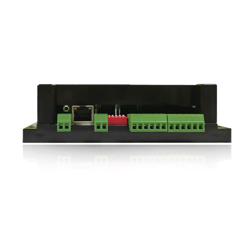
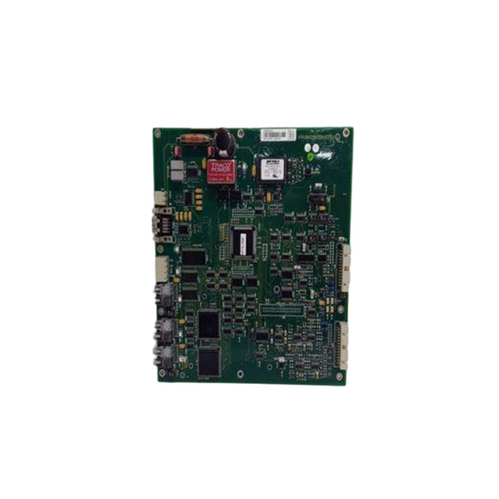
ABB UNS2980c-ZV4 digital I/O module

ABB UNS2980c-ZV4 is an advanced programmable logic controller (PLC) module designed for industrial automation applications. In the field of industrial automation, various devices and systems require reliable and efficient digital I/O modules to achieve signal acquisition and output in order to meet complex and changing control requirements. This module is an ideal choice for manufacturing and process control systems due to its outstanding performance, rich functionality, and high adaptability.

Key parameters of the product

Size specifications: Its external dimensions are 480 × 82 × 180mm. This size design ensures a reasonable layout of internal components, fully utilizes performance, and achieves efficient use of space as much as possible. Whether installed in compact control cabinets or in automated production line scenarios that require high equipment integration, it can be easily adapted without occupying too much valuable space.

input/output characteristic

​Digital Input/Output Points: This module supports up to 512 digital input and output points, making it easy to handle complex signal acquisition and control tasks in large-scale automation projects. Whether it is digital signal input from numerous sensors, limit switches, buttons and other devices on site, or control signal output from a large number of actuators, relays and other devices, it can be accurately processed to ensure the stable operation of the entire automation system.

Input voltage: The input voltage is 24V DC, which has wide applicability in common industrial DC power supply systems. It can ensure the stability of signal transmission and match the output signal voltage of most industrial field devices, reducing the risk of equipment failure caused by voltage incompatibility.

Output capability: The output voltage is 24V DC, and the maximum output current is 10A. With strong output driving capability, it can directly drive load devices such as small contactors and solenoid valves that require certain driving current, reducing intermediate relays and other conversion links, simplifying system wiring, and improving system reliability and response speed.

Adaptability to work environment

Temperature range: The working temperature range is -20 ° C to+60 ° C, and some data shows that it can withstand extreme temperatures from -40 ° C to 70 ° C. This means that the module can maintain a stable working state under various harsh temperature conditions such as high temperature industrial furnaces, hot outdoor environments, cold storage, high-altitude and low-temperature areas, and continuously provide reliable digital I/O functions for automation systems.

Other environmental tolerance: The module has good dust, moisture, and electromagnetic interference resistance capabilities. It adopts a sealed shell design and electromagnetic shielding technology, effectively blocking dust and moisture from entering the internal circuit. At the same time, it can resist the interference of complex electromagnetic environments around it, ensuring normal operation in high electromagnetic interference industrial environments such as steel smelting and chemical production.

Communication capability: Supports multiple communication protocols such as Modbus, Profibus, Ethernet/IP, which enables seamless communication and connection with different brands and types of control systems and smart devices. Both traditional industrial automation networks and emerging industrial Ethernet architectures can be easily integrated to achieve rapid data exchange and sharing, laying a solid foundation for building intelligent and integrated industrial automation systems.

Memory configuration: It has 1MB of flash memory and 256KB of random access memory (RAM). Sufficient flash memory is used to store important data such as control programs and system configuration parameters written by users, ensuring that data is not lost after the device is powered off; A moderate amount of RAM provides temporary space for data processing and variable storage during program execution, ensuring that the program can run efficiently and stably.

Power consumption: The maximum power consumption is 10W, which meets the requirements of powerful functions while maintaining a low energy consumption level, in line with the pursuit of energy conservation and environmental protection in today’s industrial field, and helps to reduce the operating costs and energy consumption of enterprises.

Performance advantages

High flexibility and scalability: The module supports a wide range of digital input and output points, and can be flexibly expanded or combined according to actual project requirements. In the upgrade and renovation project of the automated production line, if the original system has insufficient digital I/O points, the UNS2980c-ZV4 module can be easily added without the need for large-scale redesign and wiring of the entire control system, greatly saving time and cost, and easily adapting to constantly changing production processes and control requirements.

Excellent reliability: In terms of hardware design, high-quality electronic components are selected and rigorously screened and aged to ensure the stability of each component during long-term operation; At the software level, it has a comprehensive self diagnostic function and fault tolerance mechanism, which can monitor its own working status in real time. Once an abnormality is detected, corresponding measures are taken immediately for processing, such as automatic switching of backup channels, issuing fault alarm signals, etc., to ensure the uninterrupted operation of the system. In continuous production chemical enterprises, even if a temporary failure occurs in one input channel, the module can automatically switch to the backup channel to ensure that the production process is not affected and avoid huge economic losses caused by equipment shutdown.

Easy to integrate and use: With support for multiple mainstream communication protocols, it can quickly integrate with existing industrial automation systems. During the project implementation process, engineers do not need to spend a lot of time on complex communication interface development and debugging work, which can significantly shorten the project implementation cycle. At the same time, its operating interface is simple and clear, and the programming method complies with the IEC 61131-3 standard, making it easy for engineers to understand and master, reducing the threshold for use. Even relatively inexperienced technicians can quickly get started, configure modules, and write programs.

DAM0606 Industrial I / O module-Beijing Juying Hover Electronics Co., Ltd.

ABB UNS0874A Digital I/O Card

ABB UNS0874A Digital I/O Card

Product overview

ABB UNS0874A is a high-performance digital I/O card specifically designed for industrial automation systems. In the field of industrial automation, digital I/O cards act as the “nerve endings” of the system, undertaking critical tasks of signal input and output. ABB UNS0874A, with its excellent performance, can accurately and efficiently collect digital signals and send control instructions, and operate stably in various complex industrial environments, providing solid guarantees for the reliable operation of industrial automation systems. From the perspective of product type, it belongs to the category of digital I/O cards, which are highly compatible with ABB PLC systems in design and can be easily integrated into ABB automation systems. At the same time, it has standard industrial interfaces and can seamlessly connect with other components within the control system, ensuring smooth data transmission and interaction. Its exquisite exterior design measures 12.7 × 7.6 × 12.7cm and weighs only 0.3kg. This compact and lightweight design allows it to be installed into existing systems without requiring significant adjustments to the spatial layout or additional support structures, making it convenient and fast.

Brand background

ABB, as a globally renowned leader in the fields of power and automation technology, has a long history of over 130 years. Throughout its long development journey, ABB has always been committed to technological innovation and breakthroughs, accumulating profound technical expertise and rich practical experience in multiple fields such as energy management and industrial automation. Its business covers over 100 countries and regions worldwide, serving customers from various industries. With reliable product quality, advanced technology, and high-quality service, it has established an excellent brand reputation worldwide. In the research and development of industrial automation products, ABB has invested a lot of resources and continuously launched innovative products to meet the needs of global industrial enterprises for efficient, intelligent, and reliable automation solutions. ABB’s UNS0874A digital I/O card is one of its many excellent products, embodying ABB’s advanced technology and profound understanding of industrial automation.

Specification parameters

Signal type: Supports standard 24V DC digital signal input and output. This widely used signal type enables the digital I/O card to be compatible with the vast majority of industrial equipment on the market, making it easy to access whether building new systems or retrofitting old systems.

Electrical characteristics: When the input impedance reaches [specific value], it can effectively reduce signal interference and ensure the accuracy of the input signal; The output driving capability is [specific value], which can stably drive various loads and ensure reliable transmission of output signals. At the same time, it has overvoltage and overcurrent protection functions. When abnormal voltage or current occurs, the circuit can be automatically cut off to protect the card and connected equipment from damage.

Communication Interface: Equipped with standard communication interfaces such as RS-485, Ethernet, etc., supporting communication protocols such as Modbus, Profinet, etc., it can easily communicate data with the upper computer and other intelligent devices to achieve remote monitoring and control. When connected to the upper computer through an Ethernet interface, the data transmission rate can reach [specific rate value], ensuring fast and stable data transmission.

Working environment parameters: The working temperature range is [-20 ℃ -60 ℃], which can adapt to various complex temperature environments such as high-temperature workshops and cold outdoor environments; The humidity range is [5% -95% without condensation], and it can work normally in humid industrial environments such as food processing workshops, textile factories, etc

Core functions

Signal acquisition and processing: It can quickly and accurately collect digital signals from external devices, such as the position of objects detected by sensors, the operating status of devices, and convert them into digital quantities that the system can recognize. At the same time, the collected signals are filtered, denoised, and processed to remove interference signals, ensuring the accuracy and stability of the input signal and providing reliable basis for subsequent control decisions.

Control instruction output: Based on the system’s control logic and received control signals, the corresponding control instructions are output in the form of digital signals to the executing equipment, such as controlling the opening and closing of relays to start and stop motors, controlling the on-off of solenoid valves to control the flow of liquids or gases, etc., to achieve precise control of industrial equipment.

Status monitoring and feedback: Real time monitoring of the status of input and output channels, providing feedback on the channel’s working status to the upper computer through indicator lights or communication interfaces, such as whether the signal is input normally and whether the output is successfully executed. Once a fault is detected in the channel (such as signal loss, short circuit, etc.), an alarm signal can be promptly issued to facilitate maintenance personnel to quickly locate and troubleshoot the fault, ensuring the continuous and stable operation of the system.

Flexible configuration function: Supports flexible configuration of input and output channels through software or hardware settings. Users can set channels to different working modes according to actual application needs, such as normally open, normally closed, pulse input and output, to meet diverse industrial control requirements. In different production processes, channel configuration can be quickly adjusted according to specific requirements to improve the adaptability and flexibility of the system.

Working principle

Input working principle: When an external device (such as a sensor) generates a digital signal, the signal is transmitted to the ABB UNS0874A digital I/O card through the input channel. The input channel first electrically isolates the signal to prevent external interference signals from entering the internal circuit of the card. At the same time, the signal undergoes level conversion to convert it into a standard level signal that can be processed internally by the card. After isolation and conversion, the signal enters the input buffer, which buffers and preprocesses the signal before transmitting it to the data processing unit. The data processing unit analyzes and judges the received signal, removes interference signals, determines the logical state of the signal (high or low), and stores the processed signal in the input data register, waiting for the system to read.

Output working principle: When the system needs to send control instructions to external executing devices (such as relays, solenoid valves), the control signal is first written in digital form into the output data register. The signal in the output data register is processed and converted by the data processing unit into a signal form suitable for driving external loads. Then the signal is transmitted to the output driver, which amplifies the signal to meet the driving requirements of external loads. The amplified signal is transmitted to the external execution device through the output channel to control the device’s actions. At the same time, the output channel also has electrical isolation function to prevent the internal circuit of the card from being affected by electrical interference from external loads.

Key advantages

Excellent compatibility: Deeply compatible with ABB PLC systems, seamlessly integrated into ABB automation systems, ensuring overall system stability and collaborative efficiency. Meanwhile, due to its standard industrial interface and support for multiple communication protocols, it can be easily integrated with control system components and smart devices from other brands, providing users with greater flexibility in system construction and expansion. In the upgrading and transformation of industrial automation systems, there is no need to replace the entire control system. Simply connect the ABB UNS0874A digital I/O card to achieve functional expansion and performance improvement.

High reliability and stability: The sturdy structure can withstand harsh industrial environments and operate stably under harsh conditions such as high temperature, humidity, and strong electromagnetic interference. Equipped with comprehensive electrical protection functions such as overvoltage, overcurrent, and short-circuit protection, it effectively reduces the failure rate of card components in complex industrial environments, ensures the reliable operation of equipment, reduces production interruption time caused by equipment failures, lowers maintenance costs, and improves production efficiency. In harsh industrial environments such as steel smelting and chemical production, it can work stably for a long time to ensure the continuity of the production process.

Powerful scalability and flexibility: With a rich number of input and output points and flexible channel configuration functions, it can easily adapt to different production process requirements and subsequent system expansion. Whether it is a simple single machine control task or a complex large-scale automated production line control, it can meet the requirements through reasonable configuration. When an enterprise expands its production scale or adjusts its production process, there is no need to replace hardware equipment. The expansion and optimization of system functions can be achieved through software configuration alone, saving costs for the enterprise and improving production flexibility and adaptability.

Strict quality certification: We follow strict international safety and quality standards in our design, and have passed multiple authoritative certifications such as CE, UL, CSA, and ROHS to ensure that our products comply with international standards in terms of quality, safety performance, and other aspects. Users can use them with confidence. These certifications not only recognize product quality, but also provide guarantees for the wide application of products worldwide. Whether in domestic or international markets, they can meet the requirements of different users for product quality and safety.

Precautions

Installation precautions: When installing ABB UNS0874A digital I/O card, make sure the system is in a power-off state to avoid electric shock accidents or electrical damage to the card during installation. The installation location should be chosen in a well ventilated, dry, and non violent vibration area to ensure the normal heat dissipation and stable operation of the card components. During the installation process, handle with care to avoid physical damage to the card components. At the same time, ensure that the card components are tightly connected to the slot to prevent poor contact and abnormal signal transmission.

Wiring precautions: Before wiring, carefully read the product manual to clarify the wiring methods and signal type requirements for input and output channels. Use cables that meet specifications for wiring to ensure good insulation performance and prevent short circuits and leakage accidents. When wiring, ensure that the cable is firmly connected to avoid signal loss or increased contact resistance caused by looseness. For the input channel, it is important to ensure that the signal polarity of the sensor is consistent with the polarity of the card input channel; For output channels, appropriate cables and wiring methods should be selected based on the rated voltage and current of the executing device to prevent damage to the card or executing device due to overload.

Environmental precautions for use: Although this digital I/O card has strong environmental adaptability, it is still necessary to avoid using it under conditions that exceed its specified working environment parameters. To avoid prolonged operation in environments with temperatures exceeding 60 ℃ or humidity greater than 95% and condensation, and to prevent damage to the internal circuit of the card due to high temperature and humidity. At the same time, it is necessary to stay away from strong electromagnetic interference sources, such as large motors, transformers, etc., to avoid interfering with the normal operation of the card and affecting the accuracy of signal acquisition and output.

Maintenance precautions: Regularly inspect and maintain the card components, check whether the appearance of the card components is damaged, whether the wiring is loose, and whether the indicator lights are displaying normally. Regularly clean the dust on the surface of the card, keep the card clean, and prevent dust accumulation from affecting heat dissipation and electrical performance. When a card component malfunctions, the fault type should be determined based on the fault symptoms and indicator light status. Under the premise of ensuring safety, the fault should be investigated and repaired according to the guidance of the product manual. If it cannot be repaired by oneself, one should promptly contact ABB’s official technical support or professional maintenance personnel for repair.

Similar model supplement

ABB UNS0873A: It belongs to the ABB digital I/O card series with UNS0874A, and has certain similarities in functionality and application scenarios. However, the input and output points of UNS0873A are relatively small, making it suitable for industrial control scenarios with low requirements for I/O points and small system scales, such as automation transformation of small equipment and simple single machine control systems. In terms of cost, due to its relatively simple hardware configuration and lower price compared to UNS0874A, it is a good choice for users with limited budget and basic control requirements.

Siemens SM 321/322: As an important brand in the field of industrial automation, Siemens’ SM 321 (digital input module) and SM 322 (digital output module) are also widely used in the market. Compared with ABB UNS0874A, these two modules from Siemens focus more on communication protocols with Siemens’ own S7 series PLC system, and have excellent compatibility in the Siemens control system ecosystem. But when integrating with other brand systems, more setup and debugging work may be required. In terms of performance parameters, such as input/output response time, driving capability, etc., UNS0874A has its own advantages and disadvantages. Users can choose based on specific system requirements and existing equipment brands.

HIMA HIMATrix F3 DIO 8/8 01: This digital I/O module adopts a compact metal shell design, with 8 digital input and 8 digital output channels, supporting 24V DC signals. It performs outstandingly in terms of safety integrity level, complies with IEC 61508 SIL 3 certification, and is suitable for critical application scenarios with extremely high safety requirements such as emergency stop systems (ESD), fire and gas detection systems (F&G), etc. Compared with ABB UNS0874A, HIMA HIMATrix F3 DIO 8/8 01 is more professional and powerful in terms of safety functions, but may be slightly inferior to UNS0874A in terms of generality and ease of integration with non safety related industrial automation systems.

NI USB-6003 多功能I/O模块

ABB 5SHY3545L0005 Commutated Thyristor

Product overview

ABB 5SHY3545L0005 belongs to the asymmetric integrated gate commutated thyristor product series and is a power electronic device that integrates cutting-edge technology and excellent performance. By adopting patented free floating silicon technology, the internal electronic transmission path of the thyristor has been optimized, thereby improving overall performance and reliability; Paired with patented low inductance packaging technology, it effectively reduces energy loss and electromagnetic interference in the circuit, providing strong support for the stable operation of the equipment.

Brand background

ABB Group was formed in 1988 by the merger of ASEA from Sweden and BBC Brown Boveri from Switzerland, both of which have a history of over a century. ABB has always held a leading position in the fields of power and automation technology. ABB has created many industry firsts, such as the world’s first three-phase power transmission system, the first self cooling transformer, high-voltage direct current transmission technology, and the first electric industrial robot, and has been the first to put them into commercial use, with an extremely wide product line.

Specification parameters

On state loss: extremely low, with minimal energy consumption in the conducting state, effectively reducing system operating costs and improving energy utilization efficiency.

Trigger and feedback: Supports light triggered input, with precise and fast trigger signals that are not affected by electromagnetic interference; Equipped with status feedback function, it facilitates real-time monitoring of the system’s working status.

Response characteristics: With fast response and precise timing, it can quickly and accurately respond to rapidly changing current, voltage signals, and complex circuit control scenarios.

Power input: Supports AC square wave or DC power input, can adapt to various power systems, and expand the application range.

Core functions

Efficient power control: By relying on low-pass losses, energy losses are reduced during power transmission and conversion processes, ensuring efficient utilization of power. It is suitable for applications that require extremely high power stability and efficiency.

Accurate triggering and state monitoring: Light triggered input ensures that thyristors conduct and turn off at accurate times, and state feedback enables the system to detect and handle anomalies in a timely manner, improving the reliability and stability of the entire power electronic system.

Flexible power supply adaptation: It can be connected to AC square wave or DC power supply to meet the diverse power supply needs of different industries and devices, enhancing the universality and applicability of the product.

Working principle

Asymmetric integrated gate commutated thyristors combine the characteristics of thyristors and transistors. During the conduction stage, the gate receives a light trigger signal to quickly conduct the thyristor, allowing current to flow smoothly. When shutdown is required, integrated gate control technology is used to change the conduction state of internal electrons and achieve rapid shutdown. The patented free floating silicon technology optimizes the movement path of electrons inside the device, improving the efficiency of conduction and turn off; Low inductance packaging technology reduces energy loss and electromagnetic interference caused by inductance, ensuring stability during operation.

Precautions

Installation environment: It should be installed in a dry and well ventilated environment, avoiding damp, dusty, and strong electromagnetic interference places to prevent affecting the performance and service life of the device.

Electrical connection: When connecting circuits, it is important to ensure that the wiring is secure to avoid loose connections that may cause poor contact, heating, or even malfunctions. At the same time, it is necessary to strictly match electrical parameters according to product specifications to prevent overload operation.

Trigger signal: The transmission line of the light trigger signal should be kept intact, avoiding bending and damage, ensuring stable transmission of the trigger signal, and ensuring the normal operation of the thyristor.

ABB GVC736BE101 3BHB019719R0101 ACS 6000 IGCT - 雄霸工业

ABB 5SHY3545L0003 Advanced Voltage Protection Module

Product overview

1. Model and positioning

The ABB 5SHY3545L0003 advanced voltage protection module is a core protection device designed specifically for high-voltage power systems, aiming to provide comprehensive and accurate voltage protection and monitoring functions for power equipment. This module, with advanced digital signal processing technology and intelligent algorithms, can quickly respond to abnormal voltage changes and effectively prevent damage to power equipment caused by overvoltage, undervoltage, voltage imbalance, and other issues. It is widely used in substations, high-voltage transmission lines, large-scale industrial electrical equipment, and other scenarios, and is a key equipment to ensure the safe and stable operation of the power system.

2. Core values

High precision protection: With high-precision voltage detection and analysis capabilities, it can accurately capture subtle voltage fluctuations, quickly trigger protection actions, and reduce the risk of equipment damage due to abnormal voltage.

Intelligent adaptive: Built in intelligent algorithms can automatically adjust protection parameters according to the operating status of the power system, adapt to voltage protection requirements under different working conditions, and improve the reliability and flexibility of protection.

Multi functional integration: integrating voltage monitoring, fault diagnosis, protection control, data recording and communication functions, providing comprehensive support for power system operation and maintenance, reducing equipment quantity and system complexity.

High reliability design: Using high-quality electronic components and strict manufacturing processes, it has excellent anti electromagnetic interference, high temperature resistance, moisture resistance and other properties, and can operate stably in harsh environments, reducing maintenance costs and equipment downtime.

Core technical principles

1. High precision voltage sampling technology

The module adopts high-precision voltage transformer (PT) and 24 bit high-speed ADC (analog-to-digital converter) to sample the input voltage signal in real time, with a sampling frequency of up to 10kHz. It can accurately capture the transient changes of the voltage signal, ensuring a voltage measurement accuracy of ± 0.2%, and providing reliable data basis for accurate protection judgment.

2. Intelligent protection algorithm

Based on digital signal processing (DSP) technology and advanced intelligent algorithms, the sampled voltage data is quickly analyzed and processed. Built in multiple protection logics, including overvoltage protection, undervoltage protection, voltage imbalance protection, voltage harmonic protection, etc. By using the Fourier Transform (FFT) algorithm for frequency spectrum analysis of voltage signals, the harmonic content and frequency components of voltage can be identified. When voltage anomalies are detected, combined with preset protection thresholds and delay logic, the fault type can be quickly and accurately determined, and corresponding protection actions can be triggered.

3. Communication and Data Interaction

Supports multiple industrial communication protocols, such as IEC 61850, Modbus TCP/RTU, Profibus DP, etc., enabling seamless communication with substation automation systems (SAS), power monitoring systems (SCADA), and more. Real time uploading of voltage monitoring data, protection action information, fault recording data, etc. to the monitoring center, while receiving control instructions and parameter configuration information from the upper computer, achieving remote monitoring and management.

Core technical parameters

rated voltage

AC 100V/220V (voltage input), DC 24V/110V/220V (power input, ± 15% fluctuation adaptation)

Voltage measurement range

0-1.5 times rated voltage, accuracy ± 0.2%

Protection function

-Overvoltage protection: action value 50-150% Un, action time adjustable from 10ms to 5s – Undervoltage protection: action value 30-90% Un, action time adjustable from 10ms to 5s – Voltage imbalance protection: imbalance threshold value adjustable from 1-15%, action time adjustable from 100ms to 10s – Voltage harmonic protection: 2-50th harmonic threshold can be set, action time adjustable from 100ms to 30s

communication interface

-Ethernet: 10/100Mbps (supports IEC 61850, Modbus TCP) – Serial port: RS485 (supports Modbus RTU, Profibus DP) – Fiber optic interface: optional, supports optical signal transmission, enhances anti-interference ability

data record

Support the storage of the last 1000 event records, including protection action events, voltage limit events, device self-test events, etc; Supports fault recording data storage for up to 10 seconds, with a sampling frequency of 10kHz

work environment

-Temperature: -40 ℃ -+70 ℃ (fanless self cooling) – Humidity: 5% -95% (non condensing) – Protection level: IP20 (panel installation), in compliance with IEC 61000-6-2 industrial electromagnetic compatibility standard

power consumption

≤ 15W (unloaded)

Core functions

1. Comprehensive voltage protection

Overvoltage protection: When the system voltage exceeds the set overvoltage threshold, the protection is quickly triggered according to the preset action time, and the fault circuit is cut off by outputting a trip signal to prevent serious accidents such as insulation damage, shortened service life, and even fire caused by overvoltage in electrical equipment.

Undervoltage protection: When the system voltage is lower than the undervoltage set value, timely judgment and protective measures should be taken to avoid problems such as motor stalling and equipment malfunction caused by undervoltage, ensuring the safe and reliable operation of power equipment.

Voltage imbalance protection: Real time monitoring of the imbalance of three-phase voltage. When the voltage imbalance exceeds the set threshold value, an alarm signal is quickly issued and a trip can be triggered as needed to prevent motor overheating, damage, and other faults caused by three-phase voltage imbalance.

Voltage Harmonic Protection: Monitor and analyze voltage harmonics in the power grid. When the content of a specific harmonic exceeds the allowable threshold, initiate protection actions to reduce the interference and damage of harmonics to power equipment and improve power quality.

2. Intelligent fault diagnosis

Built in powerful fault diagnosis system, through continuous monitoring and analysis of voltage signals, can not only accurately determine the type of voltage abnormal fault, but also perform real-time self inspection on the hardware status of the module itself. Once internal circuit faults, communication abnormalities, power failures, and other issues are detected, a fault alarm signal will be immediately issued, and detailed fault information will be uploaded to the monitoring system, making it convenient for operation and maintenance personnel to quickly locate the fault point and shorten the troubleshooting time.

3. Data monitoring and recording

Real time monitoring and recording of key parameters such as amplitude, frequency, phase, and harmonic content of system voltage, ensuring data accuracy and completeness through high-precision and high-frequency sampling methods. Classify and store monitoring data, protection action events, fault recording data, etc., support local storage and remote transmission, and provide rich data support for the operation analysis, fault tracing, and optimization design of the power system.

4. Remote communication and control

Stable and high-speed data exchange can be achieved with the power monitoring system through multiple communication interfaces. Operation and maintenance personnel can remotely view module operation status, real-time voltage data, protection parameter settings, and other information from the monitoring center. At the same time, it supports remote modification of protection thresholds, action times, and other parameters, as well as remote switching of protection functions, to achieve flexible control and management of protection modules and improve the efficiency of power system operation and maintenance.

Typical application scenarios

1. Substation protection

In substations, the 5SHY3545L0003 advanced voltage protection module can be installed at key locations such as high-voltage busbars and transformer inlet/outlet sides to comprehensively monitor and protect the voltage inside the substation. When the system experiences overvoltage, undervoltage and other faults, quickly cut off the faulty circuit to prevent the spread of faults, ensure the safe operation of electrical equipment in the substation, and maintain stable power supply of the power system. At the same time, by communicating with the substation automation system, voltage data and protection information are uploaded to the monitoring backend to achieve intelligent operation and management of the substation.

2. Protection of high-voltage transmission lines

Applied to high-voltage transmission lines, real-time monitoring of line voltage status, timely detection of voltage anomalies caused by lightning strikes, short circuits, wire breaks, and other faults. When a fault occurs, quickly trigger protection actions, isolate the faulty line, reduce the scope and duration of power outages, and improve the reliability and stability of the transmission line. In addition, by recording the voltage waveform and data before and after the fault, it provides important basis for line fault analysis and repair.

3. Protection of large industrial electrical equipment

For large industrial electrical equipment in industries such as steel, chemical, mining, etc., such as large motors, frequency converters, electric arc furnaces, etc., this protection module can effectively protect the equipment from the impact of abnormal voltage. Real time monitoring of voltage changes during motor start-up and operation to prevent motor damage caused by voltage fluctuations; Installed on the input side of the frequency converter, it protects the frequency converter from the impact of high or low voltage, ensures the continuity and stability of industrial production, and reduces equipment maintenance costs and production losses.

4. New energy grid connection protection

In the grid connection process of new energy generation systems such as wind power and photovoltaic, the 5SHY3545L0003 module can monitor the voltage quality of the grid connection point, ensuring the safe and stable connection between the new energy generation system and the power grid. When there is abnormal voltage in the power grid or internal voltage fluctuations in the new energy generation system, timely protective measures should be taken to prevent adverse effects on the power grid, while ensuring the safe operation of the new energy generation equipment itself and improving the reliability and grid connection efficiency of new energy generation.

Key advantages

1. High precision and high reliability

Advanced voltage sampling technology and intelligent algorithms ensure high accuracy in voltage measurement and protection judgment, and can accurately identify small voltage abnormal changes. Using high-quality components and strict production processes, after extensive environmental testing and reliability verification, it has excellent anti-interference ability and environmental adaptability. It can still operate stably and reliably in complex electromagnetic environments and harsh weather conditions, effectively reducing the probability of protection misoperation and refusal.

2. Flexible functional configuration and adaptability

Flexible configuration supporting multiple protection functions, users can customize protection thresholds, action times, protection logic and other parameters through human-machine interface or remote communication according to actual application scenarios and power system requirements. At the same time, the module has good compatibility and can be integrated with different brands and models of power equipment and monitoring systems, suitable for various sizes and types of power systems, meeting diverse voltage protection needs.

3. Efficient operation and maintenance support

The powerful data recording and communication functions provide strong support for the operation and maintenance of the power system. Detailed fault recording data and event records help to quickly locate the cause of the fault and shorten the time required for fault handling; The remote monitoring and parameter adjustment function reduces the workload of on-site operations and improves operational efficiency; The comprehensive self checking function and fault diagnosis capability enable operation and maintenance personnel to timely grasp the operation status of modules, detect potential problems in advance, achieve preventive maintenance, and reduce operation and maintenance costs.

4. Comply with industry standards and regulations

Strictly follow international and domestic standards in the power industry, such as IEC 61850, IEEE standards, etc., to ensure that product quality and performance meet industry requirements. Through multiple authoritative certifications, such as CE certification, UL certification, etc., we ensure the compliance and safety of our products worldwide, providing users with reliable voltage protection solutions.

ABB 5SXE06-0160 3BHB020720R0002 Module - 雄霸工业

ABB 5SHY35L4510 Asymmetric Integrated Gate

product overview

1. Model and positioning

Model name: ABB 5SHY35L4510 Asymmetric Integrated Gate Commutated Thyristor (abbreviated as Asymmetric IGCT). This product is designed specifically for high-voltage and high-power power electronics applications. With its unique asymmetric structure and advanced integrated gate control technology, it plays a key role in high-voltage direct current transmission (HVDC), flexible alternating current transmission systems (FACTS), high-power motor drives, and other fields. It is the core power semiconductor device for achieving efficient energy conversion and control.

2. Core values

Efficient power processing: With excellent high-voltage and high current blocking and conducting capabilities, it can significantly improve the power transmission efficiency of the power system.

Quick switch feature: It can achieve fast turn-on and turn off, effectively reducing switch losses and improving system dynamic response performance.

Reliability and stability: Adopting advanced manufacturing processes and strict quality control, it can still operate stably under harsh working conditions, extending the service life of the equipment.

Flexible application adaptation: The unique asymmetric design makes it suitable for various complex power electronic topologies, meeting the customized needs of different application scenarios.

Core technical principles

1. Asymmetric structural design

5SHY35L4510 adopts an asymmetric structure, and its forward blocking voltage and reverse blocking voltage capabilities are different. The forward direction can withstand voltages up to 4500V, while the reverse blocking ability is relatively low. This design allows the device to achieve unidirectional current flow in specific circuit topologies without the need for additional anti parallel diodes, simplifying the circuit structure, reducing costs and system complexity, and minimizing additional losses and parasitic parameter effects caused by anti parallel diodes.

2. Integrated Gate Converter Technology (IGCT)

The integrated gate commutated thyristor combines the high voltage and high current characteristics of thyristors with the fast switching capability of transistors. By applying precise control signals through the gate, the device can be quickly turned on and off. The gate drive circuit adopts low inductance design and high-speed signal transmission technology, which shortens the switching time of the device to the microsecond level, effectively reduces switching losses, and improves the operating frequency and efficiency of the system.

3、 Core technical parameters

Positive blocking voltage: 4500V

On state average current: 3500A

Surge current (10ms): 80 on state average current**

Surge current (10ms): 80kA

Opening time: ≤ 3 μ s

Off time: ≤ 15 μ s

Reverse blocking voltage: 80V

Working temperature range: -40 ℃~+125 ℃

Packaging form: pressure bonding packaging, with good heat dissipation and mechanical stability

Dv/dt tolerance: 500V/μ s (typical value)

Di/dt tolerance: 1000A/μ s (typical value)

Core functions

1. High voltage and high current control

In high-voltage direct current transmission systems, 5SHY35L4510 can accurately control the on/off and magnitude of direct current, achieving efficient transmission of long-distance and large capacity electrical energy. In high-power motor drive applications, the starting, speed regulation, and braking processes of the motor can be stably controlled, and the driving power can reach several megawatts, meeting the demand for high-power and high-precision driving in industrial production.

2. Efficient energy conversion

By virtue of its fast switching characteristics and low conduction loss, efficient AC-DC conversion, DC-DC boost/buck and other energy conversion functions are achieved in power electronic converters, increasing the energy conversion efficiency to over 98% and effectively reducing system energy consumption and operating costs.

3. Fault protection and system stability enhancement

Having high di/dt and dv/dt tolerance, it can quickly respond and cut off the fault current in case of short circuit, overvoltage and other faults in the system, prevent the spread of faults, and enhance the stability and reliability of the power system. At the same time, soft switching function is achieved through gate control, reducing voltage and current stress during the switching process, lowering electromagnetic interference (EMI), and improving the overall electromagnetic compatibility of the system.

4. Flexible topology adaptation

The asymmetric structure enables it to adapt to various power electronic topologies, such as three-phase bridge circuits, multilevel converter circuits, etc. In flexible AC transmission systems, it can be applied to devices such as Static Var Compensators (SVC) and Static Synchronous Compensators (STATCOM) to achieve fast reactive power compensation and voltage regulation, improving the power quality and stability of the AC power grid.

Typical application scenarios

1. High Voltage Direct Current Transmission (HVDC)

In long-distance high-voltage direct current transmission projects, 5SHY35L4510 serves as the core component of the converter valve, undertaking the task of converting AC and DC electrical energy. For example, in cross sea transmission and large-scale power allocation projects across regions, stable transmission of electricity at the level of thousands of kilometers and millions of kilowatts can be achieved, reducing transmission losses, improving energy utilization efficiency, and ensuring the reliability and stability of power supply.

2. Flexible AC Transmission System (FACTS)

Applied to devices such as Static Var Compensators (SVC) and Static Synchronous Compensators (STATCOM), it monitors real-time changes in grid voltage and reactive power, quickly adjusts reactive power output, stabilizes grid voltage, improves power quality, and enhances the transmission capacity and stability of the grid. Especially in scenarios with large fluctuations in power grid load and large-scale integration of new energy, it effectively alleviates the problems of voltage fluctuations and frequency offset in the power grid, and enhances the power grid’s ability to absorb new energy.

3. High power motor drive

In high-power motor drive systems in industries such as steel, mining, and shipbuilding, such as main drive motors for rolling mills, mining hoist motors, and ship propulsion motors, efficient speed regulation and precise control of motors are achieved. By precisely adjusting the input voltage and frequency of the motor, it can maintain the optimal operating state of the motor under different working conditions, improve production efficiency, reduce equipment energy consumption, and reduce mechanical shock during motor starting and braking processes, thereby extending the service life of the motor and transmission system.

4. New energy grid connection

In the grid connection stage of new energy generation systems such as wind power and photovoltaic, it is used in the inverter to achieve stable conversion and grid connection control of electrical energy. Being able to quickly respond to power fluctuations in new energy generation, achieve smooth connection with the power grid, improve the reliability and grid efficiency of new energy generation, and help build a clean and efficient energy system.

​Key advantages

1. High performance indicators

The high forward blocking voltage, large steady-state current, and fast switching characteristics make it perform excellently in high-voltage and high-power applications, meeting the stringent performance requirements of power systems. Compared with traditional thyristor devices, the power processing capacity is increased by more than 30%, and the switching loss is reduced by more than 20%.

2. High reliability and long lifespan

Adopting advanced chip manufacturing processes and packaging technologies, the chips are made of high-quality silicon materials and optimized doping processes to improve the voltage resistance and current carrying capacity of the devices; The packaging structure has good heat dissipation performance and mechanical strength, and can withstand vibration, impact, and temperature changes under harsh environmental conditions. After rigorous aging testing and reliability verification, the mean time between failures (MTBF) exceeds 100000 hours, reducing equipment maintenance costs and downtime.

3. Advantages of system integration

Asymmetric structure and integrated gate control technology simplify circuit design, reduce the number of peripheral devices, and lower system costs and volume. At the same time, we provide comprehensive solutions for driving and protection circuits, which facilitate integration with other power electronic devices and systems, shorten product development cycles, and improve system design efficiency.

4. Green and energy-saving

The low switching loss and conduction loss characteristics effectively reduce system energy consumption, which is in line with the development trend of green energy conservation. In large-scale applications, it can significantly reduce the energy consumption and carbon emissions of the power system, providing strong support for enterprises to achieve energy-saving and emission reduction goals.

Installation requirements

Environmental conditions: The installation environment should be kept dry, clean, and free of corrosive gases and dust. The ambient temperature should be controlled within the range of -40 ℃ to+50 ℃, and the relative humidity should not exceed 95% (without condensation).

Electrical connection: Strictly follow the electrical schematic for wiring, ensure correct connection of positive and negative poles, secure and reliable wiring terminals, and avoid loose connections causing poor contact and heating. At the same time, to reduce electromagnetic interference, the gate control signal line should use shielded cables and maintain an appropriate distance from the main circuit cable.

Heat dissipation design: The device needs to be installed on an efficient heat dissipation device, such as a radiator or water-cooled heat dissipation module. Apply uniform thermal grease between the device and the heat sink during installation to ensure good heat conduction. The heat dissipation capacity of the heat sink should meet the heat dissipation requirements of the device at maximum power consumption, ensuring that the operating junction temperature of the device does not exceed the rated value.

ABB 57160001-ACX DSDP 140B Counter Board

product overview

1. Model and positioning

Model name: ABB 57160001-ACX DSDP 140B Counting Board Product positioning: Industrial grade high-precision counting and measurement module, designed for automation control systems, supports multi-channel high-speed pulse counting, frequency measurement, and event triggering, suitable for motor speed monitoring, production line counting, energy metering and other scenarios, can accurately capture dynamic signals and provide real-time data output.

2. Core values

High precision measurement: supports nanosecond pulse resolution to meet precision counting requirements

Multi mode adaptation: compatible with multiple signal sources such as incremental encoders, proximity switches, sensors, etc

Industrial grade reliability: designed to resist electromagnetic interference and adapt to harsh industrial environments

Flexible configuration: Through software defined counting logic, support custom triggering conditions

Core functions

1. Multi channel counting capability

Number of channels: 4 independent counting channels (CH1-CH4), supporting differential/single ended input

Counting types: forward counting, reverse counting, bidirectional counting, frequency measurement (0-10MHz)

Input signal: 5V/24V TTL/CMOS level, supports incremental encoder A/B/Z phase (orthogonal decoding)

Count range: 32-bit unsigned integer (0-4294967295), supports overflow interrupt

2. High speed pulse processing

Maximum counting frequency: Single channel 10MHz (differential input)/5MHz (single ended input)

Edge detection: Rising edge/falling edge/double-sided edge triggering, trigger delay ≤ 50ns

Orthogonal decoding: supports 1x/2x/4x multiplier counting, suitable for high-precision encoder applications

3. Intelligent triggering and event response

Trigger modes: software trigger, external signal trigger, threshold comparison trigger

Event output: 8-channel digital output (DO), supporting event driven counting of arrivals, overflows, signal anomalies, etc

Synchronized clock: Supports IEEE 1588 precision timing, with multi board time synchronization error ≤ 1 μ s

4. Status monitoring and diagnosis

Real time monitoring: Real time display of channel signal status, counting rate, overflow times and other parameters

Fault diagnosis: Detection of abnormal input signals (disconnection, noise) and automatic generation of diagnostic reports

Data recording: Supports storing the logs of the last 1000 events (without loss in case of power failure)

Technical parameters

1. Hardware specifications

Processor: ARM Cortex-M4 32-bit processor (168MHz) with built-in floating point unit (FPU)

Memory configuration: 256KB Flash program storage+64KB SRAM data cache

Communication interface: Ethernet: 10/100Mbps (supports Modbus TCP, Profinet IO) – Serial port: RS485 (supports Profibus DP) – Expansion interface: SPI/I2C (for external module cascading)

Input characteristics

-Input impedance: 10k Ω (single ended)/100 Ω (differential) – Common mode rejection ratio: ≥ 60dB (50kHz)

Output characteristics: Digital output: 24V DC/0.5A (relay isolation) – Analog output: 4-20mA (optional module)

Working power supply: 24V DC (± 15%), power consumption ≤ 5W (no-load)

Environmental adaptability

Temperature: -40 ℃~+70 ℃ (without fan) – Humidity: 5%~95% (without condensation) – Protection level: IP20 (panel installation)

2. Software functions

Configuration tool: ABB Control Studio graphical programming software, supporting drag and drop logic configuration

Protocol support: Modbus RTU/TCP, Profinet, EtherCAT (firmware upgrade required)

Development Interface: Provides C++/Python SDK, supports third-party system integration

Working principle

Typical working mode

Encoder mode: Receive A/B/Z phase pulses, calculate speed (RPM), position (number of pulses), and steering (forward/reverse)

Frequency measurement mode: Measure the input signal frequency using the periodic/pulse method, with a resolution of 0.01Hz (1s sampling period)

Event counting mode: Count the number of external triggering events and support preset threshold alarms

Typical application scenarios

1. Motor speed monitoring system

Configuration: Connect 2 servo motor encoders (CH1/CH2) to a single counting board

Function:

Real time calculation of motor speed (accuracy ± 0.1RPM)

Speed over limit alarm (DO output driven sound and light alarm)

Historical speed curve storage (supports USB export)

2. Automated counting of production lines

Configuration: Connect 4 sensors to each of the 4 channels (counting product pass rates)

Function:

Multi channel independent counting, real-time display of production line output

Automatic triggering of packaging machine startup when production meets standards (event linkage)

Save current count status (power down memory) during abnormal shutdown

3. Energy metering and monitoring

Configuration: Connect the pulse output of the electric energy meter (1 pulse=1kWh)

Function:

Accumulated energy consumption statistics (supporting peak and valley time differentiation)

Power factor calculation (in conjunction with voltage and current signals)

Abnormal energy consumption alarm (triggering DO output when exceeding the preset threshold)

Key advantages

1. Technological leadership

High precision counting: nanosecond level edge detection technology, meeting the measurement needs of servo motors and precision encoders

Multi protocol compatibility: Supports mainstream industrial communication protocols, seamlessly integrates ABB and third-party control systems

Orthogonal decoding optimization: Built in hardware decoding circuit reduces CPU load and improves system real-time performance

2. Engineering convenience

Plug and play: supports hot swapping (channels need to be disabled first), module replacement does not require reconfiguration

Visual configuration: Use Control Studio to intuitively configure counting logic, reducing programming difficulty

Batch calibration: supports calibrating multiple devices at once through USB, improving engineering debugging efficiency

3. Reliability design

Electromagnetic compatibility: Compliant with IEC 61000-6-2 industrial anti-interference standard, suitable for strong interference environments such as frequency converters and welding machines

Redundant design: Dual backup of critical circuits (such as clock and power monitoring), automatically switching to backup channels in case of failure

Wide temperature operation: -40 ℃ low-temperature start-up technology, suitable for applications in northern cold regions and outdoor equipment

Installation and maintenance

1. Wiring specifications

Signal wiring: Use twisted pair shielded wires, and it is recommended to use differential input for encoder signals (to reduce common mode interference)

Grounding requirement: The module casing and system are grounded together, with a grounding resistance of ≤ 1 Ω

Power protection: Install surge protector at the input end (recommended ABB MS112-1.6)

2. Regular maintenance

Signal accuracy verification: 1 year, use a signal generator to input 1MHz pulses and verify that the counting error is ≤ 0.01%

Firmware upgrade: On demand/online upgrade through Control Studio, backup the current configuration file before upgrading

Wiring inspection: 6 months, check the torque of the terminal block screws (recommended 2.5N · m) to prevent poor contact

3. Fault handling

E001: Channel input exception

1. Check if the sensor wiring is loose

2. Measure whether the amplitude of the input signal meets the specifications

3. Change the channel for testing

E003: Communication timeout

1. Restart the module

2. Check IP address/baud rate configuration

3. Test the connectivity of communication cables

E005: Counter overflow

1. Check the counting range setting

2. Enable overflow interrupt auto reset function

3. Upgrade 32-bit extended counting mode

57160001-ACX - Automation Components and Parts for Industry

ABB  216VC62A  Numerical Generator Protection

ABB  216VC62A  Numerical Generator Protection

Features

• Modular hardware

• Selectable protection functions

• Multitude of applications

• Menu-assisted setting with PC

• Fully numerical signal processing

• Continuous self-monitoring of hardware

• Cyclical testing routines mostly performed by the software

• Setting of parameters and recording of the settings by PC

• Display of measured values

• Display of events, their acknowledgment and printout

• Disturbance recording

• Self-documentation

• Long-term stability

• Communication and coordination with station control

• Two design versions available; REG216 / REG216 Classic

Application

The REG216 is intended for the protection of generators and block transformers.

The modular hardware and software design allows an extremely flexible installation.

Simplicity of adaption to the size of the primary system and the desired protection schemes are achieved through the combination of a software library and hardware modules.

Economic solutions can thus be achieved in the full range of applications for which it is intended.

The REG216 software system offers a library of protective functions.

Functions suitable for generator and transformer protection are listed in the table below.

Different degrees of redundancy can be selected.

Availability and reliability of the protection can be chosen to suit the application by duplicating e.g. auxiliary supply units of the whole system.

Standard interfaces make REG216 compatible with different process control systems.

Data exchange with higher process control levels are possible, e.g. one-way reporting of digital states and events, measured values and protection parameters.

REG216 and REG216 Classic differ with regard to the binary process connection:REG216 uses the E/A-module 216GD61a.

The REG216 Classic uses the modules 216GE61 / 216GA61 and 216GA62.

Protection functions

All protection functions required for the stand-alone protection of generators, power transformers and feeders are available.

The system therefore replaces several relays of a conventional protection scheme for such power system equipment.

The table on page 2 gives a survey of the most significant protection functions.

The desired protection functions to suit the particular application can simply be selected from a comprehensive library using the personal computer. 

​No knowledge of computer programming is required.

All setting ranges are extremely wide to make the protection functions suitable for a multitude of applications.

The following main parameters can be set:

• Allocation of processing units

• Input channel or channels

• Pick-up setting

• Time delay

• Definition of the operating characteristic

• Tripping logic

• Control signal logic.

Setting a corresponding parameter enables the protection functions to be “connected” to particular input channels.

Digital input and output signals can also be internally combined logically:

• The tripping outputs of each protection function can be assigned to channels of the tripping auxiliary relay assembly in a manner corresponding to a matrix

• The pick-up and tripping signals can be assigned to the channels of the signalling auxiliary relay assembly.

• Provision is available for blocking each protection function with a digital signal

(e.g. digital inputs or by using the tripping signal of another protection function).

• External signals applied to the digital inputs can be processed in any desired fashion.

• Digital signals can be combined to perform logical functions e.g. 

External enabling or blocking signals with the output signals of an internal protection function and then used to block one of the other protection functions.

Remote in- and outputs (RIO580)

Using the process bus type MVB, remote in and output units 500RIO11 can be connected to the REG216 terminals.

The input and out put channels can be extended to a large number by using the RIO580 remote input/output system.

Installing 500RIO11 I/O units close to the process reduces the wiring dramati cally, since they are accessible via fibre optic link from the REG216 terminals.

Analog signals can also be connected to the system via the 500AXM11 from the RIO580

family:

• DC current 4…20 mA

0…20 mA-20…20 mA

• DC voltage 0…10 V-10…10 V

• Temp. sensor Pt100, Pt250, Pt1000,

Ni100, Ni250, Ni1000.

Hardware

The REG216 equipment comprises two main  assemblies which are physically separated from each other and linked by standard prefabricated screened cables:

• Interfaces to the primary system (CTs, PTs and auxiliary relays), which provide DC isolation and a barrier to electromagnetic interference

• Parallel bus and associated electronic units (e.g. analog inputs and data processors/ for signal conditioning and processing.

The complete protection scheme comprises relatively few hardware modules allowing subsequent expansion of electronic units and the interfaces. 21 units of rack space is avail able per equipment frame

Product overview

1. Model and positioning

Model name: ABB 216VC62A Digital Generator Protection Device Product positioning: A multifunctional digital protection and monitoring device designed specifically for medium and large generators, supporting full lifecycle protection of generators, suitable for scenarios such as thermal power, hydropower, gas power generation, and industrial self owned power plants. It can provide accurate fault detection, rapid protection actions, and comprehensive equipment status monitoring.

2. Core values

Triple protection system: integrated electrical quantity protection, non electrical quantity protection, and system level redundancy design

Digital technology: high-speed data processing based on microprocessors, supporting IEC 61850 communication, compatible with smart grid architecture

Flexible configuration: Through software defined protection logic, adapt to different types of generators (synchronous/asynchronous generators, rotating excitation/static excitation systems)

Core protection function

Non electrical quantity protection

Temperature monitoring: Supports 6-channel PT100/PT1000 winding temperature and bearing temperature input, temperature rise rate protection (5 ℃/min warning, 10 ℃/min trip)

Mechanical protection: vibration amplitude monitoring (4-20mA input), shaft displacement protection (± 2mm measurement range, accuracy 0.1% FS)

Process interlocking: Integrated with 3 process signal inputs (such as turbine trip, low lubricating oil pressure), supporting dual redundant interlocking of hard wiring and communication

Auxiliary functions

Wave recording and event recording: Supports 8-channel synchronous wave recording (sampling rate 1000Hz), stores the last 100 fault wave recordings (each lasting 10 seconds)

State monitoring: Real time calculation of generator power factor, efficiency, and winding thermal aging index (based on IEEE Std 120-2018 model)

Remote operation and maintenance: Built in web server, supporting real-time monitoring through mobile app (WiFi module optional)

Technical Parameter

1. Electrical parameters

Rated voltage: AC 100V/220V (voltage input), DC 24V/110V/220V (power input, ± 15% fluctuation adaptation)

Rated current: 5A/1A (current input, compatible with CT secondary side)

Frequency range: 45-65Hz

Protection accuracy: Current/voltage: ± 0.5% FS, frequency: ± 0.01Hz

Communication interface: 2 x IEC 61850-9-2 LE fiber optic interface, 1 x Modbus TCP/RTU, 1 x RS485 (supports Profibus DP)

2. Machinery and Environment

Dimensions: 19 inch rack mounted (482mm × 260mm × 180mm), 3U height

Installation method: panel installation/rail installation (optional bracket required)

Working temperature: -40 ℃~+70 ℃ (no fan self cooling), humidity 5%~95% (no condensation)

Protection level: IP40 (front panel), compliant with IEC 61000-6-2 industrial electromagnetic compatibility standard

Working principle

Data Collection Layer

Sensor access: Collect voltage/current transformer signals through high-precision ADC (24 bits), supporting Roche coil/traditional CT/PT

Synchronization timing: Supports IEEE 1588v2 precision timing (accuracy ≤ 1 μ s) to ensure synchronization of waveform data between multiple devices

Execution Layer

Trip output: 8 independent trip contacts (configurable for hold/pulse mode), supporting trip signal self hold (requiring external reset)

Warning output: 4-channel warning contacts (such as overload warning, high temperature), contact capacity 24VDC/2A

Typical application scenarios

1. Protection scheme for thermal power generators

Configuration: Single 216VC62A device+redundant CT/PT circuit

Core functions:

Generator outlet circuit breaker failure protection (in conjunction with busbar protection device)

Rotor grounding protection (injection type DC detection, grounding resistance measurement range 0.1k Ω~10M Ω)

Plant power switching interlock (real-time communication with fast switching device, switching time ≤ 80ms)

2. Protection scheme for hydroelectric generators

Special Features:

Turbine overspeed protection (redundant judgment of two out of three speed signals, adjustable operating speed from 115% to 150% of rated speed)

Low frequency oscillation suppression (PSS power oscillation damper, phase compensation range ± 180 °)

Non full phase protection (supports inconsistent detection of 2-phase/3-phase circuit breakers, action time ≤ 50ms)

Key advantages

1. Technological leadership

High speed processing platform: using ARM Cortex-A9 dual core processor (400MHz), protecting logic operation cycle ≤ 1ms

Adaptive algorithm: dynamically adjust protection settings based on real-time parameters of the generator (such as load and temperature) to avoid misoperation/refusal to operate

2. Engineering convenience

One click tuning tool: ABB Relion ®  The Manager software automatically generates protection settings (enter the generator nameplate parameters)

Plug and play design: supports hot swapping (requires power to be disconnected first), automatically loads configuration files after module replacement (via SD card)

3. Reliability design

Triple redundancy: CPU redundancy+power redundancy+communication redundancy (redundant modules need to be selected)

Fault self diagnosis: Real time monitoring of internal temperature, memory verification, clock synchronization status of the device, self diagnosis cycle of 100ms

ABB 3ASC25H203-12 DAPC 100-12; Control board

ABB 3ASC25H203-12 DAPC 100-12; Control board, with CMT memory stick

Additional Information

ABB Type Designation: DAPC 100-57

Country of Origin: Sweden (SE)

Customs Tariff Number: 85371098

Gross Weight: 0.37 kg

Invoice Description: Control board, with CMT memory stick

Made To Order: No

Minimum Order Quantity: 1 piece

Order Multiple: 1 piece

Package Level 1 Units: 0 carton

Part Type: New

Product Name: Control board, with CMT memory stic

Product Net Weight: 0.37 kg

Quote Only: No

Selling Unit of Measure: piece

ABB 3ASC25H203-12 DAPC 100-12; Control board, with CMT memory stic

Product Definition and Positioning

Model name: ABB 3ASC25H203-12 DAPC 100-12 Control Board (including CMT Memory Stick) Product positioning: Industrial automation core control unit, integrated CMT (Compact Memory Technology) memory stick, designed specifically for mid to high end industrial control systems, supporting complex logic control, real-time data processing, and convenient program management, suitable for industrial scenarios that require high reliability and flexible configuration.

CMT Memory Stick Core Features

1. Hardware level data carrier

Storage capacity: comes standard with 8GB industrial grade flash memory and supports up to 32GB expansion

Interface type: Dedicated high-speed interface, data read/write speed up to 15MB/s (read)/8MB/s (write)

Security features:

Hardware Encryption: AES-128 Data Encryption Protection

Anti misoperation: plug-in interface with mechanical locking device

Seismic design: comply with IEC 60068-2-6 vibration standard

2. System level functional integration

Program loading: Supports offline configuration file import/export, complete system program migration within 5 minutes

Firmware upgrade: Control board firmware version iteration through memory stick, supporting breakpoint resume function

Data backup: Automatic periodic backup of key parameters (such as PID control parameters, equipment calibration values)

Core technical parameters

1. Hardware specifications of control board

Processor: Freescale PowerPC MPC5553, with a clock speed of 400MHz, supporting floating-point arithmetic units (FPUs)

Memory configuration: 256MB DDR3 cache+1GB NAND Flash (onboard)+CMT memory stick expansion storage

Communication interface: Ethernet: 2 × 10/100Mbps (supports Modbus TCP, EtherNet/IP) 

Serial port: 3 × RS485/RS232 (supports Profibus DP) – Other: CAN 2.0B, USB 2.0 (only for CMT memory sticks)

I/O channel: Analog input: 8 × 16 bits (± 10V/4-20mA, supports cold end compensation)

Analog output: 4 × 16 bits (± 10V/4-20mA) – Digital input/output: 16 × 24V DC (optically isolated)

Working power supply: 24V DC (± 15%), power consumption ≤ 15W (including CMT memory stick)

Environmental adaptability: Temperature: -40 ℃~+70 ℃ (without cooling fan) 

Humidity: 5%~95% (without condensation) – Protection level: IP20 (panel installation), 

in compliance with IEC 61000-6-2 electromagnetic compatibility standard

2. Software functional parameters

Operating system: QNX Neutrino real-time operating system (RTOS), task scheduling accuracy ≤ 10 μ s

Programming support:

Compliant with IEC 61131-3 standards (LD/LAD, ST, FBD, SFC)

Support ABB Control Builder M engineering tool, compatible with third-party OPC UA servers

Data processing: Supports real-time data acquisition through 100+channels, with a minimum control cycle of 500 μ s

​Core Control Function Architecture

CMT Memory Stick Workflow

Program deployment: Download the compiled control program to CMT memory stick through Control Builder M

System startup: After the control board is powered on, it automatically reads the configuration files (. cfg) and program files (. app) from the memory stick

Data exchange: Real time data during operation is synchronized to the memory stick according to the set cycle (1s~10min)

Fault recovery: When a system abnormality is detected, the latest valid backup data in the memory stick is automatically called up

Typical application scheme

Coordinated Control of Thermal Power Turbine

Configuration: Redundant deployment of 3 control boards, CMT memory sticks storing turbine start stop curves and load distribution strategies

Function:

Real time adjustment of valve opening (control accuracy ± 0.5%)

Memory stick automatic backup of PID parameters under variable load conditions

Support online modification of control strategies (through memory stick hot update program)

Intelligent warehousing and logistics system

Configuration: Single control board with dual CMT memory sticks (primary and backup redundancy)

Function:

Multi axis motion control (supporting 32 axis synchronization)

Memory stick stores coordinate data of each storage location and equipment calibration parameters

Quickly restore sorting system configuration through memory stick in case of malfunction

Installation and Maintenance Guide

1. CMT Memory Stick Operation Specification

Insertion/extraction: Be sure to operate in the power-off state, and hearing a “click” sound when inserting indicates that it is in place

Data backup: It is recommended to perform full backup through ABB Memory Tool software every week

Compatibility: Only supports ABB original CMT memory stick (part number: 3ASC25H205-01), third-party storage devices may cause system failure

2. Typical fault codes

E0101: CMT memory stick not recognized, check if the memory stick is securely inserted, restart the control board

E0203: Program checksum error, re download program to memory stick and restart system

E0315: Insufficient memory stick storage space, deleting outdated log files or replacing with a larger capacity memory stick

Industry standards and certifications

Electrical safety: compliant with IEC 61010-1 (pollution level 3)

Electromagnetic compatibility: EN 61326-1 (Class A for industrial environments)

Functional safety: Supports SIL 2 safety control (requires safety software package)

ABB DAPC100 3ASC25H203 control board Reasonable price - SAUL ELECTRIC

ABB DSQC545A 3HAB8101-19/07E servo drive power module

ABB DSQC545A 3HAB8101-19/07E servo drive power module

Product Overview

The ABB DSQC545A 3HAB8101-19/07E servo drive power module is a core power supply component designed specifically for industrial robots and high-precision servo control systems. It has efficient power conversion and stable voltage output capability, which can provide pure and stable power for servo drives and related equipment, ensuring precise and reliable operation of servo systems under complex working conditions. This module adopts a modular design and has the characteristics of compact structure, easy installation, and convenient maintenance. It can adapt to various types of ABB servo drives and robot systems, and is widely used in industries such as automotive manufacturing, electronic equipment production, and mechanical processing that require high automation and control accuracy.

Specification parameters

Input voltage: three-phase AC 380-480V (± 10%), 50/60Hz, suitable for different regional power grid voltage standards, with strong adaptability to power grid fluctuations

Output voltage: 24V DC, providing stable DC power supply for servo drivers and other devices to ensure normal operation of the equipment

Working temperature range: -10 ℃ -50 ℃, suitable for temperature changes in most industrial production environments, ensuring stable operation in high or low temperature environments

Protection level: IP20 protection level, which can prevent dust from entering the interior of the module; If it needs to be used in more harsh environments, additional protective measures can be taken

Core functions

(1) Stable power output

The DSQC545A 3HAB8101-19/07E power module utilizes advanced power electronics technology to convert three-phase AC input voltage into stable DC 24V output. In the presence of input voltage fluctuations, power grid interference, and other factors, the stability of the output voltage can still be maintained, providing a pure and stable power supply for the servo drive, ensuring that the speed and position control accuracy of the servo motor are not affected by power fluctuations, thereby ensuring the stability and reliability of industrial robots and automation equipment.

(2) Efficient energy conversion

This module adopts an efficient power conversion topology and high-quality components, with high energy conversion efficiency, which can maximize the conversion of input electrical energy into output electrical energy and reduce energy loss during the conversion process. In industrial production scenarios that operate continuously for long periods of time, effectively reducing equipment energy consumption, saving operating costs for enterprises, while reducing heat generation and extending the service life of modules themselves.

(3) Comprehensive protection mechanism

Built in comprehensive protection circuits for overload, overvoltage, undervoltage, short circuit, etc. When the servo system experiences faults such as excessive load, abnormal voltage, or circuit short circuit, the power module can quickly detect the abnormal signal and cut off the power output in a very short time to prevent the fault from expanding and protect the servo drive, motor, and other related equipment from damage. At the same time, the module can issue fault alarm signals through indicator lights or communication interfaces, making it convenient for maintenance personnel to quickly locate and troubleshoot faults.

(4) Good compatibility and scalability

The design fully considers compatibility with ABB’s various models of servo drives and robot systems, enabling seamless integration into existing automation control systems. Its modular structure enables easy replacement or expansion during system upgrades or maintenance, and users can flexibly adjust power configuration according to actual needs to meet the requirements of industrial automation projects of different scales and complexities.

Working principle

When the three-phase AC power supply is connected to the DSQC545A 3HAB8101-19/07E power module, it first passes through a filtering circuit to filter out high-frequency clutter and interference signals in the power grid, ensuring the purity of the input power supply. Subsequently, the three-phase AC power is converted into DC power through a rectification circuit, and then the rectified DC voltage is stably converted into 24V DC output through a DC-DC conversion circuit. Throughout the entire process, the control circuit inside the power module monitors parameters such as input voltage, output voltage, and current in real-time. When abnormal conditions are detected, corresponding protection mechanisms are immediately triggered, such as turning off power switching devices and cutting off power output. At the same time, the control circuit will automatically adjust the power output according to load changes to maintain stable output voltage. In addition, the module interacts with external control systems through communication interfaces to receive control instructions, provide feedback on its own working status and fault information, and achieve remote monitoring and management.

Precautions

(1) Installation requirements

When installing, it is necessary to choose a dry, well ventilated environment without severe vibration, away from high temperature, humidity, dust, and strong electromagnetic interference sources. Strictly follow the installation steps in the product manual to ensure that the power module is securely installed in the designated position of the control cabinet. During installation, avoid collision or compression of the module to prevent damage to internal components. At the same time, ensure that the installation location of the module is easy to operate and maintain, and reserve sufficient space for wiring and heat dissipation.

(2) Electrical connection

Before making electrical connections, be sure to cut off all power sources to ensure safe operation. Connect the input power line, output power line, and communication line correctly according to the wiring diagram, paying attention to distinguishing the connection ports and polarities of different cables to prevent module damage or system failure caused by misconnection. Use cables that meet the specifications, and take proper measures to secure and protect the cables to prevent them from being pulled or worn by external forces. For communication cables, shielded wires should be used and the shielding layer should be properly grounded to reduce the impact of electromagnetic interference on communication quality.

(3) Usage and maintenance

During use, avoid frequently turning on and off the power module to prevent damage to the module due to transient current surges. Regularly check the working status of the power module, check whether the indicator light is displaying normally, and whether there is any abnormal heating or odor. Regularly clean the dust on the surface of the module to ensure good heat dissipation. If a module malfunction is found, it should be immediately stopped from use and repaired by professional maintenance personnel. Non professional personnel are strictly prohibited from disassembling and repairing the module without authorization. At the same time, according to the requirements of the product manual, regularly calibrate and maintain the modules to extend the service life of the equipment.

NEW ABB 3HAB8101-19/07E SERVO DRIVE DSQC545A 3HAB81011907E - SB ...

ABB 3BSE018157R PM861AK01 Processor Unit

Product Overview

The ABB 3BSE018157R PM861AK01 processor unit is a high-performance core processing module designed specifically for industrial automation control systems. It integrates powerful data processing capabilities, efficient logical operation functions, and stable communication performance, and can accurately process complex control instructions, monitor and regulate industrial production processes in real time. This processor unit adopts a modular design, with flexible scalability and good compatibility, and can adapt to various industrial scenarios. It is widely used in industries such as power, chemical, and manufacturing, and is a key component for building efficient and intelligent industrial automation systems.

Core functions

(1) Efficient data processing and computation

The PM861AK01 processor unit, with its powerful processor performance, can quickly process massive amounts of data from sensors, actuators, and other devices. Both analog signals (such as temperature, pressure, flow data) and digital signals (equipment start stop status, switch signals) can achieve high-speed acquisition, filtering, conversion, and analysis. Through built-in advanced algorithms, data is deeply processed, such as real-time trend analysis and abnormal data warning, providing a basis for precise control decisions.

(2) Precise logic control and program execution

Supports multiple industrial standard programming languages, such as Ladder Diagram, Structured Text, Function Block Diagram, etc., making it convenient for engineers to write programs according to different control requirements. The processor unit can efficiently execute control programs written to achieve complex logic control functions, including equipment start stop sequence control, interlock protection logic, PID regulation, etc., ensuring safe and orderly operation of industrial production processes.

(3) Stable communication and network integration

The rich communication interfaces and extensive protocol support enable the PM861AK01 processor unit to seamlessly integrate with devices and systems of different brands and types. Through Ethernet interface, real-time data can be uploaded to the upper computer of the monitoring center for remote monitoring and management; Receive control instructions from the upper computer and remotely adjust the equipment. Meanwhile, with the help of fieldbus interfaces, an efficient and stable industrial network can be formed with distributed I/O modules, intelligent instruments, and other devices to achieve data sharing and collaborative control.

(4) Intelligent fault diagnosis and protection

Built in comprehensive fault diagnosis mechanism, real-time monitoring of the operating status of the processor unit itself and the operating conditions of the controlled equipment. When overcurrent, overvoltage, communication interruption, program abnormality and other faults are detected, an alarm signal is quickly triggered and protective measures are automatically taken, such as cutting off the power supply of the faulty equipment and stopping the relevant production process, to prevent the spread of the fault. At the same time, detailed records of the time, type, and related data of the fault occurrence are kept to facilitate maintenance personnel to quickly locate and eliminate the fault, thereby improving system maintenance efficiency.

Working principle

In the data acquisition stage, the PM861AK01 processor unit establishes connections with various sensors through communication interfaces, reads sensor data according to corresponding communication protocols, converts analog signals into digital signals (analog sensors) or directly receives digital signals (digital sensors), and temporarily stores them in memory. Entering the data processing stage, the processor analyzes and performs calculations on the collected data based on preset control programs and algorithms, such as calculating control variables through PID algorithms and determining equipment operating status through logical judgment. In the control output stage, based on the processing results, control instructions are sent to the actuator through the communication interface to drive the actuator action and achieve precise control of the device. In addition, the processor unit continuously communicates and interacts with external devices and systems, uploads operational data and status information, receives control instructions and configuration parameters, ensuring the closed-loop stable operation of the entire automation control system.

Key advantages

(1) High reliability and stability

Using industrial grade high-quality components and advanced manufacturing processes, the 3BSE018157R PM861AK01 processor unit has excellent reliability after strict quality inspection and environmental testing. In harsh industrial environments such as high temperature, high humidity, and strong electromagnetic interference, it can still operate stably for a long time, effectively reducing equipment failure rates, ensuring industrial production continuity, and reducing downtime losses caused by failures.

(2) Flexible scalability and compatibility

Modular design endows the processor unit with strong scalability, allowing users to flexibly configure input/output modules, communication modules, etc. according to actual needs, easily expanding system functionality and scale. At the same time, good compatibility enables it to adapt to various industrial equipment and communication protocols, whether it is upgrading old systems or integrating new systems, it can be quickly integrated, reducing the cost and difficulty of enterprise system integration.

(3) Efficient and convenient maintainability

The comprehensive fault diagnosis and display function can quickly locate the fault point through indicator lights, communication interfaces, and other means, greatly reducing the time for fault troubleshooting. The modular structure design makes it easy to replace faulty modules without the need for complex tools and operations, reducing maintenance manpower and time costs. In addition, it supports online programming and remote debugging functions, allowing engineers to update programs and adjust parameters of processor units without interrupting system operation, improving equipment maintenance efficiency and flexibility of use.

Precautions

(1) Installation requirements

When installing, it is necessary to choose a dry, well ventilated environment without severe vibration, away from high temperature, humidity, dust, and strong electromagnetic interference sources. Strictly follow the steps in the product manual to ensure that the processor unit is securely installed on the control cabinet guide rail or mounting plate. During the installation process, avoid collisions and squeezing to prevent damage to internal components; Reserve sufficient space for wiring and heat dissipation to ensure the normal operation of the equipment.

(2) Electrical connection

Before electrical connection, make sure to cut off all power sources to ensure safe operation. Refer to the wiring diagram to correctly connect the power supply, communication lines, and input/output signal lines, strictly distinguish the cable connection ports and polarities, and prevent equipment damage or system failure caused by incorrect connections. Select cables that meet the specifications and take appropriate fixing and protective measures to prevent cables from being pulled or worn by external forces; The communication cable adopts shielded wire and is correctly grounded to reduce the impact of electromagnetic interference on communication quality.

(3) Programming and Debugging

Programming and debugging require the use of ABB official designated software and tools, following programming specifications and standards. Before writing the program, carefully read the product manual to fully understand the functions and operating methods of the processor unit. Conduct comprehensive testing and verification of the program to ensure the accuracy and correctness of the control logic. During the debugging process, gradually check whether the functions of data collection, control output, communication, etc. are normal. If any problems are found, promptly troubleshoot and solve them to ensure the stable operation of the processor unit.

(4) Daily maintenance

Regularly inspect and maintain the processor unit, checking for any damage to the device’s appearance, loose wiring, and normal indicator light display. Timely clean the surface dust to ensure good heat dissipation. Regularly monitor the working status and operating parameters, such as memory usage, processor load, communication status, etc., and promptly handle any abnormalities found. According to the product manual requirements, regular calibration and maintenance should be carried out to extend the service life of the equipment and ensure long-term stable operation.

Search for products

Back to Top
Product has been added to your cart