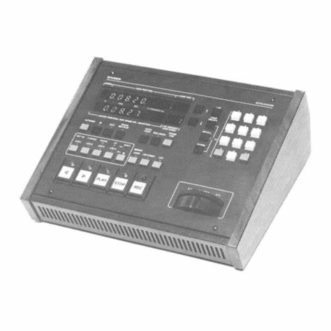
STUDER communicator A8600 controller
Product overview
The STUDER communicator A8600 controller is a core controller designed by STUDER specifically for communication and control of precision machining equipment. It undertakes key tasks such as data communication, instruction processing, and equipment coordination during the operation of precision machining equipment, and is the central brain that ensures the efficient and precise operation of the equipment. By stable communication with various components of the machine tool and external systems, the A8600 controller can achieve precise control of the machining process, ensuring that machining accuracy and production efficiency reach industry-leading levels.
Specification parameters
Communication Interface: Equipped with a variety of communication interfaces, including Ethernet interfaces, supporting high-speed and stable data transmission, making it easy to connect with factory networks and computer systems for remote monitoring and program transmission; Serial communication interfaces such as RS-232 and RS-485 can reliably communicate with various sensors and actuators, meeting the communication needs between different devices; In addition, it may also have a USB interface for quick storage and transfer of data, such as backup of processing parameters, import and export of program files, etc.
Control accuracy: Based on advanced algorithms and high-precision hardware design, the A8600 controller can achieve control accuracy at the micrometer or even nanometer level, ensuring that the moving parts of the machine tool can operate accurately according to preset instructions in precision grinding, milling and other machining processes, meeting the processing requirements of complex precision parts.
Data processing capability: Equipped with a high-performance processor and large capacity memory, it has powerful data processing capabilities and can quickly process large amounts of processing instructions, sensor data, and communication information, ensuring that the device can maintain stable and accurate control during high-speed operation.
Adaptability to working environment: It has good adaptability to working environment, can operate stably within a certain temperature and humidity range, and can resist the influence of electromagnetic interference, dust and other factors in industrial environment, ensuring reliable operation in harsh production workshop environment. Its working temperature range is generally around 0 ℃ -45 ℃, and the relative humidity range is 20% -80% (without condensation).
Core functions
Equipment communication and coordination: As the core hub of equipment communication, the A8600 controller can achieve efficient communication between various components of the machine tool, ensuring collaborative work between the spindle, feed axis, grinding wheel dresser, and other components. At the same time, it can also communicate with external systems such as computer-aided design/manufacturing (CAD/CAM) systems and production management systems, receive processing instructions, production plans, and other information, and provide feedback on equipment operation status to external systems, achieving automation and information-based management of production processes.
Process control: During the machining process, the A8600 controller can accurately control the motion trajectory, speed, feed rate, and other parameters of the machine tool according to preset machining parameters and process requirements. By monitoring sensor data in real-time, such as position sensors, force sensors, etc., the machining process can be dynamically adjusted to ensure machining accuracy and surface quality. For example, in grinding, the feed rate of the grinding wheel can be adjusted in real time according to the size changes of the workpiece to ensure the consistency of the machining dimensions.
Fault diagnosis and alarm: Equipped with an intelligent fault diagnosis system, it can monitor the operating status of equipment in real time and provide early warning and diagnosis for possible faults. Once a fault is detected, such as motor overload, sensor abnormality, communication interruption, etc., the A8600 controller will immediately issue an audible and visual alarm signal and display detailed fault information on the operation interface, helping maintenance personnel quickly locate the cause of the fault, shorten equipment downtime, and improve production efficiency.
Working principle
The A8600 controller receives processing instructions, parameter settings, and other information from external systems through a communication interface, and stores this information in internal memory. The processor inside the controller parses and processes this information, generating corresponding control signals. These control signals are transmitted through drive circuits to various actuators of the machine tool, such as servo motors, hydraulic valves, etc., to control the movement and actions of the machine tool. At the same time, sensors provide feedback on the operating status of various components of the machine tool, such as position, speed, temperature, etc., to the A8600 controller. The controller performs real-time analysis and comparison of feedback information, compares it with preset parameters, and adjusts the control signal in a timely manner if there is a deviation, so as to restore the operating state of the machine tool to the correct parameter range, thereby achieving closed-loop control and ensuring the accuracy and stability of the machining process.
FEATURES AND BENEFITS
• Four independent, high current switching regulators
• Adjustable 1.0 A/±1.5% always-on asynchronous buck
regulator with an integrated 150 mΩ MOSFET (SW1)
▫ Employs PFM to deliver 3.3 V/40 µA while drawing less
than 50 µA from VIN of 12 V
▫ Operates down to at least 3.6 VIN
• Adjustable 1.5 A/±1.5% asynchronous buck regulator with
an integrated 120 mΩ high-side MOSFET (SW2)
• Adjustable 2.0 A/±1.5% asynchronous buck regulator with
an integrated 110 mΩ MOSFET (SW3)
• Adjustable ±1.5% synchronous buck controller with
integrated gate drivers and current sensing (SW4)
• Fixed 425 kHz, interleaved PWM switching frequency
• EN/SYNC input for PWM frequency scaling
• Adjustable soft-start time for each switching regulator
• All switching regulators provide pre-bias startup with zero
reverse current
• All switching regulators have overvoltage protection
• External compensation for all switching regulators
Precautions
Installation and wiring: When installing the A8600 controller, it is necessary to strictly follow the requirements of the product manual to ensure a stable installation position and correct wiring. Pay attention to the standardization of electrical connections to avoid equipment damage or communication failures caused by wiring errors. At the same time, grounding protection should be implemented to prevent electromagnetic interference from affecting the controller.
Environmental requirements: Ensure that the working environment of the controller meets its specified temperature, humidity, dust prevention, and other requirements. Avoid installing the controller in environments with high temperature, humidity, corrosive gases, or strong electromagnetic interference to avoid affecting its performance and service life. Regularly clean the controller to prevent dust accumulation from affecting heat dissipation and normal operation.
Software management: Timely follow the official software update information released by STUDER, upgrade the software of the controller according to the correct process to obtain new features and performance optimization. Before upgrading software, it is essential to backup important programs and data to prevent data loss. At the same time, it is important to ensure the use of genuine software to avoid compatibility issues and security risks caused by the use of pirated software.
Maintenance and upkeep: Regularly inspect and maintain the A8600 controller, check whether the interface connections are secure, and whether the cooling fan is operating normally. For controllers that have malfunctioned, they should be repaired by professional maintenance personnel to avoid unauthorized disassembly and repair by non professionals, in order to prevent greater damage.