Call us 24/7uaedcs@163.com
Welcome to the official website of CNIACS Automation Technology Co., Ltd!
Call us 24/7uaedcs@163.com

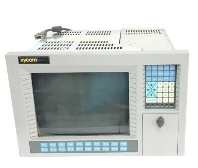
XYCOM Automatic 9987 Operating Interface PN.9987-3338-2100

The 9987 PC/AT™ Flat-panel Industrial Computer (also known as the Portrait PC) com bines a PC/AT computer with a flat-panel display to offer a powerful, compact package for the factory floor and other harsh environments. 

​The 9987 features an open architec ture to meet a wide variety of applications where both a powerful PC and a durable in dustrial enclosure are required. 

The system integrates a computer card cage, mass stor age, display, keypads, and power supply in a truly industrial form factor.

The 9987 system includes a four-slot, full-length, passive ISA backplane, a VGA flat panel display, hard and floppy disk drive facilities, and data entry/function keypads. 

The front panel is sealed to NEMA 4/4X/12 standards, and the flat-panel display is protected by an impact-resistant shield. 

The open-architecture design accepts IBM PC/AT compatible cards and keyboards.

The processor board combines the functions of a IBM PC/AT-compatible computer on a single, industrially-hardened circuit board. Refer to the Xycom CPU manual for more in formation on processor and hardware features.

The system’s modular design allows easy access to boards, switches, power supply, and disk drives. 

You can easily remove the drawer by detaching six ACCESS fasteners.

Standard Features

The 9987 offers the following standard features:

• High-performance, single-board 486 and Pentium® processors

• 5.62-inch mounting depth

• Four-slot, full-length, passive ISA backplane

• 10.4-inch 256-color CCFT TFT LCD flat-panel display (640×480)

• 32 data entry and 10 function keys

• 3.5-inch 1.44 Mbyte floppy drive

• MS-DOS®

• Slide-out computer module (to access disk, backplane, and power supply)

• 110-watt power supply

• IBM PC/AT compatibility

• Front or rear access floppy disk

• External printer port

• External COM1 and COM2 ports (RS-232)

• Front panel sealed to meet NEMA 4/4X/12 specifications when panel mounted

Optional Features

The following optional items are also available with the 9987:

• A variety of high-capacity IDE hard drives and Solid State (Flash) drives

• RADAR card with isolated RS-232C/RS-485 serial ports

• External full-stroke keyboard

• Durapoint sealed front-panel mouse

• Various sealed rack- or panel-mount keyboards

• Preloaded Windows® 95 or Windows NT operating systems

• Hazardous location configurations

Unpacking the System

When you remove the 9987 from its box, verify that you have the parts listed below. 

Save the box and inner wrapping in case you need to reship the unit.

• 9987 unit

• Documentation kit, which includes

Power cable

PKIM utility disk

Diagnostic software disk

20 hex nuts (6 spares)

9987 user manual

CPU manual

VGA utility disk

• Binder

• Business reply card

Quick Start-up

Warning

Turn off the power to the unit and unplug the power cord before making any adjust ments to the inside or outside of the computer.

Perform the following steps to prepare the system for use.

1. Attach optional keyboards/mouse.

• Connect an external keyboard to the keyboard connector behind the access door on the front panel or to the connector on the power panel.

• A serial mouse can be connected to either COM1 or COM2. When a mouse is used, the COM LED on the data entry keypad lights up.

2. Attach other optional equipment following the instructions in Chapter 3.

3. Attach the power cord from the power receptacle to a properly grounded 90-250 VAC, 50-60 Hz outlet.

4. Turn on the power to the unit. The system will boot up at the C: prompt.

5. Install application software via drive A: located behind the access door on the front panel

Quadtel BIOS

If the CPU board has a Quadtel BIOS,  press CTRL+ALT+S simultaneously after the POST RAM test has completed to access the Setup Menu. 

Make changes by following directions on the screen. 

Press F10 to save the Setup, and ESC to exit. Refer to your CPU manual for more information on the Setup Menu.

Preparing for the Tests

To test your system, you need the following equipment:

• Xycom System Test Disk (bootable 3.5-inch, DS/DD disk), Xycom part number

99290-001

• IBM PC/AT-compatible keyboard (Xycom part number 91971-001 or equivalent)

• Centronics-compatible printer cable

• Parallel printer (Centronics-style interface)

• Two serial loopback test connectors (refer to Figure 2-1 for pinouts)

• Formatted scratch disk (3.5-inch, DS/HD)

Perform the steps below before starting the system tests:

1. Place the CPU board jumpers and switches to the factory-set positions. Refer to your

CPU manual for these settings.

2. Plug the female end of the AC power cable into the side of the unit and the male end

into a properly grounded outlet.

3. Connect the serial loopback connector(s) and the printer cable to the appropriate

connectors and connect a PC/AT keyboard to a keyboard connector. Figure Chapter

2 -1 illustrates the wiring necessary for the loopback connection.

Removing the Slide-Out Module

1. Remove the six ACCESS fasteners that attach the slide-out computer module to

the 9987 back panel. (A ¼-inch nut driver is needed to remove the 8/32 size fas teners.)

2. If the unit is not panel mounted, place it face down. Hold the front part down

(located behind keypad) while pulling off the back panel to break the intercon nect connection.

3. Grasp the handles that protrude from the back panel on the left and right sides, above the I/O inserts.

4. Pull straight back. The module should slide out easily. 

9000-RAD Card

You can install the 9000-RAD card if you have an open slot. 

Before installing the card (Solid State Disk) into the 9987, jumpers and switches must be set for your par ticular configuration. 

After the 9000-RAD is properly configured, it can be installed into the 9987 card

cage as follows:

1. Unplug the 9987 from the AC wall outlet.

2. Remove the 9987 slide-out computer module (refer to the Removing the Slide

Out Module section earlier in this chapter). Set the six ACCESS fasteners aside for later use.

3. Verify jumper and switch settings. Refer to the 9000-RAD manual for the cor rect settings.

4. If present, remove the blank ORB from the slot that the 9000-RAD card will oc cupy. Save the screw.

5. Place the 9000-RAD card into the slots in the backplane. Push down on the card evenly, until it firmly seats into the card edge connectors.

FloNet Interface Board

You can also install a IPN200 FloNet interface board in your system. 

The FloNet board has two modes of operation: 

Ethernet and FloNet. In Ethernet mode, the board provides a standard Ethernet network interface with user-configurable hardware in terrupts, I/O ports, and bootable ROM BIOS address location.

In FloNet mode, the FloNet board acts as the interface between a local host running FloPro software and an Ethernet LAN connected to at least one remote host platform running TCP/IP-compatible software. 

The on-board firmware constantly polls the Ethernet network interface waiting for packets where are intended to communicate with FloPro. 

The board will also process valid TCP/IP protocol packets.

When configured for FloPro mode, the FloNet board takes up to six eight-bit I/O ports, and 32 Kbytes of memory. 

When configured as an Ethernet card, the FloNet board takes an additional 16 I/O addresses. 

It may also take up an additional 32

Kbytes of memory space if configured to use a boot ROM.

Refer to the FloNet documentation for installation instructions

PHILIPS PG 1220 SERIES WITH CPU BOARD XYCOM

PHILIPS PG 1220 SERIES WITH CPU BOARD, XYCOM XVME-491 , CNC SERVO CONTROLLER

PHILIPS PG 1220 series

(1) Product Overview

The PHILIPS PG 1220 series is an industrial equipment product launched by Philips, equipped with a CPU board, commonly used in industrial scenarios with certain requirements for device control and data processing. This series of products, leveraging Philips’ brand technology advantages, has a specific application direction in the field of industrial automation, and can work in conjunction with other industrial equipment to provide stable control and data processing support for industrial production.

(2) Specification parameters

Due to the lack of detailed information, it is difficult to clarify specific specifications. But usually such industrial equipment will have CPUs with specific clock frequencies and computing capabilities to meet the needs of industrial control instruction processing and data computation; In terms of memory, it may be equipped with moderate capacity to ensure smooth program operation; In terms of interface configuration, it is expected that there will be serial ports, Ethernet interfaces, etc. used to connect external devices for data transmission and communication.

(3) Core functions

Equipment control: By running control programs through the built-in CPU board, the connected industrial equipment is sent and controlled with operation instructions to achieve functions such as start stop and operation parameter adjustment, ensuring the orderly progress of industrial production processes.

Data interaction: By utilizing various interfaces to interact with sensors, actuators, and other control systems, data is collected from device operation and control instructions are transmitted to achieve real-time monitoring and feedback control of industrial production processes.

(4) Key advantages

Brand reliability: Relying on Philips’ strong brand influence and technological research and development capabilities, the products have high guarantees in quality control and performance stability, and can operate stably in industrial environments for a long time.

Compatibility: Considering the integration requirements of industrial equipment in the design, it has certain compatibility and can work together with various industrial standard equipment, making it convenient for users to build industrial automation systems.

XYCOM XVME -491

(1) Product Overview

XYCOM XVME-491 is a CPU board commonly used in industrial control systems as the core component for system data processing and instruction execution. It is based on XYCOM’s technological accumulation in the field of industrial automation, providing efficient and reliable computational support for industrial control, and ensuring the stable operation of control systems in complex industrial environments.

(2) Specification parameters

Processor performance: Equipped with high-performance processors, it has the ability to quickly process complex industrial control algorithms and large amounts of data, ensuring timely response and processing of industrial control instructions.

Memory configuration: It has a memory capacity suitable for industrial control requirements, supports multitasking parallel processing, and ensures smooth operation of control programs and data processing tasks.

Interface type: Equipped with rich interfaces, such as serial ports for connecting sensors, instruments, and other devices for data collection; Ethernet interface enables high-speed network communication, facilitating data exchange with other controllers and upper computers; There are other necessary interfaces to meet the connection requirements of different devices.

(3) Core functions

Data processing and computation: As a CPU board, it performs real-time processing and computation of data collected by industrial control systems, generates control instructions based on control logic, and provides decision-making basis for the operation of industrial equipment.

System coordination: In industrial control systems, coordinate the data transmission and workflow between various components to ensure the orderly operation of the entire system and achieve automated control of industrial production processes.

(4) Key advantages

High reliability: Using industrial grade components and strict manufacturing processes, after multiple reliability tests, it has excellent anti vibration, anti impact, and anti electromagnetic interference capabilities, adapting to harsh industrial environments.

Powerful Scalability: Modular design facilitates functional expansion, allowing users to add or replace functional modules according to their actual needs, such as adding communication interface modules, expanding storage capacity, etc., to meet the diverse needs of different industrial application scenarios.

CNC servo controller

(1) Product Overview

CNC servo controller is a key component of computer numerical control (CNC) system, mainly used to control the operation of servo motors, achieve precise position, speed and torque control of machining equipment such as machine tools, and play an important role in mechanical processing, manufacturing and other fields. It is one of the core equipment to ensure machining accuracy and production efficiency.

(2) Specification parameters

Control axis number: The number of controllable servo motor axes varies among different models, ranging from single axis to multi axis, to meet the needs of machining tasks of different complexity levels.

Control accuracy: With high-precision control capability, the position control accuracy can reach the micrometer or even nanometer level, and the speed control accuracy can also meet the requirements of precision machining.

Communication interface: It is usually equipped with multiple communication interfaces, such as RS-232, RS-485, Ethernet interface, and dedicated CNC communication interface, to facilitate data communication and integration with CNC systems, PLCs, and other devices.

(3) Core functions

Motor control: Based on the instructions sent by the CNC system, accurately control the speed, direction, and position of the servo motor, drive the machine tool worktable, cutting tools, and other components to move according to predetermined trajectories and speeds, and achieve precise machining of parts.

Feedback regulation: Real time reception of position and speed signals from servo motor encoders, comparison with instructions issued by CNC systems, and adjustment of motor operating status through closed-loop control algorithms to ensure machining accuracy and stability.

(4) Key advantages

High precision machining: Through precise motor control and feedback adjustment mechanisms, high-precision part machining is achieved to meet the high precision requirements of industries such as aerospace and mold manufacturing.

Efficient and stable: With fast response capability and stable control performance, it can maintain stable operation during high-speed processing, improve production efficiency, reduce processing errors and scrap rates.

XYCOM CPU XVME-674 AT Processor Module - Sichuan Seeiyo Technology CO.,Ltd

XYCOM 3512KPT 139649-002A DHL

Product Overview

XYCOM 3512KPT (product number 139649-002A) is an industrial product with specific functions and application scenarios, which may belong to the XYCOM industrial computer or control module series products. This product plays an important role in industrial automation, data processing, and other fields, providing strong support for industrial production and equipment control with its stable performance and reliable quality. Shipping through DHL means that its global circulation is more convenient, making it easier for users to purchase and obtain products.

Brand background

XYCOM, as an important brand under PRO-FACE, has a profound technical accumulation and good market reputation in the field of industrial automation. PRO-FACE has always been committed to providing high-quality human-machine interfaces, industrial computers, and control system solutions for industrial users. The XYCOM series products inherit the brand’s pursuit of technological innovation and product reliability, and are widely used in multiple industries such as energy, manufacturing, and transportation, and are highly trusted by industrial customers.

​Specification parameters

Processor and Performance: Equipped with high-performance processors to meet the complex data processing and control task requirements in industrial environments. For example, using Intel series processors, it has high computing speed and multitasking capability, and can quickly respond to the instructions and data acquisition needs of industrial equipment.

Memory and Storage: Having a certain capacity of memory ensures smooth program operation and supports stable operation of industrial control software and data processing programs. At the same time, equipped with suitable storage devices such as hard drives or solid-state drives, for storing system programs, user data, and various parameters and records in industrial production processes.

Interface configuration: It usually has rich interfaces, including but not limited to Ethernet interfaces, used to achieve network connection and data transmission of devices, facilitating communication with other devices in industrial networks; Serial ports (such as RS-232, RS-485, etc.) can connect various industrial sensors, instruments, and actuators to achieve data acquisition and device control; USB interface facilitates the connection of external devices such as storage devices and printers, meeting the diverse needs of industrial sites.

Working environment parameters: It has good industrial grade protection performance and can adapt to harsh working environments. For example, it has certain anti vibration and anti impact capabilities, and can operate stably in environments with mechanical vibrations such as industrial production workshops; Capable of dust and water resistance, meeting the corresponding industrial protection level standards, and can work normally in environments with high dust or humidity; At the same time, it can adapt to a wide temperature range, ensuring reliable operation in high or low temperature environments.

Core functions

Industrial automation control: XYCOM 3512KPT is likely to serve as the core control unit of industrial automation systems, connecting various equipment on the production line such as robots, CNC machines, conveyors, etc. By running pre written control programs, precise control and coordination of equipment are achieved to ensure efficient and stable industrial production processes. For example, in the automobile manufacturing production line, controlling robots to complete operations such as welding and assembly of components, accurately adjusting the processing parameters of CNC machine tools, and ensuring product quality and production efficiency.

Data collection and processing: Utilizing rich interfaces to collect real-time data from various sensors on industrial sites, such as temperature, pressure, flow rate, location, and other information. Real time processing and analysis of collected data, extraction of key features and parameters, providing accurate data support for optimization, fault diagnosis, and quality control of industrial production processes. At the same time, the processed data can be stored or transmitted to other systems to achieve data sharing and further utilization, helping enterprises achieve intelligent production management.

Communication and Networking: Supports multiple industrial communication protocols such as Modbus, Profibus, Ethernet/IP, etc., enabling seamless communication with devices and control systems from different manufacturers. Connect to the industrial network through network interfaces to achieve data exchange and remote control with the upper computer, other controller modules, and remote monitoring center. Users can monitor the real-time operation status of industrial production equipment through the remote monitoring center, perform remote operations and management, and improve the efficiency and convenience of production management.

Working principle

In industrial control systems, XYCOM 3512KPT first receives input signals from sensors through various interfaces. After signal conditioning and conversion, these signals are transmitted to the processor for processing. The processor analyzes and performs operations on input data based on pre written control programs and algorithms, generating corresponding control instructions. Control instructions are then transmitted to actuators such as motors, valves, etc. through digital or analog output interfaces to achieve control of industrial equipment. At the same time, the product maintains data interaction with other devices and systems through communication interfaces, obtains real-time system status information, and feeds back its own operating status to the upper computer or monitoring system to achieve comprehensive monitoring and management of industrial production processes.

Key advantages

High reliability: Adopting industrial grade design and manufacturing standards, using high-quality components, and undergoing rigorous testing and quality verification, it has excellent anti-interference ability and stability. Capable of long-term stable operation in harsh industrial environments, effectively reducing equipment failure rates, minimizing production interruptions caused by equipment failures, ensuring the continuity of industrial production, and lowering maintenance costs and production risks for enterprises.

Powerful compatibility: Rich interfaces and extensive communication protocol support enable it to be compatible with the vast majority of industrial equipment and control systems on the market. Both the construction of new systems and the upgrading and transformation of existing industrial control systems can be easily achieved, greatly improving the convenience and flexibility of system integration, providing convenient conditions for industrial automation transformation of enterprises, and reducing the difficulty of system development and integration.

Efficient performance: High performance hardware configuration and optimized software algorithms enable it to quickly handle complex industrial control tasks and large amounts of data. In the case of multitasking and large data transmission, it can still maintain a stable and efficient operating state, ensure the real-time and accuracy of industrial production processes, improve the efficiency and quality of industrial production, and meet the needs of modern industrial production for efficient and precise control.

Precautions

Installation and debugging: When installing XYCOM 3512KPT, it is necessary to strictly follow the requirements of the product manual to ensure a stable installation position and avoid equipment damage caused by vibration or collision. During the wiring and debugging process, it is important to carefully check the interface type and pin definitions, correctly connect power lines, signal lines, and communication lines to prevent equipment damage or system failures caused by wiring errors. At the same time, sufficient preparation work should be done before debugging, and important data should be backed up to ensure the safety and smoothness of the debugging process.

Work environment requirements: To ensure the normal operation and service life of the equipment, it should be installed in a working environment that meets the requirements. Keep the installation environment well ventilated, dry, free of corrosive gases and strong electromagnetic interference. Avoid prolonged exposure of equipment to high temperatures, high humidity, or excessive dust. Regularly clean and maintain the equipment, remove surface dust and debris, and ensure good heat dissipation. If the working environment cannot meet the requirements, corresponding protective measures should be taken, such as using protective cabinets, installing heat dissipation devices, etc.

Software and Data Management: When programming, configuring, and upgrading software, it is necessary to use official development tools and software versions, and follow the correct operating procedures. Before downloading programs or updating software, it is essential to perform data backup to prevent data loss or system crashes caused by operational errors or software failures. At the same time, attention should be paid to software compatibility to ensure that newly installed software can work properly with device hardware and other related devices. Regularly organize and backup data in devices, establish a comprehensive data management mechanism, and ensure the security and integrity of data.

Similar model supplement

XYCOM 3513KPT: Belonging to the same series as XYCOM 3512KPT, it shares similarities in overall architecture and functionality, but may have undergone upgrades and improvements in certain aspects. For example, there may be an improvement in processor performance, with higher computing speed and processing capabilities, which can better meet industrial application scenarios that require high real-time performance and data processing; In terms of interface configuration, new interfaces may have been added or the transmission rate of interfaces may have been improved, further enhancing the connection capability and communication efficiency of devices, making it suitable for more complex industrial automation systems.

XYCOM 3511KPT: As a simplified version of 3512KPT, it is relatively basic in hardware configuration and functionality. It may be suitable for industrial application scenarios that are cost sensitive and have relatively simple control tasks, such as small automated production lines or simple equipment monitoring systems. Although the performance and functionality have been simplified, XYCOM products still maintain their consistent reliability and stability, meeting the basic control needs of users. It is an affordable industrial control solution.

XYCOM 3512 KPM

XYCOM XVME-202 Controller Module Board

Overview

The XVME-202 PAMUX Controller Module is a single-high VMEbus-compatible interface to the

PAMUX 4, 5, and 6 remote I/O products available from OPTO 22.

The PAMUX is a high-speed distributed I/O system which provides for connection to a VMEbus system via a Xycom Automation XVME-202 module and a 50 conductor flat ribbon cable. 

The PAMUX system provides a family of Digital and Analog Intelligent Brain Boards that may be daisy-chained to provide a total of 500 I/O points. 

The PAMUX Brain Boards may be placed at distances up to 500 feet from the VMEbus master controller.

The XVME-202 board, when combined with the PAMUX equipment form OPTO 22, provides a high

performance remote I/O subsystem ideally suited for the VME environment

Features

• Directly compatible with the OPTO 22 line of

PAMUX 4, 5, and 6 I/O systems

• 16 PAMUX units can be addressed from one

XVME-202 module, providing up to 512 indi

vidual control points

• Cable length between the XVME-202 and the

PAMUX units can be up to 500 feet

Applications

• Robotics

• Numerical Control

• Conveyor Control

• Fault Detection Machinery

Product Overview

XYCOM XVME – 202 Controller Module Board  It is a high-performance controller module board designed specifically for the field of industrial automation control. As an important member of the XYCOM product series, it undertakes critical control and data processing tasks in industrial control systems with advanced technology and reliable performance. This module board can adapt to various industrial application scenarios, providing a solid hardware foundation for the efficient operation and automation control of industrial equipment.

Specification parameters

Processor performance: Equipped with high-performance processors, capable of quickly processing complex instructions and large amounts of data in industrial control processes. The powerful computing capability ensures timely response to tasks such as sensor data acquisition, equipment status monitoring, and control command output in real-time control scenarios, providing strong support for the stable operation of industrial automation systems.

Memory and storage: With an appropriate amount of memory space, it can meet the needs of program operation and data caching, ensuring the smooth execution of control programs. At the same time, it has a certain storage capacity for storing important information such as system programs, control algorithms, and historical data of device operation, which facilitates users’ data analysis and system debugging.

Interface configuration: It has a rich variety of interfaces, including but not limited to serial ports (RS-232, RS-485, etc.), Ethernet interfaces, digital input/output interfaces, and analog input/output interfaces. Serial port can be used to connect various industrial instruments and sensors to achieve data acquisition; The Ethernet interface supports high-speed network communication, facilitating data exchange and remote monitoring between the module board and other devices or control systems; Digital and analog input/output interfaces can directly connect actuators and control objects, achieving precise control of industrial equipment.

Working voltage

​Supports specific range of working voltage input, such as [specific voltage range], to adapt to the power supply conditions of different industrial sites. The stable voltage adaptability ensures the reliable operation of the module board in complex power environments, reducing the risk of equipment failure caused by voltage fluctuations.

Working temperature range: capable of stable operation within a wide temperature range, such as [- [X] ℃ – [X] ℃]. Whether in high-temperature industrial production workshops or cold outdoor work environments, it can function normally and demonstrate excellent environmental adaptability.

Key advantages

High reliability: Using industrial grade components and rigorous manufacturing processes, after rigorous testing and quality verification, it has excellent resistance to vibration, impact, dust and water, and can operate stably in harsh industrial environments, effectively reducing equipment failure rates, minimizing production interruptions caused by equipment failures, and ensuring the continuity of industrial production.

Powerful compatibility: Rich interfaces and extensive communication protocol support enable it to be compatible with the vast majority of industrial equipment and control systems on the market. Both the construction of new systems and the upgrading and transformation of existing industrial control systems can be easily achieved, greatly improving the convenience and flexibility of system integration and reducing users’ system development and maintenance costs.

Flexible Scalability: The modular design concept enables XYCOM XVME-202 Controller Module Board to have good scalability. Users can easily add or replace functional modules according to their actual application needs, such as adding communication interface modules, expanding storage capacity, etc., to meet the constantly changing industrial control requirements, extend the service life and application value of equipment.

Efficient performance: The high-performance processor and optimized software architecture enable it to quickly handle complex industrial control tasks, achieving real-time control and precise adjustment of industrial equipment. In the case of multitasking and large data transmission, it can still maintain a stable and efficient operating state, improving the efficiency and quality of industrial production.

Precautions

Installation and wiring: When installing the module board, it is necessary to strictly follow the requirements of the product manual to ensure a stable installation position and avoid damage to the module board due to vibration or collision. During the wiring process, it is necessary to carefully check the interface type and pin definitions, correctly connect the power line, signal line, and communication line, and prevent equipment damage or system failure caused by wiring errors. At the same time, attention should be paid to grounding measures to reduce the impact of electromagnetic interference on the module board.

Working environment: To ensure the normal operation and service life of the module board, it should be installed in a well ventilated, dry, non corrosive gas and strong electromagnetic interference free environment. Avoid exposing the module board to high temperature, high humidity, or excessive dust for a long time. Regularly clean and maintain the equipment, remove surface dust and debris, and ensure good heat dissipation of the equipment.

Software operation: When programming, configuring, and upgrading software, it is necessary to use official development tools and software versions, and follow the correct operating procedures. Before downloading programs or updating software, it is essential to perform data backup to prevent data loss or system crashes caused by operational errors or software failures. At the same time, attention should be paid to software compatibility to ensure that newly installed software can work properly with module board hardware and other related devices.

Power management: Use power adapters that meet the specifications of the module board to ensure stable power supply voltage and sufficient output power. To avoid using module boards in situations where the power supply is unstable or the voltage fluctuates greatly, it is recommended to equip them with uninterruptible power supplies (UPS) to cope with sudden power outages and ensure that the module board has sufficient time for data storage and normal shutdown to prevent data loss and equipment damage.

Xycom Automation Pro-face Model 4115T Pentium

Xycom Automation industrial computers (IPCs) are designed to provide processing power and versatility.

The 4115T IPC offers a powerful pro cessor with a wide range of features and an expansion slot.

The 4115T also meets the rigorous requirements of the plant floor with a high resolution LCD flat panel display in a rugged housing ideal for today’s manufacturing environment.

Higher Performance

The 2.0 GHz Intel Pentium 4 CPU with 512 KB cache and 533 MHz system bus drives the fastest and most demanding applications.

Pre-loaded Operating Systems All 4115T systems come standard with either Windows 2000 or Windows XP pre-loaded.

The unit is also available with no operating system loaded.

Sharp, Easy-to-Read Displays A bright 15″ TFT screen can display complex operations with clarity.

Full Complement of I/O Ports

The 4115T comes standard with an extensive array of I/O ports (see right), including two high-speed RS-232 ports, one configurable RS-232/422/485 port, one parallel port, two USB ports, PS/2 mouse & keyboard ports, one 10/100 Mbps Ethernet port, one VGA port, and audio I/O (input, output, and mic).

The VGA port can be used to connect a VGA monitor.

The built-in display and an external monitor can be used simulta neously (both showing the same image).

Temperature Specification

The 4115T has a faster, more powerful CPU which generates more heat than units with lesser performing

CPUs. Using Xycom’s expertise and experience, we have added a secondary system fan, more LCD venting, and a direct CPU vent channel to dissipate the extra heat.

When installing a higher performing CPU equipped unit into an enclosure, extra care should be exercised to ensure that the ambient air around the unit (inside your enclosure, not outside the enclosure) does not exceed 50° C. Exceeding 50° C may cause premature degeneration of the unit.

Consult your enclosure manufacturer for proper sizing and/or cooling options.

The product specifications and ratings section of this datasheet contains information your enclosure manufacturer will require.

PRODUCT CONFIGURATION

Model:4115T

Display:15″ LCD color display, 1024 x 768 (XGA)

Operator Input:Analog resistive touchscreen

Processor:Intel® Pentium® 4, 2.0 GHz

Preloaded OS 1:None, Windows® 2000, or Windows® XP

Expansion:One half-length PCI

Product Overview

Xycom Automation Pro – face Model 4115T is a high-performance computer designed specifically for the industrial automation field. It is equipped with a Pentium 4 2GHz processor and 640KB RAM, which can stably and efficiently run various industrial control programs and data processing tasks in industrial production processes. As a product under the PRO-FACE brand, it inherits the brand’s technological advantages and quality assurance in the field of industrial computers, aiming to provide reliable automation solutions for industrial users.

Specification parameters

Processor: Equipped with a Pentium 4 2GHz processor, it has strong computing power and can quickly process various instructions and data in industrial control processes, providing guarantees for the real-time performance of industrial automation systems. When faced with tasks such as real-time control instruction parsing and complex process parameter calculation of production line equipment, it can efficiently complete processing work.

Memory: Equipped with 640KB RAM, although the capacity may seem small in the current situation where computer memory is generally large, in industrial application scenarios, combined with optimized design of its operating system and control program, it can meet basic program running and data caching requirements. It can ensure the stable operation of industrial control software and ensure the smoothness of data processing and transmission.

Storage: Although specific storage information is not mentioned, as industrial computers, they are usually equipped with hard drives or other storage devices to store programs, configuration files, and historical data in the industrial production process, in order to meet the needs of data storage and management in industrial production.

Interfaces: Usually equipped with rich interfaces, such as Ethernet interfaces, serial ports (RS-232, RS-485, etc.), USB interfaces, etc. Ethernet interface can achieve connection with industrial networks, facilitating remote transmission of data and remote monitoring of devices; Serial ports are suitable for connecting various industrial sensors, instruments, and other devices to achieve data collection; The USB interface is convenient for external storage devices, printers, etc., meeting the diverse device connection needs of industrial sites.

Display: It has good display output capability and can support industrial grade displays, clearly displaying various monitoring screens, data charts and other information in the industrial production process, making it convenient for operators to intuitively understand the production status.

Core functions

Industrial automation control: As the core equipment of industrial automation systems, it can connect various devices on the production line, such as robots, CNC machines, conveyors, etc. By running pre written control programs, precise control of equipment is achieved, coordinating the workflow between various devices to ensure efficient and stable operation of the production line. For example, in the automotive manufacturing production line, the movements of robots can be precisely controlled to complete operations such as welding and assembly of automotive components.

Data collection and processing: Utilizing rich interfaces to collect real-time operational data of various equipment in industrial sites, such as temperature, pressure, speed, etc. Perform preliminary processing and analysis on the collected data, extract key information, and store or transmit it to other systems for further processing. Provide data support for the optimization, fault diagnosis, and quality control of industrial production processes.

Communication and Networking: Supports multiple industrial communication protocols such as Modbus, Profibus, etc., enabling seamless communication with devices from different manufacturers and achieving interconnectivity in industrial networks. Access the enterprise internal network or industrial Internet through the Ethernet interface to realize data sharing and remote monitoring. Managers can understand the situation of the production site at any time and anywhere, and conduct remote operation and management.

NEW XYCOM 9450-27B1319010000 OPERATOR PANEL 945027B1319010000 - SB ...

PRO face Xycom 1341 egemin PM-070016 computer

The PRO face Xycom 1341 egemin PM – 070016 computer, with the part number P/N 701301 – 01, is a specialized industrial – grade computing device. It belongs to the Xycom series by PRO – FACE, a brand renowned for its contributions to industrial automation. This model is designed to meet the specific demands of industrial environments, offering reliable performance and compatibility with various industrial systems.

Key Features

Fanless Design: As a fanless embedded controller, it is highly suitable for dusty or harsh industrial settings. The absence of fans reduces the risk of dust ingress, which could otherwise lead to component overheating and system failures. This design also minimizes noise, making it ideal for environments where quiet operation is preferred.

Configuration Options: It comes with options such as 1300 – 1GB – 4GB of memory, allowing users to choose the configuration that best suits their application requirements. Additionally, it can be equipped with an XP operating system along with a 1G bit PCI e – net card, enhancing its networking capabilities for seamless integration into industrial networks.

Reliable Performance: Having been sourced from factory surplus used stock in some cases, this computer has been fully tested to ensure it is in great working condition. Sellers often guarantee its functionality, providing a 100% assurance that it will operate as expected. In fact, some offer a 30 – day money – back warranty in case the product does not perform properly, instilling confidence in buyers.

Physical Specifications

Size and Weight: With estimated shipping dimensions of 9.5″ x 9.5″ x 4.0″ (24.1 cm x 24.1 cm x 10.2 cm) and a weight of 11 lbs 8.0 oz (5.2 kg), it has a compact form factor that can be easily installed in various industrial setups. However, its weight is substantial enough to suggest a sturdy build, which is typical for industrial – grade equipment designed to withstand vibrations and shocks.

Origin: This computer is manufactured in the United States, adhering to high – quality manufacturing standards. The country of origin often implies a certain level of quality control and reliability, which is crucial for industrial applications where downtime can be costly.

Applications

Industrial Automation: It can be used in industrial automation systems to control and monitor various processes. Its networking capabilities enable it to communicate with other devices in the automation setup, such as sensors, actuators, and other controllers. For example, in a manufacturing plant, it could be used to manage the operation of conveyor belts, robotic arms, or other automated machinery.

Data Acquisition and Monitoring: With its ability to handle different memory configurations and network connectivity, it is well – suited for data acquisition and monitoring tasks. It can collect data from multiple sensors in an industrial environment, such as temperature, pressure, or flow sensors, and transmit this data to a central control system for analysis. This makes it valuable in industries like oil and gas, where continuous monitoring of process variables is essential for safe and efficient operation.

PFXSP5B10 | Pro-face Xycom Box Module Proface SP5000 Modular Displays

Xycom 2050T interface workstation 1.12/. 70AMP 110/240Vac 12

Product Overview

Xycom 2050T interface workstation is a powerful interface workstation designed to provide efficient and stable connectivity and data exchange capabilities for industrial automation and control systems. It plays a key role in industrial production environments, enabling data transmission and communication between different devices and systems, ensuring the collaborative operation of the entire industrial system. The model suffix and accompanying parameters “1.12/. 70AMP 110/240Vac 12” further clarify some characteristics of the device, such as possible version information, electrical specifications, etc., which enable it to adapt to diverse industrial scene requirements.

Brand background

Continuing the profound foundation of PRO-FACE in the field of industrial automation, the Xycom 2050T interface workstation inherits the brand’s consistent pursuit of quality and innovation. With years of technological accumulation in industrial computers and human-computer interfaces, PRO-FACE has endowed Xycom 2050T with reliable performance and powerful functions, making it highly competitive in the industrial market and a trusted choice for many industrial enterprises.

Specification parameters

Electrical parameters: According to “70AMP 110/240Vac”, the current carrying capacity of this workstation can reach 70 amperes, with an input voltage range of 110-240Vac AC. This wide voltage input design enables it to adapt to the application needs of different regions and power environments, and has good power compatibility.

Interface configuration: As an interface workstation, its core lies in a rich and diverse range of interface types. Although the specific types of interfaces are not yet clear, they usually include Ethernet interfaces, serial ports (such as RS-232, RS-422, RS-485, etc.), USB interfaces, etc., to meet the connection requirements with various industrial equipment such as sensors, controllers, actuators, etc., and achieve efficient data transmission and communication.

Performance parameters: Equipped with a powerful processor and sufficient memory, it can quickly process large amounts of industrial data and complex communication protocols, ensuring stable and efficient operation even in multi device connections and large data transmission. At the same time, high-capacity storage devices can be used to store system programs, device configuration information, and important industrial data records.

Core functions

Data Communication and Protocol Conversion: Supports multiple industrial communication protocols such as Modbus, Profibus, Ethernet/IP, etc., enabling data communication and protocol conversion between devices with different protocols. In complex industrial systems, devices from different manufacturers may use different communication protocols. The Xycom 2050T interface workstation can act as a “translator” to enable these devices to “talk” to each other, achieving smooth data exchange and sharing.

Equipment connection and centralized management: Through rich interfaces, a large number of industrial equipment can be connected, and various devices scattered in the industrial field can be centrally connected to workstations. Users can centrally manage, configure, and monitor connected devices through workstations, obtain real-time operational status information of devices, and improve the management efficiency and operational convenience of industrial systems.

Data processing and analysis: Possess certain data processing capabilities, able to perform real-time analysis, processing, and storage of collected industrial data. For example, conducting statistical analysis on equipment operation data, predicting equipment failures, conducting maintenance in advance, reducing equipment downtime, and ensuring the continuity and stability of industrial production.

Working principle

The Xycom 2050T interface workstation operates based on computer architecture and communication technology principles. After connecting to industrial equipment, receive data signals sent by the equipment through the corresponding interface, and parse the data according to the preset communication protocol. The parsed data is transmitted to the processor of the workstation for processing, and the processor performs analysis, calculation, and other operations on the data according to program logic. After processing, the data can be stored according to requirements, or converted according to other protocols and sent to other devices or systems through corresponding interfaces. At the same time, the workstation provides users with an operation interface for device management and data monitoring through human-computer interaction interfaces (such as display screens, operation panels, etc.). Users can send instructions through the interface to control the operation of the workstation and equipment.

Key advantages

High compatibility and flexibility: With powerful protocol support and rich interface configurations, it can be compatible with the vast majority of industrial equipment on the market, whether it is upgrading and renovating old equipment or integrating new equipment, it can easily cope. Meanwhile, users can flexibly configure interfaces and communication protocols according to their actual needs to meet diverse industrial application scenarios.

Reliable stability: Adopting industrial grade hardware design and manufacturing processes, it has good anti vibration, anti impact, dustproof and waterproof capabilities, and can operate stably in harsh industrial environments. At the same time, through rigorous testing and verification, it ensures reliable performance even under long-term continuous operation, reducing the risk of equipment failure.

Efficient data processing capability: High performance hardware configuration and optimized data processing algorithms enable it to quickly process large amounts of industrial data, ensuring real-time and accurate data communication. In industrial automation production, timely and accurate data processing is crucial for controlling and optimizing the production process, and the Xycom 2050T interface workstation can meet this requirement.

​Precautions

Installation and electrical connection: During installation, it is necessary to strictly follow the requirements of the product manual to ensure a stable installation position and good ventilation. When making electrical connections, it is necessary to confirm that the input voltage matches the equipment specifications, use appropriate power cords, and ensure good grounding to prevent electrical faults and safety accidents.

Interface usage and device connection: Before connecting the device, it is necessary to clarify the interface type, communication protocol, and electrical parameters of the device to ensure compatibility with the workstation interface. When connecting, avoid excessive pulling or bending of the interface cable to prevent damage to the interface. At the same time, pay attention to the plugging and unplugging sequence of interfaces, and avoid randomly plugging and unplugging interfaces during device operation to avoid data loss or device damage.

Software configuration and maintenance: When configuring software, it is necessary to use the official configuration tools and software provided, and follow the correct operating procedures for setting up. Regularly update the system software and drivers of the workstation to fix vulnerabilities and improve performance. At the same time, do a good job in data backup to prevent production interruptions caused by software failures or data loss.

Similar model supplement

Xycom 2060T: As a product in the same series, Xycom 2060T has similarities in functionality and architecture with 2050T, but may have upgrades in performance and interface configuration. For example, it may be equipped with more powerful processors that provide higher computing power to meet more complex data processing requirements. In terms of interfaces, new types of interfaces may have been added or the transmission rate of interfaces may have been improved, further enhancing the device’s connectivity and data transmission efficiency.

Xycom 1950T: Compared to 2050T, Xycom 1950T may be slightly inferior in performance and functionality, but still has advantages in some specific industrial scenarios. For example, in small industrial systems that are cost sensitive and have relatively low data processing requirements, the 1950T, with its relatively economical price and stable basic performance, can meet basic equipment connection and data communication needs.

NEW XYCOM 9450-27B1319010000 OPERATOR PANEL 945027B1319010000 - SB ...

XYCOM 1546 PROFACE Industrial Computer

Product Overview

XYCOM 1546 PROFACE Industrial Computer with RS View 32 Batch Q302 is a high-performance computer device designed specifically for harsh industrial environments. It combines powerful computing power, rich interface configuration, and excellent stability, aiming to meet the needs of various complex industrial application scenarios such as industrial automation, process control, data acquisition and monitoring. This computer has a compact design, making it easy to install and deploy in environments with limited space such as factory workshops and control cabinets. At the same time, its sturdy and durable casing can effectively resist the effects of harsh factors such as vibration, impact, dust, and moisture, ensuring long-term reliable operation in various industrial sites.

Specification parameters

Processor: Supports Intel ®  socket 478 Celeron ®  M or Pentium ®  M option, up to 2.0GHz, 400MHz or 533MHz front-end bus (depending on processor type), can efficiently handle various complex industrial control algorithms and data computation tasks.

Memory: Equipped with two 240 pin DDR2 DIMM slots, supporting multiple capacity options of 256MB, 512MB, 1GB, and 2GB. The system DRAM can reach 4M and can be expanded up to 32M, ensuring smooth program operation and efficient performance even during multitasking.

Storage: Provides CompactFlash ™ Option, supports up to 4GB, can be used to store important industrial data, program files, and system configuration information.

Interface: It has four serial COM ports, with three external ports configured as RS-232 and one configurable as RS-232, RS-422, or RS-485, making it convenient for serial communication with various industrial equipment; Simultaneously equipped with other common interfaces such as Ethernet interface, USB interface, etc., to meet the connection requirements of different devices.

Display: AGP video controller with 4M system memory, capable of providing clear and stable image display effects, meeting the display needs of industrial monitoring screens.

Power supply: The input voltage range is 100-240VAC, frequency is 50-60Hz, current is 1A, suitable for power supply environments in different regions, and has good power supply stability and anti-interference ability.

Environmental parameters: The maximum ambient temperature can reach 50 ° C, temperature code T6, in compliance with Class I, Division 2, Groups A, B, C, and D standards, and can operate stably in harsh environments such as high temperatures and potentially explosive gases.

Excessive Heat

The units withstand temperatures from 0º to 50ºC, and are fan-cooled.  

To keep the temperature in range, the cooling air at the base of the system must not exceed 50°C. 

Allocate proper spacing between internal components installed in the enclosure.  

Electrical Noise

Electrical noise is seldom responsible for damaging components, unless extremely high energy or high voltage levels are present. 

However, noise can cause temporary malfunctions, which can result in hazardous machine operation in certain applications. 

Noise may be present only at certain times, may appear at widespread intervals, or in some cases may exist continuously.

Noise commonly enters through input, output, and power supply lines and may also be coupled through the capacitance between these lines and noise signal

carrier lines. 

This usually results from the presence of high voltage or long, close  spaced conductors. 

When control lines are closely spaced with lines carrying large currents, the coupling of magnetic fields can also occur. 

Use shielded cables to help minimize noise. 

Potential noise generators include switching components, relays, solenoids, motors, and motor starters.

Refer to the relevant Federal, State/Provincial, and local electric codes, which provide data such as the size and types of conductors, color codes and connections necessary for safe grounding of electrical components. 

It is recommended that the high voltage and low voltage cabling be separated and dressed apart. In particular,the AC cables and switch wiring should not be in the same conduit with all communication cables.

Line Voltage Variation  

The unit’s power supply is built to operate with an input voltage range of 100 240VAC, while still allowing the system to function within its operating margin.

As long as the incoming voltage is adequate, the power supply provides all the logic voltages necessary to support the processor, memory, and I/O.

In cases in which the installation is subject to unusual AC line variations, use a constant voltage transformer to prevent the system from shutting down too often.

However, a first step toward the solution of the line variations is to correct any possible feed problem in the distribution system. If this correction does not solve

the problem, use a constant voltage transformer.

The constant voltage transformer stabilizes the input voltage to the 1546 and 1547 units by compensating for voltage changes at the primary in order to maintain a steady voltage at the secondary. 

When using a constant voltage transformer, check that the power rating is sufficient to supply the unit.

AC Power Cable

A power cable must be created to supply power to the unit. 

The following materials are needed:  

A three-position power connector (supplied)

A braid/foil shielded power cable, terminated at power source end, with three 18 (1.0 mm), 16 (1.3 mm), or 14 (1.6 mm) AWG solid or stranded copper

wires, rated 80ºC or better

Perform the following steps to construct and attach the cable:

Cut wire cable to the desired length.

Strip 0.25-inch (6 mm) of insulation from the end of the conductor wire. No bare wire should be exposed when the cable is connected to the workstation.

Tin the wire ends with solder if using stranded wire. 

This will keep the wire from fraying.

Insert the three wire ends of the power cable into the hole of the connector plug.

Bend the Protective Earth ground (PE) wire, the neutral (N) wire, and the line(L) wire around the corresponding screw. Be sure that no bare wires are exposed.

Tighten the three screws above the wires to hold them firmly in place..

Use the screw provided to secure and strain-relief the power cable inside the connector. 

Plug the power cable into the power supply located on the side of the unit.  

Install the plug retainer bracket over the plug (mandatory for hazardous location installations).

Once the power cable and other optional interface cables are installed, installation is complete.

DRAM and Additional DRAM Dual Inline Memory Modules DIMMs)

You can order the 1546/1547 system CPU factory-configured for many configurations of DRAM. 

The system has two 240-pin DDR2 DIMMs that support 512, 1GB and 2GB options. 

The maximum amount supported is 2GB. 

You can reconfigure the DDR2 capacity by changing the DDR2 DIMMs on your board.

​PC/AT® and PCI Boards  

Check the memory and I/O configuration of the board you want to install so that it does not conflict with the CPU and I/O memory maps in your AIM4

documentation.

Remove the lid.

Remove the ORB screw from the desired slot.

Slide the PC/AT expansion board into the corresponding rail.

Push the board into the backplane connectors.

Secure the board by installing the screw through the hole in the board’s metal

ORB and into the top of the track.  

Replace the lid.

Hazardous Locations Installation

Xycom Automation designed the 1546 and 1547 Node Box Industrial PCs to meet the requirements of Class I, Division 2 Hazardous Locations applications. Division 2 locations are those locations that are normally non-hazardous, but could become hazardous due to accidents that may expose the area to flammable vapors, gases or combustible dusts.

These systems have been designed as non-incendiary devices. 

They are not intrinsically safe and should never be operated within a Division 1 (normally hazardous) location when installed as described here. 

Nor should any peripheral interface device attached to these systems be located within Division 1 locations unless approved and/or certified diode barriers are placed in series with each individual signal and DC power line. 

Any such installations are beyond the bounds of Xycom design intent. 

Xycom Automation accepts no responsibility for installations of this equipment or any devices attached to this equipment in Division 1 locations. 

REFURBISHED XYCOM 3612KPM PROFACE OPERATOR INTERFACE 1000-256-CDF-2K ...

PRO-FACE XYCOM 1546 Heavy Industrial PC

Product Overview

The 1546 and 1547 Node Box Industrial PCs offer a powerful, compact package for the factory floor and other harsh environments.  

These node box industrial PCs feature an open architecture to meet a wide variety of applications that require both a powerful PC and a durable industrial enclosure. 

The systems integrate a computer card cage, mass storage, and power supply in a truly industrial form.

The processor board combines all the functions of a complete PC/AT® compatible computer on a single industrially hardened circuit board.  

Standard Features  

The 1546 and 1547 units come standard with the following features:

AIM4 board

Wall or shelf mountable

Flash BIOS

SATA HD controller for up to 2 drives

Removable 40 GB SATA hard drive(s), rear access

AGP Video Controller, 4M of system DRAM, up to 32M

PCI local bus IDE controller (for CD/DVD and CF options)

Two 240 pin DDR2 DIMM sockets that support 256MB, 512MB, 1GB and 2GB options

Intel® Socket 478 Celeron® M or Pentium® M options up to 2.0GHz 400MHz or 533MHz front side bus depending on the processor type 1546 – Four AT bus expansion slots  

One PCI (8.0” max)

One PCI (9.0” max)

One ISA (9.0” max)

One PCI or ISA slot (9.0” max)

1547 – Four AT bus expansion slots  

One ½ length PCI

One full length PCI

One full length ISA

One full length PCI or ISA slot

IBM® PS/2® keyboard port and mouse port

Four serial COM ports, with three external ports configured as RS-232 and one

configurable as either RS-232 or RS-422 or RS-485. The fourth port is an

internal header only and defaulted as disabled.

Parallel port  

VGA port

Four USB 2.0 ports

Legacy USB keyboard and mouse support

Legacy USB floppy, USB CDROM, and USB mass storage support

Two onboard Ethernet ports, one is a 10/100 BASE T and the other is 10/100/1000 BASE T

Microsoft Windows XP® operating system

Internal rear access Compact Flash (CF) interface 120/240 VAC 50/60Hz Auto switching power supply

UL Listed for use in Class I and Class II, Division 2 hazardous locations, Groups

A, B, C, D, F, and G

Optional Features

Following are optional available features of the 1546 and 1547:

Higher capacity SATA hard drives and solid state drives  

Various CD/DVD drive options

Internal rear access floppy

Various processor speeds

Preinstalled Windows® 2000, or Windows XP® Professional

External 9000-USBF, USB floppy (requires Windows 2000, or XP)

CompactFlash™ options up to 4GB

2.5” Dual hard drives

2.5” RAID array support

24VDC power supply (on 1547 units only)

The figures and tables on the next several pages illustrate the internal and external components on the front and back panels of the unit to help you locate the features of the 1546 and 1547 Node Boxes.

Unpacking the System

When you remove the system from its shipping container, verify that you have the parts listed below. 

Save the box and inner wrapping in the event you need to reship the unit.

1546 or 1547 unit

Documentation kit, which includes:

Power connector

Cable clamp and screw (for strain relief of power cord)

Documentation and Support Library CD-ROM

Operating System Recovery Media or retail operating system (CD-ROM)

Mounting hardware

The rugged design of the 1546 and 1547 Node Boxes allows it to be installed in most industrial environments. 

The system is generally placed in a NEMA 4/4X/12 enclosure to protect against contaminants such as dust, and moisture. 

Metal enclosures also help minimize the effects of electromagnetic radiation that nearby equipment can generate.  

For Underwriters Laboratories (UL) compliance, the unit must be installed within a suitable fire enclosure.

Read the following sections carefully to be sure that you are complying with all the safety requirements.

Select a NEMA rated enclosure and place the unit to allow easy access to the system ports (see other sections in this chapter and Appendix A).

To assure a NEMA 4 seal choose an approved enclosure that has a 14-gauge (0.075 in/1.9 mm thick steel or 0.125 in/3.2 mm thick aluminum) front face.

Be sure to account for the unit’s depth when choosing the depth of the enclosure.

Create a mounting location in the enclosure (see System Mounting Dimensions).

Be sure to place the unit at a comfortable working level

Make sure the area around the mounting location is clean and free from metal burrs

Mount the unit position and properly secure the unit into the panel.

Tighten the fourteen #10 screws to 20 inch-pounds (2.597 Newton-meters /23Kgf cm).

Construct a power cable following the instructions in AC Power Cable in this chapter..

Attach one end of the power cord to the power receptacle on the unit and the other end to a properly grounded 115/230 VAC, 50-60 Hz outlet.

A ground path from the unit chassis to the enclosure chassis can be established using the 6-32 threaded ground point hole provided on the bottom panel of the unit

Turn on power to the system. The system will boot up the installed operating system.

Install the application software via a floppy drive, CD-ROM, or the network.

Additional aspects to take into account when mounting your 1546 and 1547 Node

Boxes:

Consider locations of accessories such as AC power outlets and lighting (interior lighting and windows) for installation and maintenance convenience

Prevent condensation by installing a thermostat-controlled heater or air conditioner

To allow for maximum cooling, avoid obstructing the airflow

Place any fans or blowers close to the heat generating devices. 

If using a fan, make sure that outside air is not brought into the enclosure unless a fabric or other reliable filter is used. 

This filtration prevents conductive particles and other harmful contaminants from entering the enclosure.

Do not select a location near equipment that generates excessive electromagnetic interference (EMI) or radio frequency interface (RFI). 

Examples of these types of equipment are: high power welding machines; induction heating equipment;and large motor starters.

Place incoming power line devices (such as isolation or constant voltage transformers, local power disconnects, and surge suppressers) away from the

system. 

The proper location of incoming line devices keeps power wire runs as short as possible and minimizes electrical noise transmitted to the unit.

Make sure the location does not exceed the unit’s shock, vibration, and temperature specifications

Install the unit in the rack or panel in such a way as to ensure that it does not cause a hazard from uneven mechanical loading

Incorporate a readily-accessible disconnect device in the fixed wiring on permanently connected equipment

Avoid circuit overloading of the supply circuit

Power Management

The following paragraphs explain the system power, the power supply, and the effects of excessive heat, electrical noise, and line voltage variation of the 1546

and 1547 Node Boxes.

System Power  

Using isolation transformers on the incoming AC power line to the system is always a good practice. An isolation transformer is especially desirable in cases in

which heavy equipment is likely to introduce noise onto the AC line.  

The isolation transformer can also serve as a step-down transformer to reduce the incoming line voltage to a desired level. The transformer should have a sufficient power rating (units of volt-amperes) to supply the load adequately.

Proper grounding is essential to all safe electrical installations. 

Refer to the relevant Federal, State/Provincial, and local electric codes, which provide data

such as the size and types of conductors, color codes and connections necessary for safe grounding of electrical components. 

The code specifies that a grounding path must be permanent (no solder), continuous, and able to safely conduct the ground-fault current in the system with minimal impedance (minimum wire required is #18 AWG, 1 mm).

Observe the following practices:

Separate ground wires (P.E. or Protective Earth) from power wires at the point of entry to the enclosure. 

​To minimize the ground wire length within the enclosure,locate the ground reference point near the point of entry for the plant power supply.

All electrical racks or chassis and machine elements should be Earth Grounded in installations where high levels of electrical noise can be expected. 

The rack/chassis should be grounded with a ground rod or attached to nearby Earth structure such as a steel support beam. 

Each different apparatus should be connected to a single Earth Ground point in a “star” configuration with low impedance cable. 

Scrape away paint and other nonconductive material from the area where a chassis makes contact with the enclosure.  

In addition to the ground connection made through the mounting bolt or stud, use a one-inch metal braid or size #8 AWG wire to connect between each chassis and the enclosure at the mounting bolt or stud.

Pro-face Industrial PCs | Advantage Industrial Automation

Xycom Automation XT1502T LAT PANEL INDUSTRIAL MONITOR

Product Overview

Xycom Automation industrial monitors meet the rigorous requirements of the plant floor with high-resolution flat panel displays in a rugged housing with an optional resistive membrane touchscreen. 

The XT1502 flat panel monitor delivers crisp, bright text and graphics with a low current draw, and it fits into panels that CRTs cannot.

The XT1502 is self-contained, requiring only to be panel mounted in an appropriate enclosure and connected to 120/240 VAC and VGA source 

​Standard XT1502 Features

• 15.0″ bright (200 Nit), easy-to-read, high contrast (150:1), color (6 bit/262,144 colors) TFT flat panel display with SVGA (1024×768) resolution

• Large viewing area and viewing angles (120° horizontal, 100° vertical)

• Operator input through an optional integrated high-performance (35 million touch) touchscreen

• Front panel controls with onscreen menus (lock switch on rear of units)

• Long-lasting (50,000 hour) backlight

• Hinged design for easy backlight field replacement

• Simple mounting

• Shallow mounting depth

• Up to 50 foot cables

• Optional 19″ EIA rackmount adapter plate

• NEMA 4/12 front panel, when properly mounted

• UL and cUL recognized, CE marked

• Units ship with all necessary cables and software

Parts List

When you remove the XT1502 from its shipping carton, verify that you have the parts listed below. 

Save the box and inner wrapping in case you need to reship the unit.

Standard XT1502 Parts List

• XT1502 unit.

• Ten-foot VGA cable.

• Ten-foot serial cable (touchscreen units only).

• Documentation and Support Library CD-ROM. In addition to containing this manual, this CD contains all drivers required by this unit (touchscreen drivers in the case of XT1502T units)

Manual Overview

The manual is divided in the following chapters:

•  Chapter 1 – Product Overview

•  Chapter 2 – Installation

•  Chapter 3 – Monitor Settings

•  Chapter 4 – Hardware

Text Conventions Used in this Manual

Throughout this manual, certain terms are formatted in ways that indicate what type of object is being described. 

Some information is also segregated to draw attention quickly.

Titles, labels, and messages are indicated by italic text. 

Computer filenames and text to be entered by the user will appear in a monospace font. 

Operator interfaces (such as the Start menu button) and keyboard keys (such as Enter) appear in a narrow bold typeface.

Other text (such as the word Note) is bold to emphasize it and draw your attention to it.

Some text is segregated into Note, Caution, or Warning boxes. 

Notes contain extra information that may make the nearby text, especially the text just before the note, more understandable. 

Cautions contain information necessary to prevent damage to the hardware. 

Warnings contain information necessary to safeguard the operator.

System Power

It is a good practice to use isolation transformers on the incoming AC power line to the system. 

An isolation transformer is especially desirable in cases in which heavy equipment is likely to introduce noise onto the AC line. 

The isolation transformer can also serve as a step-down transformer to reduce the incoming line voltage to a desired level. 

The transformer should have a sufficient power rating (units of volt-amperes) to supply the load adequately.

Proper grounding is essential to all safe electrical installations. Refer to the relevant federal, state/provincial, and local electric codes, which provide data such as the size and types of conductors, color codes and connections necessary for safe grounding of electrical components. 

The code specifies that a grounding path must be permanent (no solder), continuous, and able to safely conduct the ground-fault current in the system with minimal impedance (minimum wire required is 18 AWG, 1 mm).

Observe the following practices:

• Separate the power and ground (P. E., or Protective Earth) cable from signal cables at the point of entry to the enclosure. 

To minimize the ground wire length within the enclosure, locate the ground reference point near the point of entry for the plant power supply.

• All electrical racks or chassis and machine elements should be Earth Grounded in installations where high levels of electrical noise can be expected. 

The rack/chassis should be grounded with a ground rod or attached to a nearby Earth structure such as a steel support beam. 

Connect each different apparatus to a single Earth Ground point in a “star” configuration with low impedance cable. 

Scrape away paint and other nonconductive material from the area where a chassis makes contact with the enclosure. 

In addition to the ground connection made through the mounting bolt or stud, use a one-inch metal braid or size #8 AWG wire to connect between each

chassis and the enclosure at the mounting bolt or stud.

Excessive Heat

To keep the temperature in range, the cooling air at the base of the system must not exceed the maximum temperature specification (see pg. 1-4). 

Allocate proper spacing between internal components installed in the enclosure.

When the air temperature is higher than the specified maximum in the enclosure, use a fan or air conditioner to lower the temperature.

Location and Enclosure

• Place the unit to allow easy access to the system ports.

• Account for the unit dimensions when selecting an installation location or enclosure

• You can maintain the NEMA 4 seal by mounting the unit in an approved enclosure that has a 14 gauge (0.075″/1.9 mm thick) steel or (0.125″/3.2 mm thick) aluminum front face.

• Place the unit at a comfortable working level.

• Mount the unit in an upright position, if possible.

• Consider locations of accessories such as AC power outlets and lighting (interior lighting and windows) for installation and maintenance convenience.

• Prevent condensation by installing a thermostat-controlled heater or air conditioner.

• Avoid obstructing the airflow to allow for maximum cooling.

• Place any fans or blowers close to the heat-generating devices. 

If using a fan, make sure that outside air is not brought inside the enclosure unless a fabric or other reliable filter is used. 

This filtration prevents conductive particles or other harmful contaminants from entering the enclosure.

• Do not select a location near equipment that generates excessive electromagnetic interference (EMI) or radio frequency interface (RFI) (equipment such as high-power welding machines, induction heating equipment, and large motor starters).

• Do not place incoming power line devices (such as isolation or constant voltage transformers, local power disconnects, and surge suppressers) near the system. 

The proper location of incoming line devices keeps power wire runs as short as possible and minimizes electrical noise transmitted to the unit.

• Make sure the location does not exceed the unit’s shock, vibration, and temperature specifications

• Install the unit so it does not cause a hazard from uneven mechanical loading.

• Incorporate a readily accessible disconnect device in the fixed wiring on permanently connected equipment.

• Avoid overloading the supply circuit 

Back Light Replacement Procedure

After 50,000 hours of use, the two lamps used for LCD back lighting may become dim or burn out. You may return the monitor to Xycom for lamp replacement or you can order new lamps and follow the procedure below to install them. 

You can perform the lamp replacement procedure without removing the monitor from the NEMA enclosure where it is mounted, but you should do this only in a clean environment. 

Otherwise, the procedure is better performed at a service bench.

1. TURN THE MONITOR POWER OFF AND DISCONNECT THE LINE CORD

2. Loosen the four thumbscrews that hold the back of the monitor on.

3. Separate the two halves of the monitor. If the unit is equipped with a touchscreen, you will have to disconnect its cable.

4. The lamps are mounted in small plastic carriers that slide in the right side of the LCD display at the top and bottom edges.

5. Note their orientation and then unplug the two sets of lamp wires (3″ pink and white silicone wires) from the nearby inverter.

6. Look in the hole where the lamp is presently installed and note the small black locking tab on the front side of each hole. With a small slotted screwdriver, depress the tab while carefully pulling on the wires and slide the lamps outward. 

Discard the old lamps.4-1 VGA Input Connector Pin Out

7. Carefully slide the new lamps fully into place noting the top lamp has a small triangle molded in the end where the wires protrude. Similar triangles a stamped in the LCD sheet metal near the top hole.

8. Reconnect the lamp wires to the inverter. These are keyed connectors permitting insertion in only one orientation.

9. You may now want to clean the LCD and the inside of the monitor window or touchscreen with a slightly damp soft cloth.

10. Carefully reunite the two monitor halves remembering to reconnect the touchscreen cable if the unit is so equipped.

11. The lamp replacement procedure is now complete.

Search for products

Back to Top
Product has been added to your cart