Call us 24/7uaedcs@163.com
Welcome to the official website of CNIACS Automation Technology Co., Ltd!
Call us 24/7uaedcs@163.com

Woodward Industrial Turbine Products

​Turbine control and related equipment

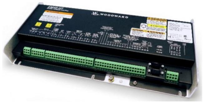
2301E-ST steam turbine control: There are two types: normal position and hazardous zone 2, with part numbers 8273-1013 and 8273-1014, respectively. The document refers to product specification 03407 and manual 26694.

Turbine control: 2301E-HT model is suitable for Francis turbine, 24VDC, normal position, part number 8237-2046, document reference product specification 03459 and manual 35092.

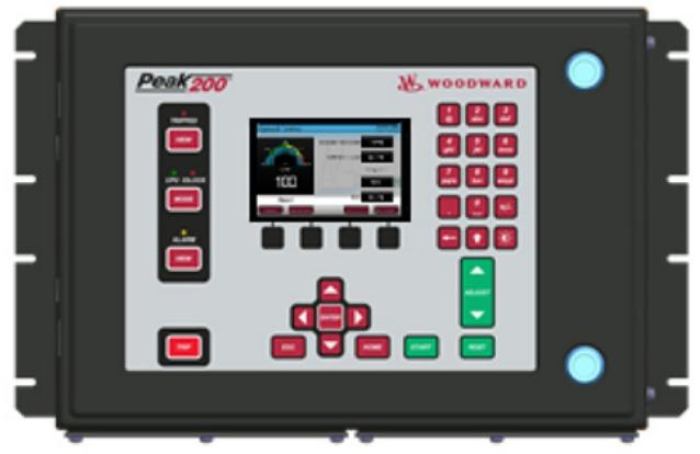
Peak200 steam turbine control: There are multiple installation methods and voltage specifications, such as LV type part number 8200-1500 for cabin wall installation, HV type part number 8200-1501 for front installation, etc. Refer to product specification 03438 and manual 35051 for documentation.

505 steam turbine control: including different voltage and position types, such as LVDC common position part number 8200-1300, HVAC/DC common position part number 8200-1301, etc., as well as 505-XT and 505-DR series. Refer to product specification 03422 and relevant manuals for documentation.

5009XT Steam Turbine Control: Depending on the power supply, there are three types: 2120V AC/DC, 220VAC, and 24VDC, with part numbers 8262-1141, 8262-1142, and 8262-1143. Accessories include a touch screen and software license.

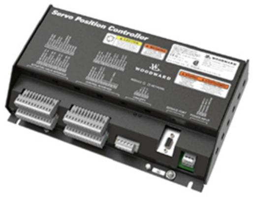
Servo position controller: can replace digital remote final drives, such as the configurable servo/actuator drive part number 8200-226 certified for marine use, and part number 8200-227 with CANOpen communication.

ProTech overspeed protection device: including ProTech SX, ProTech GII, ProTech TPS, MicroNet safety module, etc., with different installation methods and relay configurations, part numbers such as ProTech SX panel installation HV/LV type 8237-1242, ProTech GII cabin wall installation HV/LV independent relay type 8237-2594, and conversion kit.

Compressor control and related equipment

Vertex controllers: available in different voltage and compliance types, such as compressor control part numbers 8200-1370 for 18-36VDC standard compliance, 8200-1371 for 88-264VAC or 90-150VDC standard compliance, etc. Accessories include distributed I/O modules and remote viewing software licenses.

Electronic control

2300E electronic load sharing and speed control: available in hardware only version, with part numbers 8273-1017 for regular location and 8273-1018 for hazardous area 2. Refer to product specification 03405 and manual 26691 for documentation.

Flex500 platform: There are different installation methods and voltage types, such as front mounted LVDC with OCP part number 8200-1343, back mounted HVAC/DC part number 8200-1354, etc. Accessories include core source license and communication module.

MicroNet system modules, cables, and accessories:

Chassis: such as 8-slot MicroNet Plus chassis part number 5453-829, TMR chassis part number 5453-279.

Power supply: including MicroNet Plus power supply with 24VDC, 110VAC/125VDC, 220VAC input, and TMR power supply.

CPU modules: such as 5200CPU MicroNet TMR part numbers 5466-1347 and 5466-1247, MicroNet Plus P1020 CPU part number 5466-1511.

Communication module: such as RTN to CAN gateway part number 8200-1250, remote RTN part number 5466-1146.

Input/output module: including speed sensor, pressure interface, actuator driver, etc., such as 4-channel speed sensor part number 5466-5000, 2-channel actuator driver part number 5501-1428.

LINKnet HT and RTCnet modules: For example, RTD inputs 8-channel part numbers 8200-1200 and 8200-1100, and thermocouple inputs 8-channel part numbers 8200-1201 and 8200-1101.

Dataforth I/O: including K-type thermocouple, 100 Ω RTD, 4-20mA input, and 0-5VDC input module, part numbers such as 1784-1028, 1784-655, etc.

Network switch: 8-port Ethernet switch part number 1711-1350.

Cables: including NetCon analog and discrete cables, Ethernet Cat-5 cables, MicroNet TMR cables, etc., such as 6-foot NetCon analog cable part number 5416-346, 3-foot NetCon discrete cable part number 5416-332.

MicroNet TMR and Plus hardware kits: such as TMR hardware kits with 4565-1115 part numbers 8262-1145 to 8262-1150, standard MicroNet+kit part numbers 8262-3183, etc.

Magnetic pickups and active proximity probes: Magnetic pickups have different threads, lengths, and resistances, such as MPU-70 VPP part number 202816, MPU-50 VPP part number 1680-613; Active proximity probes such as 5-24VDC part number 1680-986 and 7-30VDC part number 1689-1114.

Software License

GAP software program: GAP-Reader does not require a license, Monitor GAP license part number 8928-5007, Editor GAP 4. X license part number 8928-5359.

The latest ITCC software core includes ASC1 to ASC4 anti surge control, STC steam turbine core, etc., with part numbers such as 5418-3675 to 5418-3678, 10-027-206, etc.

GUI development and viewing program licenses: CIS annual subscription license part number 1796-3131, RemoteView license part number 8928-5311, iFix HMI software licenses such as 1796-3132 and 1796-3145.

Software service tool programs and suites: Control Assistant license part number 8928-5014, ToolKit developer license part number 8928-5016, AppManager data log retrieval enterprise license part number 8928-5009.

NetSim simulation license: NetSim nVe Nodes Only license part number 8928-5363, Advanced license part number 8928-5364, and annual subscription license.

Remote access program: Site Manager Module part number 1711-1418, LinkManager license part number 8928-5347, GateManager setup and support fees.

Electro hydraulic governor and actuator

TG turbine governor: such as TG13 and TG17 series, with different speeds, rotation directions, and droop rates, part numbers such as TG13 screw 2400rpm CCW rotation ATEX part number 9904-814, TG17 screw 2400rpm CCW rotation ATEX part number 9904-800.

TG611: Includes conversion kit and different specifications of speed controllers, such as TG611-13 screw 2400rpm CCW with OTD part number 8516-175.

TGE turbine actuator: There are 2400rpm, 4000rpm, 6000rpm according to different speeds, with part numbers such as TGE13 2400rpm part number 9904-110.

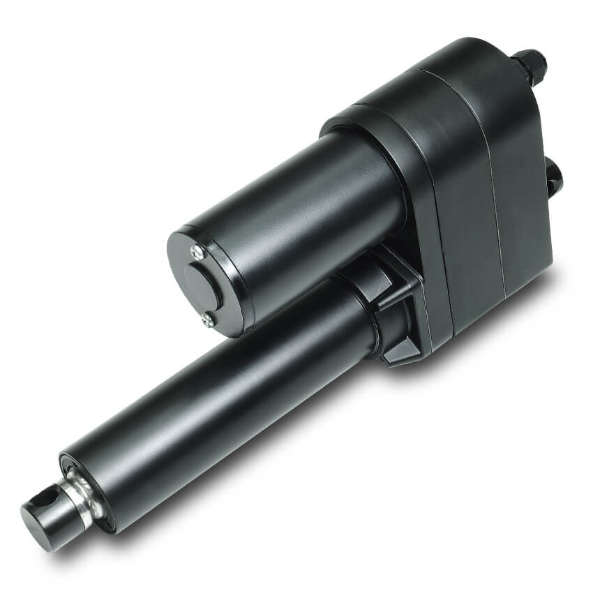
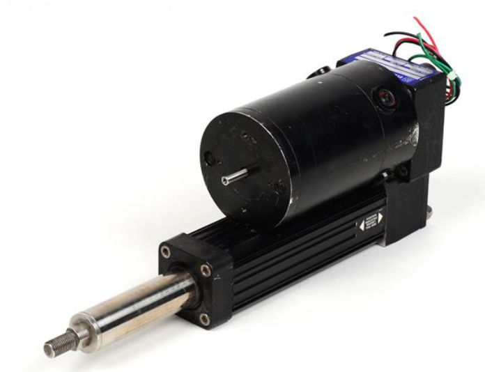
VariStroke actuator: It needs to be selected according to the model number, with double acting and single acting options. The part number is V45TD-2015-FUXM-X-S-X, part number 9907-1338, as well as VS-I, GI, DX servo and spare parts kit.

UG25+steam turbine governor and actuator: governor part numbers such as 8528-122 to 8528-137, actuator part numbers such as 8528-027 to 8528-327.

UG actuators: such as UG2 MPU CW dual lip drive seal part number 8251-212, UG15 series part number 8251-719, etc.

CPC-II current pressure converter: available in different pressure and area levels, such as 10Bar Class1 Div2 part number 9907-1200, 25Bar Class1 Div1 part number 9907-1197, and CPC-DX redundant kit.

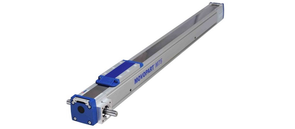
TM linear actuator: such as TM-25LP single coil extension part number 9907-1213, TM-200LP single coil retraction part number 9907-1225.

Turbine shutdown trip block components: The QuickTrip series is SIL-3 certified, with part numbers 0-9907-2108 for regular positions and 1-9907-2108 for Zone 1&2 positions. Spare parts include specialized tool kits and solenoid valve replacement kits.

Gas turbine valve

GS40 and GS50 gas fuel valve actuators: with onboard drivers, GS40 comes in 1.5-inch RF600 # and SAE specifications, part numbers such as 9908-1608 to 9908-1654; GS50 comes in 2-inch RF600 # and SAE specifications, with part numbers such as 9908-1605 to 9908-1673.

LQ6 liquid fuel valve actuator: The part numbers are 9908-1519, 9908-1520, and 9908-271 depending on the port size.

LQ25 standard valve: such as 0.1 square inch with PIV and SOV part number 9908-238, 0.2 square inch part number 9907-696, 0.3 square inch part number 9907-996.

LSOV25 liquid fuel shut-off valve: available in 24VDC and 125VDC, with proximity switch, part numbers such as 9908-359, 9908-358, 9908-363, 9908-361.

USOV universal shut-off valve: 2-inch 900 #, 1.6ACD, 24VDC part number 9907-1233.

GSOV80 and GSOV25HT gas fuel shut-off valves: GSOV80 is 3-inch HP, 24VDC and 125VDC, part numbers 9907-2328, 9907-2335; GSOV25HT has 24VDC and 125VDC, with on/off position switch, part numbers such as 9907-861 to 9907-899.

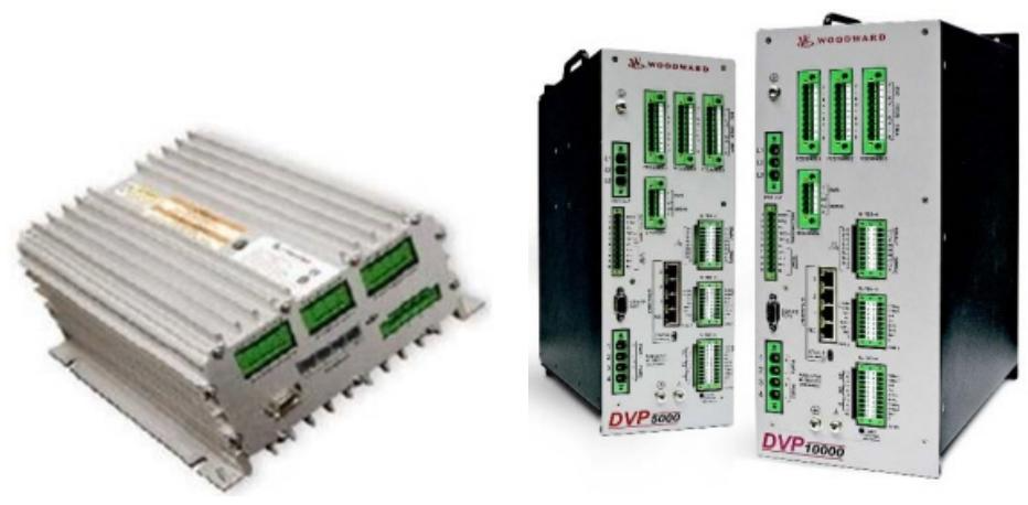
DVP digital valve positioner: available in 24VDC and 125VDC, with different protection levels and output powers, such as 24VDC IP30 TB input/output part number 8200-507, high output 5KW part number 8200-538, 10KW part number 8200-536, 12KW part number 8200-556.

L series actuators and integrated speed control

L series speed control – actuator only: part number 8404-7101, similar to 8404-536 and 8404-1001.

L series speed control – with ITB actuator: Depending on the ITB size, such as 36mm part numbers 8404-2007 and 8404-7, 43mm part numbers 8404-2008 and 8404-7, 50mm part numbers 8404-2009 and 8404-2033.

L series process control – with ITB: including air-fuel ratio control, such as 16mm trim valve part numbers 8404-3001 and 8404-7301, 22mm part numbers 8404-3002 and 8404-7302, and sealed ITB such as 25mm part numbers 8404-2035 and 8404-2061.

L series speed control – with ITB and Venturi mixer (MAS): such as LC50 25mm ITB part number 8404-4001, 30mm ITB part numbers 8404-4002 to 8404-4009 and 8404-7405 to 8404-7409.

L series diesel actuator applications: such as Stanadyne cover/shaft speed control part numbers 8404-563 and 8404-7503, Delphi cover/shaft with lever part numbers 8404-5004 and 8404-7504.

L series with ITB locator: such as 16mm fine adjustment valve part numbers 8404-3003 and 8404-7303, 22mm part numbers 8404-3004 and 8404-7304, sealed ITB such as 25mm part numbers 8404-2013 and 8404-7213.

L series accessories: including gaskets, HEGO sensors, cables, and communication interface kits, such as 16&22mm gasket part number 3051-073, HEGO sensor part number 1680-6005.

F-series actuators and actuators with ITB

F-series locator: There are different ITB sizes and installation methods, such as 33mm ITB standard installation 23 pin part number 8245-027, 48mm ITB standard installation 23 pin part number 8245-052, 60mm ITB standard installation 23 pin part number 8245-003, 68mm ITB standard installation 23 pin part number 8245-004. Accessories include 14 pin and 23 pin mating connector kits.

R series actuators

R-series actuators: R-11, R-30, R-120 electric positioners, R-11 is suitable for fuel racks, part number R11 positioners are not preferred 8410-001, replace 8410-007; R30 locator replacement 8410-008; R120 locator 8410-010.

ProAct actuator

ProAct 75 Speed Control (First Generation): Old part number such as 8400-010, new part number 8400-059, including driver and ITB, such as driver part number 8400-706, ITB part number 8235-399.

ProAct locator (16 pin, third-generation): Model II part number 8404-302, Model III part number 8404-303, Model IV part number 8404-304.

ProAct locator (Flex I/O): such as GEN3 FLEX Model II part numbers 8404-307, 8404-317, 8404-319, Model III part numbers 8404-308, 8404-318, Model IV part numbers 8404-309, 8404-315, etc.

ProAct ITB (3rd generation): 105mm ITB part number 8335-003120mm ITB part number 8335-004135mm ITB part number 8335-005.

TecJet fuel control valve

TecJet fuel control valve: suitable for different systems, such as TecJet 52 part number 8407-605 for EGS-01, part number 8407-603 for EGS-02/E6, Jenbacher specific part number 8407-636, CAT specific part number 525-8021, as well as TecJet 85 and 110 series.

DANAHER MOTION 522S65URL6000/522S65URL6000

Product overview

DANAHER MOTION 522S65URL6000/522S65URL6000  Linear guide rail is a core mechanical component specially designed for high-precision and high load industrial applications. Relying on DANAHER MOTION’s profound technical accumulation in the field of motion control, this linear guide achieves stable and reliable linear motion guidance function through innovative design and precision manufacturing processes, providing a solid motion foundation for automation equipment, CNC machine tools, semiconductor manufacturing equipment, etc., effectively improving the operational accuracy of equipment. Automation equipment, CNC machine tools, semiconductor manufacturing equipment, etc. provide a solid motion foundation, effectively improving the operational accuracy and stability of equipment.

Specification parameters

522S65URL6000 Profile Rail, 500 Series Roller Rail, 6000 mm Long

Size: 65 mm, Super Precision Grade, U Style, Steel, X=75 mm

522S65URL6000 Profile Rail, 500 Series Roller Rail, 6000 mm Long, Size: 65 mm

Super Precision Grade, U Style, Steel, X=75 mm

Ball/Roller:Roller 

Carriage/Rail/Assembly:Rail 

Grade:Super Precision 

Material:Steel 

Rail Size (nominal):65 mm

Style Name:U – Bolt up from bottom 

Temperature Max:80 °C

Temperature Min:-40 °C

Core Technology and Working Principle

Rolling element design: Precision balls or rollers are used as rolling elements internally, forming rolling friction between the guide rail and the slider. Compared to sliding friction, rolling friction greatly reduces motion resistance, allowing the slider to easily slide on the guide rail while reducing wear and extending the service life of the linear guide rail. During the movement of rolling elements, the uniform distribution of pressure effectively improves the load-bearing capacity and motion stability of linear guides.

Loop system: It has an efficient rolling element loop system. When the rolling element rolls between the slider and the guide rail to a certain position, it will return to its initial position through the loop channel, forming a continuous and continuous loop motion. This cyclic design ensures that the linear guide can work continuously and stably, even under long-term, high-frequency operating conditions, maintaining good performance.

Pre tightening technology: Advanced pre tightening technology is used to eliminate clearance during movement by adjusting the gap between the slider and the guide rail. Appropriate pre tightening force not only improves the rigidity of the linear guide rail, making it less prone to deformation under load, but also enhances the smoothness and accuracy of the movement, ensuring that the equipment can achieve precise positioning during operation.

Core advantages

High rigidity and stability: The 65mm wide guide rail design and precise structural layout endow this linear guide rail with extremely high rigidity. When subjected to large loads and impacts, it can maintain stable shape and position, effectively reduce vibration and deformation, and provide reliable guarantee for the high-precision operation of equipment. Whether in high-speed motion or low-speed precision machining processes, it can ensure the stability of motion and improve the quality of product processing.

Long lifespan and low maintenance: High quality material selection and exquisite manufacturing processes make linear guides have excellent wear resistance and fatigue resistance. The good fit between the rolling element, guide rail, and slider reduces the occurrence of wear and extends the service life of the product. At the same time, its simple structural design and good sealing performance reduce maintenance difficulty and frequency, reducing maintenance costs and downtime for enterprises.

High precision motion: With high-precision manufacturing processes and advanced pre tensioning technology, this linear guide can achieve micrometer level motion accuracy. In precision machining equipment, it is possible to accurately control the motion trajectory of the tool or worktable, ensuring the dimensional accuracy and surface quality of the machined parts; On the automated assembly line, precise positioning of the robotic arm can be ensured, improving assembly efficiency and product qualification rate.

Flexible installation and adaptability: The design fully considers the installation requirements of different devices, providing multiple installation methods and interface options for users to install and debug according to actual situations. At the same time, it can adapt well to various types of motors, drivers, and other mechanical components, and is widely used in various industrial automation equipment, with strong versatility and flexibility.

Application scenarios

In the field of CNC machine tools, it serves as a motion guiding component for worktables and cutting tools in CNC lathes, milling machines, machining centers, and other CNC machine tools. High precision linear guides can ensure precise linear motion of machine tools during the machining process, ensuring the dimensional accuracy and surface smoothness of machined parts, improving the machining efficiency and quality of machine tools, and meeting the demand for precision part machining in high-end manufacturing industries such as aerospace and automotive manufacturing.

Automated production line: applied to the material handling, assembly and other processes of automated production lines. For example, on an electronic product assembly line, linear guides can drive robotic arms to move quickly and accurately between different workstations, achieving automatic grabbing, placement, and welding of electronic components, improving production efficiency and product quality stability; On the automotive parts production line, it is used for motion guidance of conveyor lines and assembly equipment to ensure accurate transportation and assembly of parts.

Semiconductor manufacturing equipment: In the process of semiconductor chip manufacturing, high precision and stability are required for the equipment. DANAHER MOTION 522S65URL6000/522S65URL6000 linear guides can be applied in equipment such as lithography machines and etching machines, providing precise linear motion guidance for wafer transport and positioning, ensuring the accuracy and reliability of chip manufacturing processes, and promoting the development of the semiconductor industry.

Medical devices: play an important role in medical equipment such as CT scanners and surgical robots. In CT scanners, linear guides are used to control the precise movement of the scanning bed, ensuring that patients can be accurately positioned at designated locations during the scanning process and obtaining clear and accurate imaging data; In surgical robots, stable guidance is provided for the movement of the robotic arm, enabling precise surgical operations and improving surgical safety and success rates.

​Installation and maintenance precautions

Installation precautions

Before installation, it is necessary to ensure that the installation surface is clean, flat, free of oil stains, impurities, and protrusions to avoid affecting the installation accuracy and operational performance of the linear guide rail. Use professional measuring tools to inspect the installation surface to ensure that its flatness and straightness meet the requirements.

According to the requirements of the product manual, use appropriate installation tools and methods for installation. During the installation process, pay attention to the installation direction of the guide rail and slider to ensure correctness. At the same time, tighten the installation screws evenly to avoid deformation of the guide rail or jamming of the slider due to uneven force.

After installation, perform necessary debugging and inspection. Check whether the slider slides smoothly on the guide rail and whether there is any jamming phenomenon; Check if the accuracy of the linear guide meets the requirements, and adjust it promptly if there is any deviation.

Maintenance precautions

Regularly clean the linear guide rail to remove impurities such as dust, oil, and metal debris from the surface, preventing them from entering the interior of the guide rail and slider and exacerbating wear. When cleaning, a clean soft cloth or specialized cleaning agent can be used for wiping.

Lubricate the linear guide according to the prescribed cycle, using appropriate lubricants such as lithium based grease or lubricating oil. When lubricating, ensure that the lubricant is evenly applied to the contact surface between the guide rail and the slider to reduce friction and wear, and extend the service life of the linear guide rail.

Regularly check the accuracy and operating condition of the linear guide, observe whether the movement of the slider is smooth, and whether there are any abnormal noises or vibrations. If any problems are found, they should be repaired or replaced in a timely manner to avoid the problem from escalating and affecting the normal operation of the equipment.

Linear Guide Rail w/ Steel Rods - Redi-Rail RR14-024.000 Width: 34mm L ...

DANAHER MOTION TG10K259-A00X3 16 / TG10K259A00X316

Product overview

DANAHER MOTION TG10K259-A00X3 16 / TG10K259A00X31 6  Linear units are high-precision linear motion execution components designed specifically for industrial automation scenarios. This series of products achieves precise control of linear displacement through the integration of servo/stepper drive technology and precision mechanical transmission structure, and can be adapted to fields such as semiconductor manufacturing, medical equipment, and precision machining that require strict motion accuracy. As a moving component of MOVOPART, its core advantage lies in the high integration of electrical control and mechanical transmission, reducing system integration complexity.

Technical parameters and structural characteristics

(1) Core technical parameters

Travel range:

The TG10K259-A00X3 16 model has a stroke of 160mm (or 16 inches), while the TG10K259A00X31 6 model has a stroke of 60mm (or 6 inches). Please refer to the actual product labeling for details.

(2) Mechanical structure design

Guidance system:

Integrated high rigidity linear guide rail, supporting load eccentricity compensation, ensuring smooth motion, suitable for high dynamic response scenarios.

Protection level:

The main body shell is treated with aluminum alloy anodizing, with an IP54 protection level (optional IP65), which can resist dust and liquid splashes.

Application scenarios

(1) Industrial automation production line

Semiconductor manufacturing: X/Y-axis platform for wafer handling robots, compatible with cleanroom certified models, meeting Class 100 clean environment requirements.

Electronic assembly: Control the precise positioning of the suction nozzle in SMT surface mount equipment, with a positioning accuracy of ± 0.01mm, suitable for 01005 ultra micro component mounting.

(2) Medical devices

Medical imaging equipment: The CT/MRI equipment’s examination bed translation mechanism supports low-speed smooth movement (below 0.1mm/s) to reduce patient discomfort.

Surgical robot: The end linear displacement unit of the minimally invasive surgical robotic arm has a response time of less than 10ms and meets sub millimeter level operational accuracy.

(3) Precision machining

Numerical Control Machine Tool: As a Z-axis feed unit, it is equipped with servo drive to achieve high-speed cutting (feed rate ≥ 10m/min), with surface roughness Ra ≤ 0.8 μ m.

Laser processing: Control the two-dimensional scanning motion of the laser head, support G-code programming, and adapt to complex trajectory processing requirements.

Integration and Control Solutions

(1) Driver adaptation

Servo drive scheme:

Can be paired with DANAHER MOTION B8961/B8962 servo controllers, supporting position/speed/torque three loop control, compatible with ± 10V analog or pulse train input.

Stepper driven solution:

Compatible with SmartStep series drivers, supports micro step subdivision (up to 256 micro steps), reduces operational vibration, and is suitable for cost sensitive scenarios.

(2) Electrical interface

Encoder feedback:

Standard 2000 line incremental encoder (optional 17 bit absolute encoder), interface type RS422 differential signal.

I/O control:

Supports origin/limit switch input (NPN/PNP compatible), with output signals including collector open circuit signals such as motion completion and fault alarm.

Key points for installation and maintenance

(1) Installation precautions

Mechanical installation:

Use a torque wrench to fix the installation screws at the rated torque ([X] N · m), ensuring that the parallelism between the guide rail and the installation surface is ≤ 0.05mm/m.

Electrical connection:

The power lines of the driver and linear unit need to use shielded cables, and the encoder line should be routed separately to avoid electromagnetic interference.

(2) Maintenance cycle

Lubrication and maintenance:

Every 1000 hours or 6 months of operation, replenish lithium based grease (model [X]) through the oil nozzle to reduce wear on the guide rail and screw.

Accuracy calibration:

Every year, use a laser interferometer to calibrate the positioning accuracy. If the error exceeds ± 0.1mm, check the pre tightening force of the screw or the wear of the guide rail.

Model Supplement

TG10K259-A00X3 16

TG10K259A00X31 6

TG10K259-B00X3 25

Training | Thomson

DANAHER MOTION 2AB16ARBTL/2AB16ARBTL Linear actuator

Product overview

DANAHER MOTION 2AB16ARBTL/2AB16ARBTL linear actuator mechanical components are core products under the DANAHER MOTION brand that focus on linear motion control. This component efficiently converts electrical energy into linear motion mechanical energy through precise design and manufacturing processes, providing stable and accurate linear drive solutions for various mechanical equipment. With its excellent performance and reliable quality, it is widely used in various high-end manufacturing fields such as industrial automation, aerospace, medical equipment, etc., and has become an important component in achieving automated production and precise operation.

Linear Unit, 2AB, 1.000 in, Ball Screw Drive, Ball Guide, 0.0002 in Repeatability, Preloaded, Single Standard Carriage, 1.000 in Travel Per Shaft Rev, Shaft On Both Sides

DC control products

(1) D2403 controller

Application scenario: Suitable for positioning applications that require simple linear telescopic motion and variable speed control, and can easily interface with external devices such as PLC and input/output cards.

Power requirements: 105-125 VAC or 208-245 VAC, 50/60 Hz, maximum current of 2 A and 1 A respectively.

Motor output: 0-28 VDC, maximum 10 A (adjustable current trip: 0-10 A), rated continuous current of the motor is 4.5 A, peak value is 10 A.

Input/output: 6 optocoupler inputs, 4 open collector outputs, supports DIP switch programming, has timer function, variable speed range of 15:1, PWM frequency of 2000 Hz.

Environmental conditions: working temperature 0 ° C-50 ° C, storage temperature -40 ° C-85 ° C.

(2) D2502B controller

Application scenario: As a simulated position control, it accepts simulated voltage or current command inputs and is used in conjunction with an electric cylinder containing a linear potentiometer (- L option) to form a closed-loop linear positioning system.

Power requirements: 105-125 VAC or 208-245 VAC, 50/60 Hz, maximum currents of 2 A and 1 A respectively (jumper optional).

Motor output: 0-28 VDC, maximum 5 A (adjustable clamp: 0-5 A), rated continuous current of the motor is 4.5 A, peak value is 10 A.

Input and output: Supports three remote analog command signals: 0-5 VDC, 0-10 VDC, and 4-20 mA, with stop and disable inputs, dedicated stall output, LED indicator light monitoring system operation, variable speed range of 15:1, PWM frequency of 2000 Hz.

Environmental conditions: working temperature 0 ° C-50 ° C, storage temperature -40 ° C-85 ° C.

Servo control products (B8961/B8962)

Application scenarios: Suitable for TN-B and TC2, 3, 4, 5-B precision linear actuators, rodless linear actuators, and linear sliding tables/systems, capable of controlling position, speed, and force/torque, suitable for clamping, pressing, drilling, and automatic fastening applications.

Power input: 90-240 VAC single-phase, 50/60 Hz, B8961 maximum 1150 VA (115 VAC) or 2300 VA (230 VAC), B8962 current and power doubled.

Motor output: continuous 5 A, peak 10 A, protection functions include phase to phase short circuit and ground short circuit protection, and melting.

Encoder Input: Differential Orthogonal Incremental Encoder, maximum rate 2 MHz (orthogonal), powered by+5V @ 200 mA.

Other features: 6K memory (optional 30K, 400 programs), user adjustable position, velocity, and acceleration, support for descriptive variables, mathematical and conditional branches, high-speed interrupt driven input registration, B8962 supports linear interpolation vector movement, includes application development software, optical compatible I/O supports OPTO-22 (G4) digital module and Grayhill (G5) analog and temperature module.

Environmental conditions: If the working temperature of the radiator exceeds 55 ° C (131 ° C), it will shut down, and the humidity is 0% -90% non condensing.

Step control product (SmartStep)

Application scenarios: Suitable for TN-S/P and TC2, 3, 4, 5 S/P precision linear actuators, rodless linear actuators, and linear sliding tables/systems, with features such as high throughput, easy integration, small panel space occupation, and smoother motion curves.

Power input: SmartStep is 90-120 VAC single-phase, 50/60 Hz, maximum 500 VA (7.9 A setting); SmartStep-240 is 100-240 VAC single-phase, 50/60 Hz, with a maximum of 500 VA (3.9 A setting).

Motor current: SmartStep 0-7.9 A, increments of 0.1 A; SmartStep-240 0-3.9 A, increments of 0.1 A.

System resolution: 36000 steps per motor rotation, compatible with 2-phase hybrid permanent magnet motors, with inductor amplifier ranges of 2-60 mH and 8-240 mH, switch frequency of 20 kHz, and multiple protection functions such as short circuit, undervoltage, overtemperature, interlock, regeneration/overvoltage protection. Supports current setting (rest and idle modes), and software selectable current waveform.

I/O and diagnostics: 8 programmable inputs (limit, origin), compatible with 12 VDC or 24 VDC, optically isolated; Incremental encoder optical isolation, differential line driven 5 VDC signal, maximum frequency 2 mHz (orthogonal); 8 programmable open collector outputs, compatible with 12 VDC or 24 VDC, optically isolated, with a maximum output of 100 mA per output and a total charging current of 350 mA; LED indicates green (normal operation), red (fault), amber (flashing fault).

Environmental conditions: When the current is set to 6 A, the maximum ambient temperature is 50 ° C (122 ° F), the storage temperature is -40 ° C -80 ° C (-40 ° F -176 ° F), and the humidity is 0% -90% non condensing.

Other options and accessories

OPTO boards: The OPTO44 board can accommodate up to 8 OPTO modules (up to 4 inputs and 4 outputs); The OPTO88 board can accommodate up to 16 OPTO modules (up to 8 inputs and 8 outputs).

Breakout boards: DB25BO accessories convert DB25 I/O connectors on SmartStep into screw terminals; The SS-PNP BO breakout board converts the current output of SmartStep from charging to pulling.

Cables: SS-IO and SS-IO-6 are I/O cables that connect SmartStep to other devices or PLCs, with lengths of 2 feet and 6 feet respectively; SS-RS232 is a cable that connects SmartStep to a PC (9-pin communication port); PCS-5004 is a PC keyboard cable (excluding 5 VDC power supply) used for copying programs between the keyboard and PC.

Other accessories: FP220 is an optional programming keyboard/operator interface display; The EMC compatibility kit includes EMC-S6-1, etc.

DC LINEAR ACTUATORS - Linear Motion

DANAHER MOTION TG10K259-A00X3 46/TG10K259A00X34 6

TG10K259-A00X346 linear device, Movopart M100, ball screw drive, prism guide, 0.05 mm repeatability, non preloading, 3052 mm stroke, 3539 mm total length, single standard slider, 25 mm stroke per axis speed, single axis with keyway

TG10K259-A00X346 linear device, Movopart M100, ball screw drive, prism guide, 0.05 mm repeatability accuracy

No preload, stroke 3052 mm, total length 3539 mm, single standard slider, each axis speed 25 mm, single axis with keyway

Product overview

DANAHER MOTION TG10K259-A00X3 46/TG10K259A00X34 6 servo stepper motor driver is a key device under DANAHER MOTION, specially designed for high-precision motion control scenarios. It integrates advanced electronic technology and precise control algorithms, playing an important role in industrial automation, intelligent manufacturing, and other fields. It can provide precise, stable, and efficient power drive control for various mechanical equipment.

Working principle

Pulse signal reception and processing: This driver works like a sharp “signal receiver”, mainly by receiving pulse signals sent by external controllers. When these pulse signals arrive at the driver, the driver will precisely regulate the operation of the motor based on the number, frequency, and direction of the signals. For example, in an automated production line, the controller sends corresponding pulse signals to the driver based on the processing requirements of the product. The driver accurately interprets these signals and then commands the motor to make precise actions. If the motor needs to rotate a specific angle, the controller sends a corresponding number of pulses; To change the direction of motor rotation, it is achieved by changing the direction of the pulse signal.

Current and voltage conversion output: After receiving the pulse signal, the driver quickly converts it into current and voltage signals suitable for motor operation. This process is similar to a precise ‘energy conversion station’, carefully adjusting the output current and voltage based on the characteristics and operational requirements of the motor. Different types of motors have specific requirements for current and voltage, and this driver can intelligently adapt to ensure that the motor can obtain the appropriate power supply under various working conditions, and operate stably and efficiently.

Performance characteristics

High precision control: In terms of precision control, this driver performs excellently. It can control the positioning accuracy of the motor within a very small range, achieving micrometer level accuracy. In semiconductor manufacturing equipment, the machining accuracy of components is extremely high. With its high-precision control performance, this driver can accurately control the motor movement, ensuring that the equipment achieves precise characterization of chip patterns in processes such as photolithography and etching, and guaranteeing the manufacturing quality of semiconductor chips. This is thanks to its advanced subdivision technology, which can further subdivide the step angle of the motor, making the motor run more smoothly and the positioning more accurate.

Rapid response capability: It has excellent rapid response characteristics. When the external control signal changes, it can react in a very short time and quickly adjust the operating state of the motor. On an automated assembly line, the robotic arm needs to quickly and accurately grasp and place components. The driver can respond to control instructions in a timely manner, allowing the motor to quickly start, stop, or change speed, greatly improving assembly efficiency and reducing production cycles. Its rapid response mechanism is based on optimized circuit design and efficient control algorithms, which can quickly process signals and drive motors to perform actions.

Multiple control modes: To adapt to diverse application scenarios, a rich variety of control modes are provided. Common modes include position control mode, speed control mode, and torque control mode. In CNC machine tools, when machining parts, if precise control of the tool position is required, position control mode can be used; In the material conveying process, if the conveyor belt needs to run at a constant speed, the speed control mode can play a role; In some applications that require overcoming significant resistance, such as driving large machinery, torque control mode can ensure that the motor outputs sufficient torque. Users can flexibly switch control modes according to their actual needs, making the equipment run more in line with production requirements.

High reliability and stability: Reliability and stability factors are fully considered in the design and manufacturing process. High quality electronic components are used, and after strict quality testing and aging testing, they can operate stably in complex industrial environments. It can work normally in harsh environments with high temperature and humidity, as well as in places with strong electromagnetic interference, effectively reducing equipment failure rates and minimizing production interruption losses caused by equipment failures for enterprises. The internal circuit design has good anti-interference ability, which can shield external interference signals and ensure the stable operation of the driver and motor.

Danaher Motion Pacific Scientific Motion Ctrl K32HCHK-LNK-NS-00 Stepper ...

DANAHER MOTION 146U-3 / 146U3

DANAHER MOTION 146U-3/146U3 is not a transformer in the traditional sense. From its electrical parameters, working principle, and application scenarios, it focuses more on the field of motion control, mainly used for precise control of equipment motion, such as displacement of robotic arms, feed of machine tools, etc. It has a fundamental difference from the functions of transformers used for voltage conversion and power transmission distribution. However, in practical industrial application scenarios, DANAHER MOTION 146U-3/146U3 may work in conjunction with transformers. For example, in industrial automation production lines, transformers can provide suitable voltage for the entire system, and DANAHER MOTION 146U-3/146U3 achieves precise motion control of production equipment based on this stable power supply.

Brand and company background

Superior Electric is a brand under Danaher Motion, a globally renowned manufacturer of stepper motor positioning systems. Over 40 years ago, it developed and obtained patents for Superior stepper motor products. Danaher Motion has extensive experience in the field of motion control and can customize motors for customers to meet specific design needs. Its products are widely used in multiple markets and fields such as semiconductor manufacturing, packaging, printing, industrial automation, testing and measurement.

Product Line Overview

(1) High torque stepper motor series

KM06 series (NEMA 23): 60mm frame size, available in multiple models such as KM060, KM061, KM062, KM063, Holding Torque range from 68 oz in (48 N-cm) to 350 oz in (247 N-cm), suitable for applications requiring moderate torque.

KM09 series (NEMA 34): 90mm frame size, including KM091, KM092, KM093, with higher Holding Torque ranging from 385 oz in (272 N-cm) to 1155 oz in (816 N-cm), suitable for industrial environments with high torque requirements.

KM11 series (NEMA 42): With a frame size of 110mm, available in KM111, KM112, and KM113, the Holding Torque has been further improved, ranging from 1450 oz in (1020 N-cm) to 3750 oz in (2650 N-cm), to meet applications with high torque requirements.

MH172 series (NEMA 66): With a frame size of 170mm and a Holding Torque of up to 5330 oz in (3764 N-cm), it is an ideal choice for high torque requirements.

(2) Electric motors for hazardous environments

MX09 series (NEMA 34): Suitable for hazardous environments, compliant with UL Class 1, Division 1, Group D standards, and available in multiple models to meet different load requirements.

MX11 series (NEMA 42): also designed for hazardous environments, with high torque and reliability.

(3) Accessories and Options

Encoder: Provides various specifications such as 200, 400, 500, 1250 lines/rpm, which can be used for position feedback and accuracy control.

Gearbox: Can be paired with an electric motor, providing a transmission ratio of 3:1 to 100:1 to meet different speed and torque requirements.

Other options: including double ended shafts, terminal boxes, special windings, etc., can be customized according to customer needs.

Technical features and advantages

High precision: The stepper motor has an inherent step angle of 1.8 ° (200 steps per revolution), which can be further subdivided through micro step driving. The positioning accuracy can reach ± 2% (NEMA 23 and 34) or ± 5% (NEMA 42 and 66).

High torque: The torque of the new product line is twice or even more than that of traditional stepper motors, which can meet the requirements of high load applications.

Reliability: Adopting brushless design, high temperature resistant insulation material, stainless steel shaft, and long-life ball bearings to ensure stable operation in harsh environments.

Flexible control: supports full step, half step, and micro step operations, can adapt to different control requirements, and does not require complex feedback devices.

Efficient and energy-saving: Optimized design improves motor efficiency and reduces energy consumption.

Selection tools and methods

MOTIONEERING ®  Software: This is a free Windows based software that helps users easily choose the appropriate motor and drive system. It can automatically consider load, motor, and drive parameters, support multiple mechanical systems such as screw, gear rack, conveyor belt, etc., and provide project folder management function, making it convenient for users to share data.

Quick Selection Guide: An overview of the overall product is provided on page 5 of the catalog, arranged by frame size, with each section containing detailed motor specifications and speed torque curves for motor/drive system combinations, making it easy for users to compare and choose.

Application assisted computing: The directory provides detailed information on load torque and inertia calculation methods for different application scenarios, such as screw systems, cylinder/rod systems, disc/pulley systems, etc., to help users accurately determine motor requirements.

Typical application scenarios

Industrial automation: including automated production lines, material handling, picking and placing applications, etc., which can accurately control the movement of robotic arms and conveyors.

Medical devices, such as surgical robots and medical imaging equipment, require high-precision and reliable motion control.

Semiconductor manufacturing requires extremely high precision and stability in processes such as photolithography, etching, and wafer handling.

Packaging and Printing: Used for precise control of the movement of packaging equipment and printing machinery to ensure product quality and production efficiency.

Office equipment and robots: paper conveying systems such as printers and copiers, as well as joint drives for various robots.

Dangerous environment application: MX series motors can be used in hazardous environments with explosive gases or dust, such as petrochemical, coal mining and other industries.

DANAHER MOTION TG10K259-C35X3 81 / TG10K259C35X38 1

Product overview

DANAHER MOTION TG10K259-C35X3 81/TG10K25C35X381 is a product with important application value in the field of industrial automation. It has precise manufacturing processes and advanced technological design, and can provide stable and efficient motion control solutions for various complex industrial scenarios.

Brand background

DANAHER MOTION’s Danaher Group is a global innovator in science and technology. Danaher Group has a wide business layout worldwide and is committed to providing advanced solutions to numerous industries through continuous technological innovation and excellent product quality. It has accumulated profound technical expertise and rich industry experience in the field of motion control. Its DANAHER MOTION brand products have won a high reputation in the global market with high precision, high reliability, and excellent performance, and are deeply trusted by customers in various industries.

​Working principle

This product is based on the working principle of servo motors. It receives control signals from external inputs such as pulse signals and analog signals through a controller. After internal signal processing and conversion, it generates corresponding control instructions to drive the servo driver to work. The servo driver precisely adjusts the current, frequency, and phase of the servo motor according to control instructions, thereby controlling the motor’s speed, direction, and position. At the same time, the encoder installed on the motor will provide real-time feedback on the actual operating position and speed information of the motor to the controller. The controller continuously adjusts the control strategy by comparing and analyzing the feedback signal with the input command signal, achieving closed-loop precise control of the motor motion and ensuring the accuracy and stability of the equipment’s motion.

Key advantages

High precision positioning: With advanced sensing and control technology, as well as precise mechanical manufacturing processes, positioning errors can be controlled within a very small range. In application scenarios that require precision at the micrometer level, it can still perform stably and accurately complete various instructions, laying a solid foundation for the precise operation of equipment.

High load capacity: It can easily cope with different levels of load demands, maintain stable operation even under heavy loads, and ensure the continuous and efficient operation of equipment. It is suitable for industrial production environments with high load requirements.

Stability and reliability: After strict quality testing and practical application verification, it can adapt to various complex working conditions and harsh environments. Whether it is high temperature, high humidity, or strong electromagnetic interference environment, it can work normally, effectively reduce equipment failure rate, extend equipment service life, reduce maintenance costs and production interruption risks for enterprises.

Efficient and energy-saving: During operation, low energy consumption is achieved through optimized control algorithms and efficient motor design, which not only helps enterprises reduce energy costs but also conforms to the current trend of energy conservation and environmental protection.

Precautions

Installation precautions: During the installation process, it is necessary to strictly follow the installation instructions in the product manual. Ensure that the installation position of the equipment is flat and stable, and avoid vibration or displacement caused by improper installation during equipment operation, which may affect the accuracy and service life of the equipment. Meanwhile, when connecting various components, attention should be paid to aligning and fixing the interfaces to prevent looseness or poor contact.

Electrical connection: Strictly follow the electrical connection diagram in the product manual to ensure the accuracy and firmness of the wiring. Pay attention to the correct connection of the positive and negative poles of the power supply to avoid equipment failure or even damage caused by electrical connection errors. Before powering on, it is necessary to carefully check whether the electrical connections are correct. Only after confirming that there are no errors can the 

Power be turned on for operation.

Usage environment: Try to install the equipment in a dry and well ventilated environment, avoiding damp, dusty, or corrosive gas environments to avoid affecting the performance and lifespan of the equipment. At the same time, attention should be paid to the temperature range of the operating environment of the equipment, avoiding use at temperatures that are too high or too low, to ensure that the equipment can operate stably under suitable environmental conditions.

Maintenance: Regularly maintain the equipment, check whether the appearance of the equipment is damaged, whether the connecting parts are loose, and whether the motor is running normally. Clean, lubricate and maintain the equipment at regular intervals, replace vulnerable parts in a timely manner, and ensure that the equipment is always in good operating condition.

丹纳赫传动(中国)有限公司

Xycom 95212B-001 Module Circuit Board Card

Product Overview

Xycom 95212B – 001 Module Circuit Board Card, As a key component designed specifically for the field of industrial automation, it often works in conjunction with related models such as 95213-007 and 8503, playing a core role in programmable logic controller (PLC) systems. Its design aims to meet the stringent requirements for efficient data processing, precise control, and reliable operation in complex industrial environments. This circuit board achieves the acquisition, processing, and transmission of various industrial signals through carefully arranged circuit lines and high-performance electronic components, which is the foundation for ensuring the stable and efficient operation of industrial automation systems.

Technical specifications

(1) Interface type

It has a rich variety of interfaces, including but not limited to standard industrial communication interfaces such as RS-232, RS-485, and Ethernet interfaces. The RS-232 interface is suitable for short distance and low-speed data transmission scenarios, commonly used for connecting debugging equipment, sensors, etc., and can achieve reliable one-to-one communication. The RS-485 interface is widely used in industrial fieldbus networks due to its support for multi node connections, long transmission distances (up to 1200 meters), and strong anti-interference capabilities. It can connect multiple distributed devices and achieve centralized data collection and control. The introduction of Ethernet interface has greatly improved the data transmission rate, which can meet the communication requirements of high-speed and large amount of data, facilitate the access of equipment to the industrial Internet, and realize remote monitoring and management.

(2) Working voltage and power consumption

The working voltage range is DC 24V ± 10%, which is a common industrial voltage standard that ensures compatibility with most industrial power systems and has good voltage adaptability, enabling stable operation within a certain voltage fluctuation range. In terms of power consumption, the circuit board adopts a low-power design concept, with a typical power consumption of only [X] W (specific values need to refer to the product manual), effectively reducing energy consumption, reducing equipment heating, and improving system stability and reliability, especially suitable for industrial application scenarios that require energy efficiency.

(3) Storage and processing capabilities

Onboard high-performance microprocessor with powerful data processing capabilities, capable of quickly responding to and processing various signals from industrial equipment. Its computing speed can reach [specific computing speed, such as executing [X] instructions per second], ensuring precise and real-time control even in complex industrial control tasks. At the same time, it is equipped with sufficient storage resources, including [specific capacity, such as 64KB] random access memory (RAM), for temporary storage of running data and programs, ensuring the efficiency and smoothness of data processing; And [specific capacity, such as 256KB] flash memory, used to store important information such as system programs and configuration parameters, with the characteristic of not losing data in case of power failure, ensuring that the system can quickly recover to its previous working state after restart.

(4) Working temperature and humidity range

Considering the diversity of industrial environments, this circuit board has a wide operating temperature range and can operate stably in ambient temperatures ranging from -20 ℃ to 70 ℃. Whether in cold northern industrial plants or hot southern production workshops, it can work normally without being affected by temperature changes. In terms of humidity, it can adapt to environments with relative humidity ranging from 5% to 95% (without condensation), effectively avoiding problems such as circuit short circuits and corrosion caused by humid environments, ensuring reliable operation in humid industrial environments such as food processing workshops and chemical production sites.

Functional Features

(1) Data collection and processing

Capable of accurately collecting analog and digital signals from various industrial sensors. For analog signals, high-precision analog-to-digital converters (ADCs) are used to convert continuously changing physical quantities (such as temperature, pressure, flow rate, etc.) into digital signals with a conversion accuracy of up to [specific precision, such as 16 bits], ensuring the accuracy of data acquisition. When collecting digital signals, it can quickly identify and process signals with different level standards, such as TTL, CMOS, etc. The collected data is preprocessed inside the board to remove noise and interference, and then transmitted to the core processor of the PLC for further analysis and decision-making, providing a reliable data foundation for industrial automation systems.

(2) Communication control

As a key node in industrial communication networks, this circuit board supports multiple communication protocols, such as Modbus, Profibus, etc. As one of the most widely used communication protocols in the industrial field, Modbus protocol has the characteristics of simplicity, openness, and ease of implementation. This circuit board supports Modbus RTU and Modbus TCP protocols, making it easy to communicate with other Modbus devices and achieve data reading, writing, and device control. The Profibus protocol is widely used in industrial automation production lines and is suitable for communication scenarios that require high speed and real-time performance. This circuit board supports the Profibus DP protocol and can quickly and reliably exchange data with field devices, ensuring efficient operation of the production line. Through these communication protocols, the circuit board can upload the collected data to the upper computer monitoring system and receive control instructions from the upper computer, achieving remote monitoring and control of industrial equipment.

(3) Reliability Design

In order to adapt to harsh conditions such as electromagnetic interference, vibration, and impact in industrial environments, the Xycom 95212B-001 circuit board adopts a multi reliability design. In terms of circuit layout, electromagnetic compatibility (EMC) design principles are adopted, and measures such as reasonable wiring, shielding, and filtering are taken to effectively reduce the impact of electromagnetic interference on the circuit and ensure the stability of signal transmission. In terms of mechanical structure, the circuit board adopts a reinforced design, and the components are strictly screened and soldered to withstand a certain degree of vibration and impact, reducing the probability of failure caused by mechanical stress. In addition, the board also has a comprehensive self diagnostic function, which can monitor its own working status in real time. Once a fault is detected, an alarm signal is immediately issued and the fault information is recorded, making it convenient for technicians to quickly locate and troubleshoot the fault, ensuring the continuous operation of industrial automation systems.

Application scenarios

(1) Industrial automation production line

The Xycom 95212B-001 circuit board plays a crucial role in large-scale industrial automation production lines such as automobile manufacturing and electronic appliance production. It can connect various sensors (such as position sensors, pressure sensors, visual sensors, etc.) and actuators (such as motors, cylinders, solenoid valves, etc.) on the production line, collect various data in real time during the production process, such as the assembly position of components, equipment operation status, product quality inspection data, etc., and transmit these data to PLC for analysis and processing. Based on the analysis results, PLC sends control instructions to actuators through circuit boards to achieve precise control of the production process, ensuring efficient and stable operation of the production line, and improving product quality and production efficiency.

(2) Energy Management System

In energy management systems in industries such as electricity, oil, and natural gas, this circuit board is used to monitor and control key equipment in the process of energy production, transmission, and distribution. For example, in a power plant, sensors of various power generation equipment can be connected to collect real-time operating parameters of the generator (such as voltage, current, frequency, power, etc.), temperature and pressure data of the boiler, and transmit these data to the PLC of the energy management system. PLC achieves optimized control of power generation equipment, improves power generation efficiency, and reduces energy loss through data analysis. In oil and gas transmission pipelines, real-time monitoring of pressure and flow changes can be achieved by connecting pressure sensors, flow sensors, etc. Once abnormalities are detected, control instructions can be sent to relevant equipment through circuit boards in a timely manner to take emergency measures and ensure the safety and stability of energy transmission.

(3) Intelligent warehousing and logistics system

In intelligent warehousing and logistics systems, the Xycom 95212B-001 circuit board is used to control automated warehousing equipment (such as stackers, shuttles, conveyors, etc.) and logistics handling equipment (such as AGV automatic guided vehicles). By connecting sensors on the device (such as position sensors, speed sensors, cargo detection sensors, etc.), real-time operation status data of the device is collected and transmitted to the PLC. PLC sends control signals to equipment through circuit boards based on task instructions issued by the warehouse management system (WMS), achieving precise control of the equipment, completing operations such as storage, handling, and sorting of goods, and improving the automation level and operational efficiency of warehousing and logistics systems.

Installation and maintenance

(1) Installation steps

Before installing the Xycom 95212B-001 circuit board, it is essential to ensure that all related equipment is powered off and take anti-static measures, such as wearing an anti-static wristband, to avoid damage to the circuit board caused by static electricity. Firstly, according to the installation manual of the device, find the appropriate installation slot or interface position. Insert the circuit board card smoothly into the slot, ensuring that the gold fingers are fully in contact with the pins inside the slot, to avoid loosening or tilting. For the case of using external connection interfaces, use corresponding connection wires (such as communication cables, power cords, etc.) and connect the circuit board to other devices in the correct wiring method to ensure a firm and reliable connection. After completing the hardware connection, power on the device and check if the system can recognize the circuit board properly. If necessary, follow the device manual to set up the relevant software and install the driver.

(2) Maintenance points

Regularly clean the circuit board by using a clean and soft brush or compressed air to remove dust and debris from the surface of the board, preventing dust accumulation from affecting heat dissipation and electrical performance. Regularly inspect the components on the circuit board for any looseness, deformation, burning, or other abnormal phenomena, as well as the connecting cables for any damage, aging, or other issues. If any are found, repair or replace them in a timely manner. Pay attention to the working status of the circuit board during the operation of the device, such as whether there is abnormal heating, alarm indicator lights on, etc. If there is a malfunction, first refer to the equipment’s fault diagnosis manual, check the relevant hardware connections and software settings, and try to troubleshoot on your own. For more complex faults, it is recommended to contact Xycom’s professional technical support personnel or authorized repair institutions for maintenance. Do not disassemble the circuit board by yourself to avoid more serious damage. At the same time, regularly backup important data and configuration parameters in the equipment to prevent data loss due to circuit board failures.

-佛山市顺德善诺电子有限公司

Xycom 97951-025 2112-MD Option Module Component

Product overview

The Xycom 2112 expansion module is an additional module for 2000 series workstations, mainly used to connect PLC and other devices (via non-standard data cables, such as non RS-232C/422/485) or for memory expansion. There are two basic configurations for the module: with PLC communication module and without PLC communication module (only for memory expansion). When equipped with a communication module, it can communicate with PLCs or networks such as Allen Bradley Remote I/O, Modbus Plus, etc. It can also install 128Kx8 RAM or EPROM in socket U2 for memory expansion (RAM requires battery backup). This module is only applicable to specific 2000 series terminals, such as 2000, 2000T, 2005, etc.

Technical specifications

Environmental parameters: working temperature of 0 ℃ -50 ℃, non working temperature of -40 ℃ -60 ℃, humidity of 10% -80% (non condensing), resistance to 15g impact and 0.006 “peak to peak vibration during operation, resistance to 30g impact and 2.5g vibration during non operation.

Memory storage: Optional 128KB RAM or EPROM, RAM is backed up by battery when installed in 2000 series workstations.

Installation guide

(1) Components and Jumpers

Key components: including jumpers J1-J9, socket U2 (for memory expansion), connectors JK1 and P1.

Jumper settings: J1 is used to specify U2 as RAM (RRR) or EPROM (EE), J2-J4 is used in conjunction with J1 settings, and other jumpers (J5-J9) are factory fixed configurations and cannot be changed by the user.

(2) Memory expansion installation steps

Power off and remove the 2112 module.

Set J1 as RRR and J2-J4 as B.

Install RAM/EPROM chip in U2 socket (pay attention to pin alignment).

If installing RAM, set J2-J4 to A; if installing EPROM, set J1 to EE.

Reinstall the module and power it on to verify if the memory is available.

(3) Module installation to 2000 series

Turn off the power and remove the connector cover on the side/bottom of the terminal.

Align the P1 connector of module 2112 with the terminal interface and secure it with screws.

Ensure correct jumper settings (refer to the communication module appendix) and connect external device cables.

Appendix of Communication Module

(1) Allen Bradley Remote I/O interface

Hardware configuration: Six pin connector, red LED indicates not initialized, green LED indicates data transmission in progress. Jumper JB2 needs to be set to “Enable” to simulate the I/O rack, and switch SW1 needs to be set in specific positions (3 and 5 open, 1, 2, 4, and 6 closed).

Electrical connection: Use Belden 9463 dual axis cable (blue hose), connect the corresponding pins according to color, and the terminal requires a 150 Ω resistor or dual 75 Ω resistor for anti-interference.

SoftScreen configuration: Configure AB Remote I/O through port 2, set parameters such as baud rate, PLC type, and rack enable, and use specific expressions (such as [Address bit], [Address bit]) to read and write data.

(2) Modicon Modbus Plus interface

Network connection: Connect to Modbus Plus network through SA85 port, use twisted pair shielded cable, and ensure unique node address (SA85 switch 1-6 settings, address is switch binary value+1).

Memory base address setting: The base address range is C0000-EF800 hex, and the 2000 series needs to be set to D0000. Hardware interrupts can be set to polling mode through jumper wires.

Status indication: The flashing mode of the network indicator light indicates different statuses (such as 6 times/second for normal, 4 times/second for address conflict).

How to use Xycom 2112 expansion module?

Confirm compatibility: The Xycom 2112 expansion module is designed specifically for 2000 series workstations. Before use, it is necessary to confirm its compatibility with the selected 2000 series terminal. Compatible terminal models include 2000 (97957-001), 2000T (97957-101), 2005 (97958), etc. If the memory expansion function is used, 2112-MEM is only suitable for direct connection to OIL or Softscreen and is not applicable to basic terminal firmware.

hardware install

Preparation work: Prepare the Xycom 2112 expansion module, connecting cables, and necessary installation tools. Before installation, be sure to carefully read the installation guide for the 2112 expansion module and 2000 series workstation, familiarize yourself with the installation process and precautions.

Installation module: Turn off the power of the relevant equipment, follow the installation guide, and correctly install the 2112 expansion module to the corresponding position on the 2000 series workstation. This module is connected to the workstation through three rows of 48 pin connectors and secured with the four screws already provided. At the same time, connect the power line, signal line, and ground line (if required) according to actual needs, ensuring that the connection is firm and meets safety standards.

Memory expansion (optional): If memory expansion is required, power off the module before installation. Set the corresponding jumper according to whether RAM or EPROM is required for installation. When installing RAM, set J1 as RRR, and when installing EPROM, set J1 as EE and J2-J4 as B. Then, smoothly install the 128Kbytes RAM or EPROM chip into the U2 socket, paying attention to aligning pin 1 of the chip with pin 1 of the socket accurately. The installation process must follow electrostatic safety rules. After completing the chip installation, if RAM is installed, J2-J4 needs to be reset to A.

Communication configuration (for situations with PLC communication module)

Allen Bradley Remote I/O interface configuration: Use a Belden 9463 dual axis cable (blue hose) for connection, with the blue wire of the cable connected to pin 1 (or 4) of the PLC, the shielded wire connected to pin 2 (or 5), and the Clear wire connected to pin 3 (or 6). To simulate an I/O rack, set jumper JB2 to “Enable” and switch SW1 to a specific position (3 and 5 open, 1, 2, 4, and 6 closed). In the Softscreen system, configure ports by selecting the Application Load Configuration EdPorts Port 2 path and setting parameters such as AB Remote I/O network type, baud rate, PLC type, etc.

Modicon Modbus Plus interface configuration: Connect to the Modbus Plus network through the SA85 port using a network cable. Set the SA85 address, which must be unique in the network. Its value is the binary value set by switches 1-6 plus 1, and switches 7 and 8 are not used. At the same time, set the memory base address within the range of C0000- EF800 hexadecimal. For 2000 series engines, this address must be set to D0000. In addition, it is necessary to set the hardware interrupt jumper to polling mode to ensure normal communication.

Allen Bradley Data Highway Plus interface configuration: also uses Belden 9463 dual axis cable connection, with wiring similar to Allen Bradley Remote I/O. Set jumper JB2 to the enabled state and use specific address expressions (such as [O: addr/bit], [T file: element. acc/bit], etc.) for data read and write operations based on different file types. When configuring, it is also necessary to set parameters such as baud rate, mode (foreground mode or background mode), response timeout value, and station number to ensure stable communication with the PLC.

Software setup and testing

Set parameters: Use corresponding software tools (such as Softscreen Development System software) to set parameters for the extension module. These parameters include basic parameters such as the number, type, and address of input/output (I/O) points, as well as communication parameters such as baud rate, data bits, stop bits, parity bits, etc., if applicable. Parameter settings should be based on actual application requirements to ensure that the module can function properly.

Xtron Module Kit | 产品 | ovobot

Xycom Automation PL3115T Industrial Touch Monitor

Product Overview

Xycom Automation PL3115T Industrial Touch Monitor is a high-performance touch display designed specifically for industrial environments. In the current era of accelerating industrial automation, the requirements for human-machine interaction interfaces in industrial equipment are becoming increasingly stringent, requiring display devices that can operate stably and accurately under complex working conditions.

The PL3115T, with its 15 inch high-definition touch screen, stable data transmission performance, and excellent environmental adaptability, has become a bridge for efficient communication between industrial field operators and equipment. It can be widely used in industrial production line monitoring, mechanical manufacturing equipment operation, energy management systems and other scenarios, helping users to obtain real-time equipment operation information, conveniently set parameters and issue instructions, effectively improving the efficiency and safety of industrial production.

Xycom Automation industrial computers (IPCs) are designed to provide processing power and versatility.

The 3115T IPC offers a powerful processor with a wide range of features and an expansion slot.

The 3115T also meets the rigorous require ments of the plant floor with a high-resolution

flat panel display in a rugged housing ideal for today’s manufacturing environment.

Higher Performance

The 850 MHz Intel Pentium III CPU drives the fastest and most de manding applications.

Preloaded Operating Systems

All 3115T systems come standard with either Windows NT or Windows 2000. 

Windows 98 and MS-DOS are also avail able.

Sharp, Easy-to-Read Displays

A bright 15″ TFT screen can display complex op erations with clarity.

Full Complement of I/O Ports

The 3115T comes standard with an extensive array of I/O ports (see above), including three high-speed RS-232 ports, one configurable RS-232/422/485 port, two SPP/EPP/ECP parallel ports, two USB ports(one using DOS), one PS/2 mouse/keyboard port,one 10/100 Mbps Ethernet port (not available with DOS), one VGA port, and audio I/O (input, output,and mic). The PS/2 port can be connected to a mouse or a keyboard, or it can be connected to both using the supplied Y-cable.

The VGA port can be used to connect a VGA monitor, with or without using the built-in display (which

can be turned off). The built-in display and an external monitor can be used together in mirror mode

(both show the same image) or multi-monitor mode (both show different images).

Mounting Options

The 3115T is designed to be mounted directly into an equipment panel without requiring special

mounting plates or brackets. It can also be mounted on a wall with the wall-mount adapter included in the mounting kit or it can be mounted on a standard 75/100 mm VESA swing or pendent arm. 

The 3115T is not NEMA rated if mounted outside of a panel.

FEATURES 15” flat panel TFT XGA (1024×768) color display

Analog resistive touchscreen

850 MHz Intel ®  Pentium ®  III CPU with 100 MHz Front System Bus and 256 KB

cache 256 MB SDRAM (512 MB optional)

Video RAM configurable to 64 MB (uses system SDRAM)

VGA port for remote monitor

Dual view option to use remote monitor and built-in display simultaneously

Preloaded with MS-DOS ®,  Windows ® 98, Windows NT ®,  or Windows 2000

One half-length PCI expansion slot 20 GB 2.5″ hard drive, floppy drive

CD-ROM drive

Type II CompactFlash card slot (can accommodate IBM Microdrive )

Two RS-232 ports

One configurable RS-232/422/485 port

Two SPP/EPP/ECP parallel ports

Two USB (v.1.1) ports (one using DOS)10Base-T/100Base-TX Ethernet (not

available with DOS)Audio input/output/mic

PS/2 keyboard/mouse port (Y-cable included)

Software programmable watchdog timer 

Mounted with mounting clips or stan dard 75/100 mm VESA arm

Power cable and drivers included

Key advantages

(1) Convenient and efficient operation

Accurate touch operation and intuitive interface design enable operators to quickly get started and proficiently use without complex training. In industrial production, it can significantly reduce operating time and improve production efficiency. For example, in emergency situations, operators can quickly issue commands by touching the screen, promptly handle equipment failures or abnormal situations, and avoid losses caused by production interruptions.

(2) Strong compatibility and scalability

Multiple industrial standard communication interfaces and extensive protocol support endow the PL3115T with excellent compatibility. It can seamlessly integrate with mainstream industrial equipment and control systems in the market, making it easy to adapt to both new equipment integration and old system upgrades. At the same time, its open architecture also supports users to conduct secondary development according to their actual needs, add personalized functional modules, meet the diverse needs of different industrial scenarios, and save system integration costs and time for enterprises.

(3) High reliability and long lifespan

Strictly follow industrial standards for design and manufacturing, select high-quality electronic components and sturdy and durable housing materials, and undergo multiple rigorous tests such as high temperature, low temperature, vibration, electromagnetic interference, etc. In industrial production environments that operate continuously for a long time, the failure rate is low, which can effectively reduce equipment downtime and lower maintenance costs for enterprises. In addition, Xycom’s comprehensive after-sales service system can provide users with timely technical support and maintenance services, ensuring stable product operation and extending service life.

Precautions

(1) Installation requirements

Before installation, all power sources must be disconnected and anti-static equipment such as a wristband must be worn to prevent static electricity from damaging the internal components of the monitor. According to the instructions in the product installation manual, fix the monitor in the appropriate position to ensure a secure installation and prevent equipment loosening or damage caused by vibration or collision. The installation environment should be kept dry, well ventilated, and away from high temperatures, humidity, strong magnetic fields, and corrosive gas environments. When connecting communication cables and power cords, ensure that the interface is tightly connected and oriented correctly to avoid abnormal data transmission or equipment failure caused by poor contact or reverse connection.

(2) Usage standards

Non professionals are strictly prohibited from arbitrarily changing the hardware settings and software parameters of the monitor. If parameters need to be adjusted, professional technicians must follow the instructions in the product manual while the power is off. During device operation, avoid frequent plugging and unplugging of communication cables or other external devices to prevent instantaneous current surges from damaging internal circuits. Regularly use a clean, soft dry cloth to wipe the screen and housing, remove dust and stains, and do not use corrosive cleaning agents to avoid damaging the screen surface coating or housing material.

(3) Maintenance and troubleshooting

Regularly check the operation status of the monitor, including whether the screen display is normal, whether the touch operation is sensitive, and whether the communication is stable. If there are faults such as black screen, blurred screen, and unresponsive touch, first check whether the power connection and communication cable are loose or damaged, and try unplugging the cable again to solve the problem. If the fault persists, refer to the troubleshooting guide in the product manual for further inspection, such as checking device parameter settings, updating driver programs, etc. For complex faults, it is necessary to promptly contact Xycom’s official technical support personnel or professional maintenance personnel. Do not disassemble the equipment yourself to avoid expanding the scope of the fault or losing warranty eligibility. At the same time, it is recommended to regularly backup important data and set parameters in the monitor to prevent data loss due to equipment failure.

Search for products

Back to Top
Product has been added to your cart