Positioning: SPAJ 140 C is a combination overcurrent and ground fault relay used for selective short-circuit and ground fault protection of radial feeders in solid grounding, resistance grounding, or impedance grounding power systems. It can also be used in other application scenarios that require single-phase, two-phase, or three-phase overcurrent protection and non directional ground fault protection.
Core function: Integrated phase overcurrent unit and ground fault unit, with circuit breaker fault protection function, providing multiple output relay configurations and powerful data communication capabilities.
Core functions
Protection function:
Phase overcurrent protection: includes low setting stage I>(timed or inverse time characteristic) and high setting stage I>>(instantaneous or timed function).
Ground fault protection: Low setting stage I0>(timed or inverse time characteristic) and high setting stage I0>>(timed function).
External control inputs can be used to block protection stages, reset latch output relays, or remotely control relay settings.
Provide two heavy-duty and four light-duty output relays, which can be configured through switch group functionality.
Measurement and recording:
Continuously measure phase current and neutral current, and display the highest load phase current and ground current by default.
The event log stores 100 timestamp events and records the simulated values of the last five trip events.
Self supervision and testing:
Built in self-monitoring system, monitoring hardware and software status, triggering alarms and blocking protection functions when faults are detected.
Support built-in testing mode to test HMI and binary output.
Technical characteristics
Hardware parameters:
The rated current is 1A or 5A, and the thermal withstand capacity is continuous 4A/20A and 100A/500A per second, respectively.
Power supply voltage range: SPTU 240 R1 is 80-265V DC/AC, SPTU 48 R1 is 18-80V DC, with a power consumption of approximately 4-6W.
Protection features:
The low setting stage of overcurrent and ground fault protection can select time limit (DT) and inverse time limit (IDMT) characteristics, supporting multiple standards and special curves.
The circuit breaker fault protection generates a trip signal after a set time (0.1-1 seconds) following the main trip signal.
Communication and Interface:
Built in serial port, supporting MODBUS RTU or IEC 60870-5-103 protocol, connected via fiber optic SPA bus.
Four binary inputs and six output contacts, the output contacts can be configured for different functions.
Application scenarios
Suitable for short-circuit, overcurrent, and grounding fault protection of incoming and outgoing feeders, overhead lines, and cable feeders in medium voltage distribution stations, as well as main protection of distribution transformers.
Different application configurations (B/C/D) provide different combinations of functions to meet different protection requirements.
Operation and Settings
Human computer interaction: The local HMI includes an alphanumeric LCD display screen, LED indicator lights, and navigation keys, supporting multiple languages.
Setting method: Use a portable PC and software to set parameters through the front panel buttons or serial port, supporting switching between two sets of parameters: main settings and second settings.
Switch group configuration: Configure relay functions and output signal routing through software switch groups SGF, SGB, and SGR.
Technical parameters
Size and Installation: Adopting a crimping panel installation, the size is about 130 × 160 × 151.5mm, the weight is about 3.5kg, the protection level is IP54 for the front panel, and IP20 for the back terminal.
Environmental conditions: working temperature -10 ℃~+55 ℃, storage temperature -40 ℃~+70 ℃, relative humidity<95% (no condensation), altitude up to 2000 meters.
Electromagnetic compatibility: Complies with standards such as IEC 60255 and has passed tests such as high-frequency pulses, electrostatic discharge, and rapid transients.
AC 800PEC is a high-performance industrial control system launched by ABB, developed specifically to meet model-based design and high-speed control algorithm requirements. Its core advantage lies in integrating traditional separated high-speed control (such as power electronics applications) and low-speed process control (PLC tasks) into a single processor unit, achieving full range cycle time coverage from 100 microseconds to several seconds. This system is based on ABB’s ControlIT automation technology, combined with MATLAB ®/ Simulink ® Model development tools significantly shorten the engineering cycle from simulation to implementation, suitable for scenarios such as traction, power generation, and industrial processing that require high real-time and reliability.
Hardware architecture and performance parameters
Processing Core and Architecture
Collaborative design of CPU and FPGA: The CPU is responsible for floating-point operations and complex logic, while the FPGA handles ultra high speed tasks (such as 25 nanosecond logic), forming a three-level performance hierarchy:
Fast layer: 100 microsecond loop (MATLAB) ®/ Simulink ® Control algorithm);
Slow layer: tasks lasting over 1 millisecond (programming in IEC 61131-3 language).
I/O system:
Fast I/O: Fiber optic connection, transmission time<10 microseconds (internal) to 25 microseconds (external), anti electromagnetic interference, no need to isolate transmitter;
Slow I/O: Compatible with ABB S800 module and supports millisecond level response.
Hardware scalability
Three architectural patterns:
Compact: Single processor integrated I/O, suitable for small devices or distributed subsystems;
Standard type: independent processor+fast I/O, suitable for central control scenarios;
Modularization: Multi processor+intelligent I/O, supporting redundant configuration of large systems.
Environmental adaptability:
Working temperature: -40 ℃ to+70 ℃ (traction field);
Anti vibration: Complies with traction industry standards and is designed with no moving parts.
Software Ecology and Programming System
Third level software architecture
Level 1: Systems Engineering
Tool: ABB Control Builder (Compact/Professional version);
Language: All 5 IEC 61131-3 languages (LD, FBD, ST, etc.);
Application: Non high speed logic (parameter configuration, system adaptation), can be integrated into 800xA automation systems.
Through the CEX module: Drivebus slave station ControlNet、DeviceNet;
Supports RS-232/422 serial port through Anybus modules such as Profinet, EtherCAT, Ethernet/IP, etc.
System integration
Deeply compatible with ABB 800xA automation platform, achieving unified monitoring from on-site equipment to factory level, supporting firewall and security authentication to prevent unauthorized access.
Typical application scenarios
Traction field (railway/rail transit)
Challenge: Wide temperature range, strong vibration, limited space;
Scheme: compact hardware+anti vibration design, stable operation from -40 ℃ to+70 ℃, integrated I/O and processor in the same module, meeting the space requirements of on-board equipment.
Power generation and excitation control
Requirement: High reliability, redundant and fault-tolerant;
Solution: Modular architecture+hot standby redundancy, automatically switches to the standby unit when the main controller fails, ensuring continuous operation of the generator excitation system, suitable for key equipment in power plants.
Industrial process control (such as cold rolling mill)
Challenge: Thickness control accuracy (MIMO multiple input multiple output system);
Solution: MATLAB ®/ Simulink ® Develop model predictive control algorithm, combined with C code acceleration, to improve thickness deviation by 50%, surpassing traditional control schemes.
Engineering benefits and customer value
Performance improvement:
Control accuracy: The thickness deviation of the cold rolling mill is reduced by 50%;
Response speed: 100 microsecond cycle time, suitable for high-frequency switching requirements of power electronic devices.
Cost optimization:
Development cycle: The model automatically generates code, reducing manual programming workload by 50%;
Hardware investment: Integrating multitasking with a single processor to reduce the separate procurement cost of PLC and high-speed controller.
Sustainability:
Energy consumption: Efficient algorithms reduce device operating power consumption;
Lifecycle: Industrial grade hardware design, supports long-term upgrades, and protects user investments.
Service and Support System
Tool chain: AC 800PEC specialized tools cover the entire engineering cycle (design, commissioning, maintenance);
Training system: Provide courses such as model development and system integration to enhance user team skills;
Global service: 100+country offices, 24-hour technical support, combined with local experience and global resources.
REF601: Dedicated feeder protection and control relay, integrating protection, monitoring, and circuit breaker control functions, suitable for incoming and outgoing feeder lines in medium voltage distribution networks.
REJ601: Overcurrent protection relay, without circuit breaker control function, focusing on overcurrent and ground fault protection.
Series affiliation: Belongs to ABB Relion ® The 605 series is designed based on professional knowledge in the field of digital technology and protection, and supports pre configuration to simplify debugging.
Core advantages
Compact design, suitable for the renovation of switchgear with limited space, using crimping installation without the need for additional accessories.
Provide three application configurations (B/C/D) to meet different protection requirements and support ANSI/IEC standards.
Core Function Analysis
1. Protection function (REF601/REJ601 universal)
Overcurrent protection:
Three stage non directional overcurrent: low setting stage (51P/3I>), high setting stage (50P-1/3I>>), instantaneous stage (50P-2/3I>>), supports IDMT (inverse time limit) and DT (definite time limit) characteristics, compatible with IEC 60255-3 and ANSI C37.112 standard curves (such as Normal Inverse, Very Inverse).
Two stage grounding fault protection: low setting stage (51N/Io>), high setting stage (50N/Io>>), which can calculate the grounding current through external zero sequence CT or internal phase current.
Auxiliary protection:
Transformer surge detection (68/3I2f>) to prevent accidental tripping when the transformer is closed.
Thermal overload protection (49/3Ith>), suitable for feeders, cables, and transformers, supports thermal aging simulation.
Phase to phase open circuit protection (46PD/I2/I1>), negative sequence overcurrent protection (46/I2>), identify asymmetric faults.
Circuit breaker fault protection (50BF/50NBF), activate backup protection when detecting circuit breaker refusal to move.
2. Control function (REF601 only)
Circuit breaker control: Switching is achieved through local HMI buttons or communication interfaces (MODBUS/103 protocol), equipped with two dedicated output contacts.
Automatic reclosing: Supports 4 reclosing cycles, configurable dead time, pulse time, and lockout logic, suitable for overhead line fault recovery.
3. Monitoring and recording
Real time measurement: Continuously monitor three-phase current, grounding current, optional negative sequence current, thermal level, and operation counting.
Event log: Stores 100 events with a 1ms timestamp (such as protection actions, trip circuit status), supports local/remote queries.
Fault recording: Record the analog data (three-phase current+ground current) of the last 5 tripping events for fault analysis.
4. Self supervision and safety
Self diagnosis: Real time monitoring of hardware (such as CPU, memory) and software status, blocking protection functions and alerting in case of faults.
Trip Circuit Monitoring (TCM): detects open circuit and loss of control voltage in the trip circuit, and supports monitoring of the opening and closing status of the circuit breaker.
Access control: three-level user permissions (operator/engineer/administrator), supporting alphanumeric password or key combination authentication.
Application scenarios and configurations
Typical applications
Medium voltage distribution station: short circuit, overcurrent, and grounding fault protection for incoming and outgoing feeder lines.
Distribution transformer: utilizing surge detection function as the main protection.
Overhead lines and cables: improve power supply reliability through automatic reclosing (REF601).
Configuration differences
Configuration B: Basic function, providing non directional overcurrent+ground fault protection, with ground current calculated from phase current.
Configuration C: Add thermal overload, phase to phase circuit breaker, and circuit breaker fault protection on the basis of B.
Configuration D (REF601 only): Add negative sequence protection and quadruple automatic reclosing on the basis of C, suitable for overhead line feeders.
Technical Parameter
1. Electrical parameters
Power supply: AC/DC 24-240V, fluctuation range AC 85-110%/DC 70-120%, static power consumption<5VA.
Current input:
Rated current: 1A or 5A (optional), continuous withstand current 4A/20A, 1-second withstand current 100A/500A.
Input impedance:<100m Ω (1A)/<20m Ω (5A).
2. Machinery and Environment
Dimensions: 130mm (width) x 160mm (height) x 151.5mm (depth), weight 1.43kg.
Environmental adaptation:
Working temperature: -25 ℃~+55 ℃, short-term storage -40 ℃~+85 ℃.
Humidity:<93% without condensation, altitude ≤ 2000 meters.
3. Electromagnetic compatibility (EMC)
Anti interference: Tested through electrostatic discharge (6kV contact/8kV air), radiated electromagnetic field (10V/m, 80MHz-2.7GHz), fast transient (4kV), etc.
Emission limit: Complies with EN 55011 standard, with conducted radiation<66dB (μ V/m) and radiated radiation<47dB (μ V/m).
Protection level: front panel IP54, back terminal IP20.
Interface and Communication
Input/output
Analog input: 4-channel current input (3-phase+grounded), supporting 1A/5A CT.
Binary input: 4 channels, configurable for circuit breaker position, trip command, etc.
Output contacts: 6 channels (2 power outputs+4 signal outputs), with a maximum switching capacity of 240V/8A.
communication interface
Optional MODBUS RTU or IEC 60870-5-103 protocol, RS485 two-wire connection, supports remote monitoring and parameter configuration.
Ordering and Accessories
Order coding rules
Example: REF601 A E4 46 B D 1 B H, including relay type, standard (ANSI/IEC), current input specifications, communication protocol, application configuration, and other information.
Accessory
Communication card: CIM601BNNNNBANXG, used to add MODBUS or 103 protocol interfaces.
Summarize
ABB REF601/REJ601 relays provide a solution for medium voltage distribution systems that integrates protection, control, and monitoring through modular design and flexible configuration. Its core advantages lie in:
Comprehensive protection: covering multiple protection functions such as overcurrent, ground fault, thermal overload, etc., supporting custom characteristic curves.
Strong adaptability: Three application configurations are suitable for different scenarios, and the compact design meets space constraints.
High reliability: Self supervision and trip circuit monitoring enhance system safety, while EMC and environmental testing ensure industrial grade durability.
Ease of operation: Local HMI and hierarchical permission management simplify on-site debugging, and communication interface supports remote operation and maintenance.
Suitable for urban distribution networks, industrial power systems, and other scenarios, especially for situations that require efficient fault protection and power supply reliability.
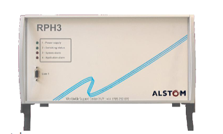
This manual is the service manual for the RPH3 “Point on Wave (PoW)” controller, which is used to guide the synchronous switching operation of high-voltage switchgear and support equipment understanding, installation, use, and maintenance.
Copyright belongs to GE Grid Solutions. The content is informative and can be adjusted according to technical and commercial needs. Unauthorized reproduction and disclosure are prohibited.
Reference architecture
GE internal documents: such as D1621EN (User Manual), D1622EN (RPH Manager Software Manual), etc.
International standard: Following IEC 62271-302 (Non synchronous pole operation of high-voltage switchgear).
Industry Report: Cited from CIGR É 262-264 publication (HVAC Switchgear Control Switching Guide).
Safety and Operation Instructions
Static Electricity and Electrical Safety
Electrostatic discharge (ESD) may damage equipment and should comply with anti-static standards such as EN 61340-5-1.
Power off before operation, confirm that the power supply voltage is compatible (AC 100-240V or DC 48-353V), only qualified engineers can operate.
Storage and installation requirements
Store in a dust-free and dry environment at -40 ℃~+70 ℃, with moisture-proof bags retained; Installed in the control room or relay room, ensuring good grounding, away from vibration sources, supporting 19 inch rack or wall mounted installation.
Principle of PoW Switching Technology
Random switching vs synchronous switching
Random switching: When the coils are powered on simultaneously, it is easy to generate surge current and overvoltage, which can cause equipment aging or protection misoperation.
PoW switching: By delaying the control of coil energization time, the high-voltage contacts are made to contact at the target point of the voltage waveform (such as zero crossing or peak), reducing transient phenomena. For example:
Inductive load (transformer) closing selects peak voltage to reduce excitation inrush current;
Capacitive load (capacitor) closing selects voltage zero crossing to reduce charging current surge.
Key parameters and terminology
Pre arming Time: The current conduction time before the mechanical contact of the contacts during closing, influenced by the dielectric strength decay rate (RDDS).
Operating Time: The time it takes for the coil to be powered on until the contacts fully move, and it is necessary to compensate for the effects of environmental temperature, hydraulic pressure, and other factors.
Adaptive Control: Based on historical operational data, adjust control timing and compensate for unpredictable factors such as equipment aging.
RPH3 Hardware and Functional Architecture
Module composition
M1: Power module, providing internal DC power supply.
M2: Central processing and communication module, integrated with DSP and Linux system, supporting Ethernet and fiber optic communication.
M3: Analog acquisition module, sampling reference voltage, current, temperature, hydraulic pressure and other signals.
M4: Signal and coil drive module, processing switch commands and relay outputs.
M5: Front panel management module, controls LED indicator lights and serial communication.
Core functional modules
Reference voltage sampling: Obtain the grid voltage through VT as a timing reference, supporting L1/L2/L3 phase selection.
Neutral point mode detection: supports hardware jumpers (M4-J5) or software settings to distinguish between grounded, isolated, or unknown modes.
Coil driver: Supports common mode/differential mode wiring, outputs 80ms adjustable pulses, and drives the opening and closing coils of switch devices.
Operation time measurement: Detect contact action through auxiliary contacts or current transformers (CT) with an accuracy of ± 0.1ms.
Compensation mechanism and adaptive control
Compensation factors for operation time
Environmental temperature: Low temperature will prolong operation time. Real time compensation can be achieved through a temperature sensor (4-20mA input), and the compensation meter can be configured through Web MMI.
Control voltage: Voltage fluctuations affect the rate of rise of coil current. The compensation value is calculated using the formula Δ t voltage=(U meas U rate − 1) ⋅ kU ⋅ t OP_rated, where kU is the compensation coefficient (to be measured).
Hydraulic pressure: For hydraulic drive mechanisms, real-time sampling is carried out through pressure sensors, and compensation is made according to Δ t pressure=(P meas P rate − 1) ⋅ kP ⋅ t OP_rated.
Idle time: Devices that have not been operated for a long time will slow down, compensated by the exponential function Δ t idle=A ⋅ (1 − e − BT idle), where A and B are empirical parameters.
Adaptive control is based on historical operational data and utilizes Δt adapt=K⋅(t measured −t commissioning −Δt compensations)+(1−K)⋅Δt adapt_prev Adjust the prediction time series, with K as the weight factor (default 0.3).
Alarm and Data Management
Alarm Type
System alarm: such as abnormal power supply, hardware failure, calibration failure, etc., triggering the red LED “3” on the front panel.
Application alarm: If the reference voltage exceeds the limit, the operation time is abnormal, the compensation value exceeds the limit, etc., the LED “4” will be triggered.
Relay output: 5 relays (1 monostable+4 bistable), which can be configured with alarm correlation logic through Web MMI.
Data recording and communication
Real time data: View parameters such as voltage, current, temperature, etc. through Web MMI, with a refresh rate of 3 seconds or 20 seconds.
Switching record: Stores the last 1025 operation data (“*. arch” file), supports downloading waveforms and event logs through RPH Manager software.
Network interface: Supports IP network (default IP 192.168.5.2), compatible with IEC 61850-9-2 communication protocol.
Application scenarios and switching strategies
Typical load switching scheme
Transformer/Three core Reactor:
Closing: Select the peak voltage (90 ° electrical angle) for the grounding neutral point, and select 0 ° or 180 ° for the isolation neutral point.
Trip: Select the current zero crossing point (corresponding to the peak voltage) to reduce overvoltage.
Single core reactor: The closing target point is the same as the transformer, and the tripping strategy is consistent.
capacitor:
Closing: Select voltage zero crossing (0 °) for the grounding neutral point and phase voltage zero crossing for the isolation neutral point.
Trip: Select the zero crossing point of the current to avoid heavy impact.
Transmission line:
Inductive VT: select voltage zero crossing for closing;
Capacitive VT: It is necessary to evaluate the residual charge in the circuit and select the peak voltage for closing.
Inductive load with NGR: Select the neutral point mode based on the inductance ratio r=LL N, and use a custom switching program when r ≥ 0.3.
Switch program configuration
Built in preset programs (transformers, reactors, capacitors), supporting user-defined modes (User Mode), can adjust the angle offset of each phase.
Environmental adaptability: Operating temperature -25 ℃~+50 ℃, storage temperature -40 ℃~+70 ℃, compliant with RoHS and EMC standards (such as IEC 61000-4-2/3/5).
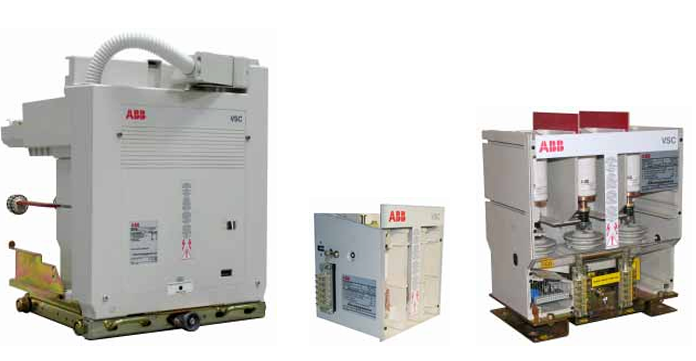
The medium voltage V-Contact VSC contactors are apparatus suitable for operating in alternating current and are normally used to control users requiring a high number of hourly operations.
The V-Contact VSC contactor introduces the drive with permanent magnets, already widely used,experimented and appreciated in medium voltage circuit-breakers, into the worldwide panorama of medium voltage contactors.
The experience acquired by ABB in the field of medium voltage circuit-breakers fitted with drives with “MABS” permanent magnets, has made it possible to develop an optimised version of the actuator (bistable MAC drive) for medium voltage contactors.
The drive with permanent magnets is activated by means of an electronic multi-voltage feeder. The feeders differ according to the integrated functions and to the auxiliary power supply voltage.
Three bands of power supply are available with which all the voltage values required by the major international Standards can be covered.
Each feeder is able to take any voltage value within its own operating band.
All the contactors mentioned above are available,on request, in one of the two following versions.
SCO(Single Command Operated): closing takes place by supplying auxiliary power to the special input of the multi-voltage feeder. On the other hand, opening takes place when the auxiliary power is either voluntarily cut off (by means of a command) or involuntarily (for lack of auxiliary
power in the installation).
DCO (Double Command Operated): closing takes place by supplying the input of the closing command of the apparatus in an impulsive way.
On the other hand, opening takes place when the input of the opening command of the contactor is supplied in an impulsive way.
Fields of application
The V-Contact VSC contactors are suitable for controlling electrical apparatus in industry, in the service sector, in the marine sector, etc.
Thanks to the breaking technique with vacuum interrupters, they can operate in particularly difficult environments.
They are suitable for control and protection of motors, transformers, power factor correction banks, switching systems, etc. Fitted with suitable fuses, they can be used in circuits with fault levels up to 1000 MVA (VSC7 – VSC12)
Compliance with Standards
V-Contact VSC contactors comply with the Stand ards of the major industrialised countries and in particular with the EC 60470 (2000) Standards.
Approvals
Approval by the DNV, RINA and LL.RR shipping registers is foreseen.
• Suitable for installation in prefabricated substations and switchgear both of the card (slim line) and traditional type
• High number of operations
• Direct checking of contact wear
• Long electrical and mechanical life
• Remote control
• Multi-voltage feeder
• Bistable drive of the type with permanent magnets
• Behaviour on power cut adjustable by the customer (instantaneous or delayed opening) in the SCO versions and, should the undervolt age accessory be required, DCO.
Interruption principle
IThe main contacts operate inside the vacuum interrupters (the level of vacuum is extremely high: 13 x 10-5Pa).
On opening, there is rapid separation of the fixed and moving contacts in each contactor interrupter.
Overheating of the contacts, gener ated at the moment they separate,causes formation of metallic vapours which allow the electric arc to be sustained up to the first passage through zero current.
On passage of zero current, cooling of the metallic vapours allows recovery of high dielectric resist ance able to withstand high values of the return voltage.
For motor switching, the value of the chopped current is less than 0.5 A with extremely limited overvoltages.
“MAC” magnetic drive
ABB has implemented this technology in the field of contactors on the basis of experience gained in the field of circuit-breakers with magnetic drive.
The magnetic drive adapts perfectly to this type of apparatus thanks to its precise and linear travel.
The drive, which is of bistable type, is fitted with an opening and a closing coil.
The two coils – individually energised – allow the drive mobile armature to be moved from one of the two stable positions to the other.
The drive shaft is solid with the mobile armature and held in position in a field generated by two permanent magnets (fig. A).
Energising the coil opposite to the magnetic latching position (fig. A) of the core, the magnetic field is generated (fig. B), which attracts and moves the mobile armature into the opposite position (fig. C).
Every opening and closing operation creates a magnetic field concordant with the one generated by the permanent magnets, with the advantage of keeping the intensity of the field itself constant during service, regardless of the number of opera tions carried out.
The energy needed for operation is not supplied directly by the auxiliary power supply, but is always “stored” in the capacitor which acts as an energy accumulator, and therefore operation always takes place with constant speeds and times, independ ently of the divergence of the power supply voltage from the rated value.
The auxiliary power supply has the only aim of keeping the capacitor charged.Consumption is therefore minimal.
The power required is less than 5 W. In order to re-instate the rated power value in the capacitor after an opera tion, there is an inrush of 15 W for a duration of a few tens of milliseconds.
For the reasons indicated above, both for the DCO and for the SCO version it is necessary to supply the auxiliary circuits which recharge the capacitor with a continuous auxiliary power supply of 5W (this value can reach 15W for a few milliseconds immediately following each operation).
Careful selection of the components and a precise design make the electronic multi-voltage feeder extremely reliable, unaffected by electromagnetic interference generated by the surrounding environ ment and free of any emissions which may affect other apparatus placed in the vicinity.
These characteristics have made it possible for the V-Contact VSC contactors to pass the electromag netic compatibility tests (EMC) and obtain the CE mark.
Interfacing shafts
These can be used to interface the apparatus with the kinematics of the switchgear to make interlocks and/or signals.
The interfacing shafts are available in two different lengths (A = 22 mm and 70 mm) and can be mounted on one or both sides of the contactor (as indicated in the following table)
Operation counter
Mechanical operation counter for fixed versions, electric operation counter for withdrawable versions.
This is a device which counts the contactor closing cycles 3 Undervoltage function (only available for DCO)
First of its type, the V-Contact VSC contactor is fitted with an undervoltage function with selectable delays of 0; 0,5; 1; 2; 3; 4; 5 s.
This accessory must be specified at the time of order because it cannot be mounted at a later stage.
Extended connections (terminals)
These allow the centre distance between terminals to be taken from 65 mm to 92 mm.
This accessory must be specified at the time of order because it cannot be mounted at a later stage.
Adapter for application of fuses
The kit includes all the accessories needed to adapt and mount three fuses(according to DIN Standards with dimension e less than 442 mm; according to BS Standards with dimension L less than 553 mm).
The kit can be installed directly onto the fuseholder supports.
The fuses must have dimensions and striker of average type according to DIN 43625 and BS 2692 (1975) Standards.
The electrical characteristics must conform to the IEC 282-1 (1974) Standards.
To select the fuses, see “Conditions of use according to the load” – chapter 3.
The adaptation kits are available in the following types:
3A For fuses according to DIN Standards with distance e = 192 mm
3B For fuses according to DIN Standards with distance e = 292 mm
3C For fuses according to BS Standards (2 x 8 x L = 235 mm)
3D For fuses according to BS Standards (4 x 10 x L = 305 mm)
3E For fuses according to BS Standards (4 x 10 x L = 410 mm)
3F For fuses according to BS Standards with distance L = 454 mm.
Connections alternative to the fuses
The kit includes three flat copper busbars and fixing screws to be installed when the fuses are not needed.
The kit can be installed directly onto the fuseholder supports
Position contacts for connected/isolated position in the truck
These signal the position of the truck in the enclosure/PowerCube module.
The kit includes a set of 10 auxiliary contacts.
This accessory must always be requested for contacts to be used in UniGear type ZS1 switchgear if the same application is not already present on the fixed part.
Isolation lock
Isolation lock for UniGear type ZS1 switchgear and PowerCube modules.
It prevents the apparatus from being racked-in if the unit door is open.
This lock only works if the door of the switchgear/enclosure is also fitted with the corresponding lock.
Locking magnet in the truck
This only allows the withdrawable contactor to be racket into/out of the enclo sure with the electromagnet energised and the contactor open
The table below shows the power supply voltages available.
10Lock for different rated currents (only withdrawable versions)
This prevents insertion of the plug-socket and therefore apparatus closing, in a panel provided for a circuit-breaker.
This lock, which is compulsory for UniGear switchgear, requires the same lock provided on the enclosure / switchgear
Origin: Sweden. As a well-known brand, ABB strictly controls its product technology and quality. This current sensor inherits ABB’s high-quality genes.
Certification status: With CO.CQ certification, this indicates that the product meets specific standard requirements in terms of safety, reliability, and other aspects, providing assurance for user use.
Packaging details: Using brand new original and factory sealed packaging, it can effectively prevent the product from being damaged or affected by moisture during transportation and storage, ensuring that the product received by the user is in the best condition.
Product size and weight:
Net height: 50mm
Net length: 230mm
Net width: 165mm
Net weight: 2kg, moderate size and weight, convenient for installation and integration in various devices, and easy to transport and carry.
Product Overview
ABB 3BHE004385R0001 UNS 0884a, V1 is a current sensor designed specifically for precise measurement of high currents, playing a key role in power monitoring in the industrial field. Its rated current measurement range is 2000A, which can adapt to various complex current monitoring scenarios and provide key data support for the stable operation of various systems. From the appearance, the compact design makes it easy to install inside various devices without taking up too much space.
Brand background
ABB Group is a multinational industrial energy production company established in 1988 through the merger of ASEA and BBC, headquartered in Zurich, Switzerland. In its development process, ABB has continuously innovated and broken through, launching many industry influential products, such as the Azipod electric propulsion system launched in 1990 and the digital solution product ABB Ability launched in 2017 ™ Wait. ABB’s business is extensive, covering multiple fields such as electrification, sports, and process automation. It has numerous customers in 165 countries worldwide and has established an excellent brand image with advanced technology and strict quality control. This current sensor is a reflection of ABB’s high-quality and high-performance brand.
Core functions
Accurate current measurement: It can accurately measure a current of 2000A with extremely high measurement accuracy, providing accurate current data for the system and helping engineers accurately judge the operating status of the system. For example, in large power equipment, real-time monitoring of current can ensure stable operation of the equipment within the rated current range.
Signal transmission and conversion: Convert the measured current signal into an electrical signal that is easy to process and transmit, facilitating connection and interaction with other devices such as control systems, monitoring instruments, etc., to achieve remote monitoring and analysis of data.
Working principle
This current sensor operates based on the principle of electromagnetic induction. When the measured current passes through the primary winding of the sensor, an alternating magnetic field is generated in the iron core. Under the action of this alternating magnetic field, the secondary winding will induce an induced electromotive force proportional to the primary current, thereby generating an induced current. By measuring and processing the secondary induced current, the high current value passing through the primary winding can be accurately calculated, achieving precise monitoring of the 2000A current.
Key advantages
High quality guarantee: Originating from Sweden and inheriting ABB’s strict production process and quality control system, the product has high reliability and can operate stably for a long time in harsh environments, reducing losses caused by equipment failures.
Authoritative certification endorsement: Possessing CO.CQ certification proves that it meets specific standards in terms of safety, reliability, and other aspects, allowing users to feel more at ease during use.
Flexible procurement plan: The minimum order quantity is only 1 piece, and there is a daily supply capacity of 10 pieces, which can meet both large-scale project procurement and small-scale testing needs, reducing the procurement threshold.
Convenient installation design: Moderate size (height 50mm, length 230mm, width 165mm) and lightweight (2kg) make it easy to install and integrate in various devices, and also convenient for transportation.
Precautions
Installation environment: It should be installed in a dry and well ventilated environment, avoiding places with high temperature, high humidity, and strong electromagnetic interference, to prevent affecting the measurement accuracy and service life of the sensor.
Wiring specifications: Strictly follow the product manual for wiring operations, ensure that the wiring is firm and correct, and avoid measurement errors or equipment damage caused by wiring errors.
Regular maintenance: Regularly inspect and calibrate sensors to ensure their measurement accuracy remains within the specified range. It is generally recommended to perform professional calibration every certain period of time (such as six months or one year).
Application scenarios
Power monitoring: used in power plants, substations and other power facilities to monitor the current of transmission lines, transformers and other equipment, ensure the safe and stable operation of the power system, timely detect abnormal fluctuations in current, and prevent faults from occurring.
Industrial automation: In automated production lines in the manufacturing industry, the current of equipment such as motors and frequency converters can be monitored. Through the analysis of current data, intelligent control and maintenance of equipment can be achieved, such as determining whether the motor is overloaded based on changes in current, and providing early warning and maintenance.
Municipal engineering: In facilities such as municipal pumping stations and air conditioning refrigeration systems, monitoring current is used to ensure the normal operation of equipment and optimize energy efficiency. For example, in the air conditioning system of large shopping malls, the operating parameters of refrigeration equipment are adjusted by monitoring current to achieve energy-saving operation.
Transportation: In the charging facilities of electric vehicle charging stations, electric buses, and trucks, the charging current is monitored to ensure the safety and stability of the charging process and prevent damage to the battery caused by overcurrent charging.
ABB UAD206A101 is a programmable logic controller (PLC) specifically designed for industrial environments. In the industrial automation system, PLC plays a core control role, and UAD206A101, with its excellent performance, has become a key equipment for achieving efficient and precise control in many industrial scenarios. It is essentially an electronic system that performs numerical operations and can precisely control various complex industrial processes based on preset programs.
Core functional characteristics
Powerful logical operations and sequence control: Equipped with programmable memory internally, it can store instructions for executing logical operations and sequence control. On industrial production lines, it can accurately coordinate the start and stop sequence of various equipment. For example, on automotive parts assembly production lines, according to preset processes, it controls the robotic arm to grasp and assemble parts in sequence, ensuring orderly production and greatly improving production efficiency and product quality.
Flexible timing and counting functions: with precise timing and counting capabilities. In the process of chemical reactions, precise time can be set to control the reaction duration and ensure that the chemical reaction proceeds fully and stably; In the product packaging process, the counting function is used to count the number of packages, achieving automated packaging counting and quality control.
Integration of Analog and Digital Signal Processing: Supports digital or analog input/output, seamlessly connecting various sensors and actuators. In a smart factory, it can collect real-time analog sensor data such as temperature, pressure, flow rate, as well as digital signals such as equipment operation status and switch on/off. After internal processing, it outputs corresponding control signals to achieve comprehensive monitoring and precise control of the production process.
Highly reliable patented fault-tolerant mechanism: adopting patented fault-tolerant operation technology, by configuring two control modules to work together, the system reliability is greatly improved. When one control module fails, another can seamlessly take over the work immediately, ensuring uninterrupted industrial production processes. This is crucial for industries such as petrochemicals and power that require high continuity of production, effectively avoiding huge economic losses caused by equipment failures.
Accurate time synchronization function: supports external time synchronization using optional GPS satellite signals, ensuring time consistency between the system in different regions and devices. In large-scale industrial automation networks, various devices interact and collaborate based on precise and unified time, greatly improving the stability and coordination of system operation. For example, in distributed energy management systems, various power generation, transmission, and consumption equipment can efficiently cooperate based on precise synchronization time.
Convenient online image update: Provides fault-tolerant online image update function (for FCP270), allowing system program updates to be completed without shutting down the industrial production process. This means that without stopping production, system functions can be upgraded and vulnerabilities can be fixed in a timely manner, reducing production losses caused by downtime maintenance and meeting the modern industrial demand for efficient and sustainable production.
Technical specifications and parameters
Electrical parameters
Rated working voltage: Suitable for common industrial power supply standards, such as 24VDC, to ensure stable operation in complex industrial power grid environments.
Working current range: Depending on the actual load, it can stably carry the corresponding working current, ensuring the normal operation of the equipment under various working conditions.
Isolation voltage: With a high isolation voltage, such as 2500Vrms, it effectively isolates electrical interference between different circuits, prevents equipment from being affected by electrical fluctuations, and ensures system safety and reliability.
Application area
Manufacturing industry: In the field of electronic manufacturing, equipment control is used for automated production lines, such as mobile phone assembly production lines, to accurately control the movements of equipment such as surface mount machines and welding robots, achieving efficient and high-quality production of electronic products; In the mechanical processing industry, the operation of machine tools can be controlled, and parameters such as tool motion trajectory and cutting speed can be accurately controlled according to processing technology requirements to ensure the machining accuracy of mechanical components.
Energy industry: In oil and gas extraction, monitoring and controlling various extraction equipment and transmission pipelines, real-time monitoring of pressure, flow rate and other parameters, to ensure the safety of oil and gas production and transportation; In the power system, it is used for substation automation control, grid scheduling, etc., to achieve remote monitoring and intelligent control of power equipment, and to improve the stability and reliability of power supply.
Chemical and pharmaceutical industries: In the chemical production process, controlling chemical reaction conditions such as temperature, pressure, acidity, etc. ensures stable quality of chemical products; In the pharmaceutical industry, strict control is exercised over drug production equipment and processes to meet drug production quality standards and ensure drug safety and effective production.
Municipal and Environmental Protection: In urban sewage treatment plants, control the operation of water pumps, aeration equipment, etc. to achieve automation of sewage treatment; In smart buildings, managing lighting, air conditioning, elevators and other systems to achieve optimized management and intelligent control of building energy, improve the efficiency of urban infrastructure operation and residents’ living comfort.
Only qualified electricians are allowed to perform installation and maintenance. After power failure, wait for 5 minutes for the intermediate circuit capacitor to discharge.
Measure and confirm that the voltage at the input terminals (U1/V1/W1) and DC terminals (UDC+/UDC -) is close to 0V before starting the operation.
Do not operate when the control cable is live to avoid conducting insulation tests on the drive.
Grounding requirements
The drive, motor, and ancillary equipment must be independently grounded, and the specifications of the grounding conductor must comply with safety standards (such as copper conductor ≥ 10 mm ²).
European CE compliant installation requires 360 ° high-frequency grounding to suppress electromagnetic interference.
Mechanical and Electrical Safety
Avoid single person operation during transportation, pay attention to the high temperature risk of the heat sink, and prevent conductive dust from entering the drive.
When handling printed circuit boards, it is necessary to wear a grounding wristband, and the bending radius of fiber optic cables should not be less than 35 mm.
Driver Overview and Compatibility
Product positioning
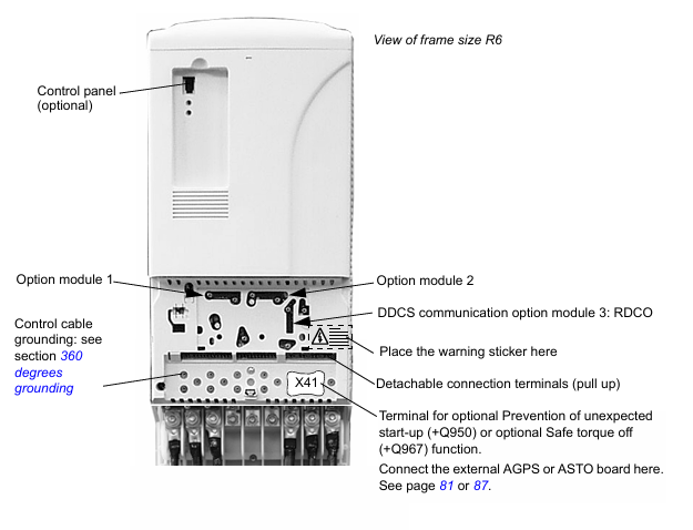
ACS800-04/U4 is an IP20 driver module suitable for industrial automation scenarios, supporting direct torque control (DTC) and compatible with permanent magnet synchronous motors.
Framework classification
Divided by power into R2 to R6 frames, different frames correspond to size, heat dissipation requirements, and installation methods (such as flange installation IP55).
Installation and Debugging
Mechanical Installation
Sufficient heat dissipation space needs to be reserved (such as 200mm space above the R2 frame), and the ventilation design of the cabinet needs to meet the air flow requirements.
During flange installation, IP55 protection must be ensured, and grounding must be connected independently.
electrical installation
Power connection: The input cable should match the rated voltage (208-690 V AC), use a symmetrical shielded cable, and ground the shielding layer 360 °.
Motor connection: Select cable specifications based on the frame (e.g. R2 frame motor cable ≤ 16 mm ²), avoiding the use of power factor compensation capacitors.
Control connection: Analog signals require twisted pair shielded cables, while digital inputs/outputs require attention to logic thresholds (12 V DC is “1”).
Installation of safety features
Prevent accidental startup (+Q950): An external AGPS board is required, powered by 230 V AC, and locked by a switch to prevent accidental startup.
Safe torque shutdown (+Q967): External ASTO board, 24 V DC power supply, in compliance with EN 61800-5-2 standard.
Technical parameters and performance
RATING
Current/power: For example, the R2 frame has a rated current of 5.1 A (230 V AC) and a continuous power of 1.1 kW; the R6 frame has a rated current of 290 A (690 V AC) and a continuous power of 200 kW.
Overload capacity: light load (10% overload) can last for 1 minute/5 minutes, heavy load (50% overload) can last for 1 minute/5 minutes.
Electrical characteristics
Input voltage fluctuation ± 10%, frequency 48-63 Hz, power factor 0.98 (rated load).
Output voltage 0 to input voltage, frequency 0-300 Hz, switching frequency 3 kHz (2 kHz for 690 V units).
Heat dissipation and derating
When the ambient temperature exceeds 40 ° C, the rated current will decrease by 1% for every 1 ° C increase; When the altitude exceeds 1000 meters, the rating will decrease by 1% every 100 meters.
Maintenance and component replacement
Routine maintenance
Clean the heat sink every 6-12 months and check the fan’s operating status annually (with a lifespan of approximately 6 years).
Capacitor replacement cycle: R4 and above frames take about 10 years and need to be reformed according to the manual.
component replacement
When replacing the fan, attention should be paid to model matching (such as the R2 frame fan requiring a flow rate of 35 m ³/h), and the functionality of the capacitor needs to be verified after replacement.
ABB UAD149A0011 3BHE014135R0011 is a powerful controller module that occupies an important position in industrial automation control systems. It is designed specifically for ABB’s AC 800M and AC 800PEC control systems, and can efficiently achieve key tasks such as data exchange, signal processing, and equipment control within the system. It is one of the core components for building a stable and intelligent industrial automation architecture.
Function characteristics
Communication function: As a communication module, it enables the AC 800M system to communicate smoothly with other devices on the Profibus network. Profibus is a widely used fieldbus standard in the industrial field. With excellent communication protocol conversion and data transmission capabilities, UAD149A0011 ensures fast and accurate data exchange between different devices, effectively improving the information flow efficiency of the entire industrial network.
Integrated I/O: This module integrates analog and digital I/O signal processing functions and can support multiple types of input and output signals. Whether it is analog signals from sensors such as temperature and pressure, or digital signals representing equipment status such as switch on/off and motor on/off status, they can be accurately collected and processed by it, and control signals can be output according to the system’s preset logic to achieve precise control of various industrial equipment.
High reliability diagnosis: Built in powerful self diagnostic function that can monitor its own working status in real time. By continuously monitoring hardware circuits, software programs, and data transmission processes, once a fault or abnormality is detected, the module will quickly issue an alarm and generate detailed diagnostic reports to help maintenance personnel quickly locate the problem, greatly reducing system downtime and ensuring the continuity and stability of industrial production.
Fast scanning and response: With fast scanning speed, it can complete the acquisition and processing of input signals in a very short time, and output control instructions in a timely manner. This feature significantly reduces the response delay of the system, enabling industrial automation systems to quickly respond to various changes in the production process, improving production efficiency and product quality.
Technical Parameter
Electrical parameters
Rated input voltage: 24VDC, suitable for common industrial DC power supply systems, ensuring stable power supply.
Isolation voltage: reaches a high standard, such as 2500Vrms, effectively isolates electrical interference between different circuits, ensuring the safety and reliability of the system.
Power consumption: Maintain at a reasonable level, with specific values depending on the actual workload. Lower power consumption helps reduce system operating costs.
Physical parameters
Size: Approximately 145mm x 145mm x 145mm, the compact design allows for flexible installation within limited control cabinet space, saving space resources.
Weight: Moderate weight facilitates installation and maintenance operations. Specific weight values can be found in the product manual.
I/O parameters
Analog input: Supports multiple types of analog input signals, such as 0-10V, 4-20mA, etc., with high resolution and accuracy, capable of accurately collecting analog data.
Analog output: It can output stable analog signals, which are used to control regulating valves, frequency converters and other equipment. The output accuracy is high and can meet the strict requirements of industrial control.
Digital input/output: With multiple digital input/output channels, it can quickly process digital signals, respond quickly, and is suitable for various switch control scenarios.
Application scenarios
Industrial automation production line: In automated production lines such as automobile manufacturing and electronic equipment production, UAD149A0011 can connect various sensors, actuators, and controllers to achieve comprehensive monitoring and precise control of the production process. For example, it can control the movement of the robotic arm based on the position information of the parts fed back by sensors, ensuring accurate grasping and assembly of the parts, and improving the automation level and production efficiency of the production line.
Process control system: In the field of process control in industries such as chemical, power, metallurgy, etc., this module can collect real-time process parameters such as temperature, pressure, flow rate, etc., and output control signals according to preset control strategies to adjust various equipment in the production process, such as valves, pumps, etc., to ensure stable operation of the production process, optimize production processes, improve product quality and production safety.
Intelligent building control system: In intelligent buildings, UAD149A0011 can be used to connect and control lighting systems, air conditioning systems, security systems, etc. By analyzing and processing various sensor data, intelligent adjustment of the building’s interior environment can be achieved, such as automatically adjusting lighting brightness based on indoor light intensity, automatically controlling air conditioning operation based on temperature changes, and improving the intelligence level and energy utilization efficiency of the building.
BSM N series: low inertia, high dynamic response, using neodymium iron boron magnets, peak torque can reach 4 times continuous torque, supports multiple feedback devices (rotary transformers, Hall sensors, incremental/absolute encoders), protection level IP54/55, working temperature -20 ℃ to+70 ℃, with IEC and NEMA configurations.
BSM C series: high inertia, economical and practical, peak torque is 3 times the continuous torque, suitable for applications that require higher inertia matching, and also supports multiple feedback devices and protection configurations.
SSBSM series: made entirely of stainless steel material, designed for food, liquid, sanitary, and corrosive environments, with a protection level of IP67, capable of withstanding 1500 psi flushing, and certified by BISSC, UL, cUL, and CE.
BSM 25&33 series: Durable circular shell design, supporting foot installation, using standard and reliable neodymium magnet design, can take advantage of brushless technology advantages such as low maintenance, quiet operation, fast acceleration, high torque and power output.
Technical Parameter
Electrical parameters: Different series of motors have different rated voltage, current, frequency and other parameters, such as BSM N series rated voltage 220V, rated current 15A, frequency 50/60Hz, isolation voltage 2500Vrms, etc.
Mechanical parameters: including motor size, weight, inertia, speed range, etc. For example, the BSM50N has dimensions of approximately 172mm × 95mm × 142mm, a weight of 2.4lbs/1.1kg, and a maximum rotational speed of 10000rpm.
Performance parameters: continuous stall torque, peak torque, torque constant, voltage constant, thermal resistance, thermal time constant, etc. For example, BSM50N-133 has a continuous stall torque of 3.9lb in (0.45Nm) and a peak torque of 15.9lb in (1.8Nm).
Performance Curve
The document provides current torque speed performance curves for different models of motors in various series, demonstrating the performance of the motors under different working conditions, helping users intuitively understand the operating status of the motors under various working conditions.
Dimensions and installation
IEC mounting: Detailed lists the installation dimensions of each series of motors, including parameters such as P, AB, U, AH, as well as the lengths of different models of motors with and without feedback devices, and the length and weight increase when equipped with brakes.
NEMA mounting: Introduces the relevant dimensional parameters of NEMA mounting, such as the dimensions of BSM50 series NEMA 23, BSM63/80 series NEMA 34/42, etc.
Options
Cooling kit: BSM90/100 and BSM132 series have blower cooling options, and different models of motors correspond to different blower kit numbers, voltages, currents, and air volumes.
Braking: Data on the holding torque, power, voltage, current, action time, and inertia of various series of motor brakes.
Connectors and cables: connector models, descriptions, and numbers for motor power, feedback, and other connections, such as MCSPOW-08, MCSRES-12, etc.
Engineering information
Motor identification matrix: BSM N, C series and BSM25, 33 series motor identification rules, including frame, series, size, winding code, options, etc.
Selection of servo motors: This article introduces the methods for calculating the requirements of servo motors, including determining the friction and inertia of the load, as well as calculating parameters such as speed, torque, inertia, etc. under different mechanical transmission modes (direct drive, gear drive, tangential drive, ball screw drive).
Motion Curve Analysis: How to interpret the speed time curve, calculate acceleration torque, operating torque, deceleration torque, and root mean square torque, and determine the torque demand of the motor throughout the entire working cycle.
Temperature calculation: Calculate the temperature rise of the motor winding based on power loss and thermal resistance, and determine whether the motor is operating within the safe temperature range.
Drivers and controllers
Servo drive: MicroFlex analog、MicroFlex e100、MicroFlex e150、MotiFlex e100、MotiFlex e180 The characteristics, parameters, models, and selection information of the series of drivers.
Motion controllers: The functions, number of axes, communication methods, and order codes of controllers such as NextMove ESB-2, NextMove e100, and NextMove PCI-2.
Software tool
ABB DriveSize and MCSize software tools can be used for the selection of servo motors and drives. MCSize has a motor database and selection criteria to help users easily and accurately choose suitable servo motors and drive systems.
PLC system
This article introduces the system overview, expansion capabilities, and features of the AC500, AC500 eCo, and AC500-XC series PLCs. For example, the AC500 CPU can locally expand up to 10 I/O modules, while the AC500-XC is suitable for extreme environments.