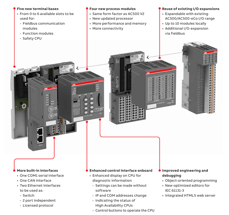
AC500 V3 is the third-generation programmable logic controller launched by ABB. As a technological iteration product of the AC500 series, its core positioning is to bridge industrial automation and the Internet of Things (IoT). This series extends the original AC500 V2 platform with four new CPUs (PM5630/5650/5670/5675), achieving comprehensive upgrades in performance, connectivity, and network security while maintaining hardware compatibility. Its
Architectural features are as follows
Processor and Memory: Adopting a new generation processor, the computing speed has been significantly improved. Taking PM5670-2ETH as an example, the bit operation cycle is only 0.002 μ s, which is 10 times higher than the V2 platform. It is equipped with 160MB program memory and 8GB flash drive (PM5675), supporting complex algorithms and data storage.
Dual Ethernet architecture: Two independent Ethernet interfaces onboard, configurable as switches or independent ports, supporting IEEE 802.3 standard, integrated with web servers and multiple industrial protocol stacks, without the need for additional communication modules.
Core technical characteristics
1. Performance and computational capability
Instruction efficiency: Supports bit/word/floating-point operations, with the floating-point operation cycle shortened from 0.120 μ s in V2 to 0.002 μ s (PM5670), meeting the requirements of high-speed closed-loop control.
Memory allocation: Programs, data, and web memory are independently partitioned, supporting dynamic allocation. It can run up to 200+task instances simultaneously and is suitable for multi axis motion control and complex logical operation scenarios.
2. Industrial communication and protocol support
Fieldbus integration:
Control layer: Built in CANopen master station, Ethernet IP (under development) Modbus TCP/RTU, Supports PROFINET and EtherCAT (requires module expansion).
Management: OPC UA Server supports data access and alarm services, MQTT client connects to cloud platform through TLS encryption to achieve device data cloud (such as ABB Ability) ™ Platform).
Special fields: KNX (Building Automation), BACnet (Intelligent Buildings), IEC 61850 (Substation Communication) and other protocols are activated through license to adapt to cross industry requirements.
Network topology flexibility:
Dual ports can be configured as “redundant ring network” or “three-layer routing”, for example, port 1 connects to the factory intranet (OPC UA), and port 2 connects to the Internet (MQTT), supporting port mirroring and traffic monitoring.
3. Network security design
Firmware protection: Hardware security chips implement firmware digital signatures to prevent malicious tampering; The transmission of engineering files adopts AES encryption and is integrated with ABB Ability ™ Two way certificate authentication is required for Automation Builder.
Communication encryption: HTTPS/FTPS is used for file transfer, OPC UA supports role-based access control (RBAC), MQTT messages are encrypted through TLS 1.2 to block man in the middle attacks.
Special Version: AC500-XC V3 (Extreme Environment Type)
Designed for harsh industrial scenarios, with multiple environmental adaptability certifications:
Climate adaptability:
Temperature: -40 ° C to+70 ° C for continuous operation, meeting the needs of cold storage and metallurgical high-temperature areas.
Humidity: 100% humidity+condensation protection, meets G3 level corrosion standards, suitable for offshore platforms and chemical workshops.
Mechanical reliability:
Vibration: 4g root mean square random vibration (500Hz), 2g sine vibration, tested according to IEC 60068-2-6, suitable for construction machinery.
Altitude: 4000 meters (620hPa pressure), supporting the application of power stations in high-altitude areas.
Simulation and testing: Offline simulation function (under development) can simulate CPU operation, verify program logic without hardware, and shorten debugging cycle.
Version control: Built in Subversion client, supports collaborative development among multiple people, automatically records code change history, and reduces project risks.
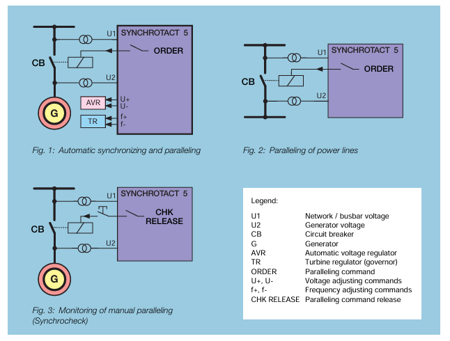
Positioning and Function: SyncHROTACT ® 5 is the fifth generation synchronous equipment produced by ABB Switzerland, used for automatic synchronization of generators and power lines, as well as parallel connection of synchronous lines. It is designed for fully automatic operation of dual channel or single channel systems and can be used as a manual parallel monitoring element or an independent fully automatic synchronization unit to ensure safe and reliable synchronization.
Application scenarios: including automatic synchronization and parallel connection of generators and power lines, automatic parallel connection of synchronous and asynchronous lines and busbars, automatic or manual parallel monitoring (synchronous inspection) of power lines, generators, and voltage free lines (no-load busbars).
Security and usability design
Safety design:
Dual channel system: adopting a compact dual channel system, including two hardware and software independent devices connected in series, the first channel performs automatic synchronization, and the other is independently monitored, designed by different engineers and using different microprocessors to prevent systematic failures.
Manual synchronous monitoring: Manual synchronization is ensured by connecting the monitoring device (synchronous check) in series with the manual parallel switch to ensure safety.
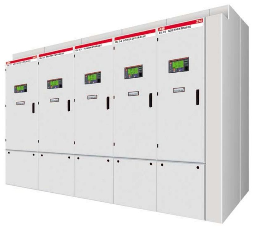
Usability Design: Provides multiple redundant configurations, such as a dual channel main synchronization system with manual parallel switch bypass synchronization system and synchronization check parallel, or two automatic dual channel systems, to achieve the highest safety and maximum availability. The dual channel, automatic channel, and single monitoring channel systems are each housed in one enclosure, while the redundant dual channel system is housed in one enclosure with interconnecting wiring.
Function and Type
Special function: It can store up to seven sets of parameters from different parallel points, with freely configurable digital inputs and outputs. It supports rated frequencies of 50Hz, 60Hz, and 16 2/3Hz and can replace the old SYNC HROTACT system or other manufacturers’ synchronization units.
Reduce engineering costs: The output contacts can carry higher currents, reduce the need for auxiliary relays, isolate all I/O, eliminate the need for a separate power unit, have prefabricated units to choose from, and reduce wiring through a bus control system.
Quick debugging: Use the “SynView” software to recommend parameter values and display ranges. The system includes an intelligent program that can recommend parameters based on generators, circuit breakers, etc., or control debugging through the front panel.
Easy to integrate: It can be easily integrated into modern bus control systems, with communication interfaces supporting MODBUS RTU, Profibus DP, or LON Bus protocols, while maintaining independent protection modules.
Remote maintenance: provide a remote maintenance interface, and communicate with TCP/IP protocol through the Ethernet interface after obtaining the IP address. The PC software “SynView” can directly access the device through the Internet.
Equipment types: including SYN 5100 for simple synchronization check, SYN 5200 for advanced functionality, SYN 5201 for single channel automatic synchronization with frequency and voltage regulation, SYN 5202 for dual channel automatic synchronization system with series synchronization check, SYN 5302 for redundant automatic dual channel synchronization system, and SYN 5500 for auxiliary equipment connecting multiple parallel points.
SynView tool
Function: Used for simple and fast debugging of SYNC HROTACT 5 devices, supports German, English or French, runs on Microsoft Windows 95, 98, 2000 or NT systems, and has four main functions: parameter setting, actual value display, transient recorder function, event and error recording, etc.
Technical Parameter
Power supply and power consumption: The nominal voltage range includes 24/48V DC, 100-125V AC/DC, 220-250V, and the allowable voltage range is DC 0.75-1.25 × Un. The maximum power consumption (SYN 5302) is 25W/35VA.
Measurement input: nominal voltage range 50-130V AC, allowable voltage range 0-1.3 × Un, nominal frequency 16 2/3/50/60Hz.
Digital input and relay: The digital input current consumes DC 6-8mA, the maximum switching voltage of parallel relays is 250V AC/DC, and the maximum switching current is continuously 5A. The maximum switching voltage of adjustment, command, and signal relays is 250V AC/DC, and the maximum switching current is continuously 1.5A.
Measurement range: Voltage 0-1.3 × Un, angle matching from α -179 to+180 degrees, frequency 10-100Hz, slip s0-50%, acceleration ds/dt0-10%/s, parallel time tON0-1s.
Positioning and Function: The SUE 3000 is a high-speed switching device mainly used to automatically switch to a backup power source in case of power interruption or voltage drop to ensure continuous power supply for users, protect auxiliary processes from expensive downtime, and also support manual start-up switching to simplify device operation.
Application scenarios: Suitable for occasions sensitive to power outages, such as auxiliary facilities in power plants (steam, gas turbines, combined cycles, nuclear power plants), environmental protection technology facilities (flue gas purification, waste incineration), continuous industrial processes (chemical plants, highly automated industrial facilities, fiber manufacturing, petrochemical processes), etc.
Switchgear configuration
Dual circuit breaker configuration (variant 1): commonly used in auxiliary facilities of thermal power plants. Under normal circumstances, one of the two power sources is supplied by the busbar, and the other is disconnected. It is not allowed for both to supply power simultaneously. In case of a fault, it switches to the second power source. The device is designed symmetrically and can be started and switched from either side.
Two line, one bus configuration (variants 2 and 4): The load is divided into two sections of busbars due to redundancy, and the contact circuit breaker is usually disconnected. Both lines are running. When one line fails, it switches from the fault line circuit breaker to the contact circuit breaker, and can be manually switched back after the fault line is restored.
Three line two option configuration (variant 3): Used for situations where three lines are needed and two options are available, only switching between the pre selected two lines, with fixed input signal connections, and pre selection logic can be combined with additional logic conditions.
Triple line selection configuration (variant 5): When the triple line is available, switching operations can be performed between any two lines. The input signal is hard wired, and the selection logic can be associated with other logic conditions.
Core functions
Working mode: Equipped with fast processing logic and high-precision analog signal processing, it permanently compares the bus voltage with the backup power supply voltage, generates synchronization standards such as phase angle, frequency difference, backup power supply voltage, and bus voltage, ensuring the shortest switching time during startup and reducing transient effects on users.
Permanent determination of network conditions: synchronous standard online calculation, with a determined switching mode at startup, can be started immediately to increase the probability of rapid switching, and the device is only ready when the two circuit breakers are in different states and in their working positions.
Switch Mode
Quick switching: Both the main power supply and the backup power supply are executed within the specified limits during startup, with two types of control: simultaneous control and sequential control. The no current switching time controlled simultaneously depends on the time difference between circuit breaker operation. Sequential control requires waiting for the disconnection indication of the incoming circuit breaker before issuing the command to close the backup circuit breaker.
First phase coincidence switching: When there is no synchronization condition during startup, disconnect the original incoming line first, determine the first phase coincidence point and the time when the closing command is issued through predictive calculation, and connect the backup power supply when the voltage difference is minimized. Careful engineering design and debugging are required.
Residual voltage switching: Used when the first phase coincidence switching is not feasible. When the bus voltage drops to the preset allowable value, connect the backup power supply without evaluating the angle or frequency difference. Transient effects are controllable.
Timed switching: Quick switching is executed when it is not completed within the preset time, which belongs to the safe stage and generally does not occur under normal operating parameters.
Special support functions: including decoupling (automatically reversing to avoid illegal network coupling when mechanical faults are detected), circuit breaker tripping switching (monitoring the position of the circuit breaker and performing switching when disconnected for no reason), and non independent network switching mode (using a programmed time frame to determine if the backup power source is ready).
Configuration and Parameters
Configuration method: LED indicators, single line diagrams, control schemes, automation sequences, etc. are configured through software functional modules. FUPLA programming language is used to provide multiple logic functional modules, and parameters can be modified through HMI control units or connected to configuration computers.
Variable functional parameters: including frequency difference for quick switching, network angle, bus voltage value, backup power supply voltage value, maximum frequency gradient for initial phase coincidence switching, bus residual voltage value for residual voltage switching, original power undervoltage value and delay time for undervoltage startup, timed closing command time, circuit breaker command delay time, etc.
Fault recording: Equipped with a fault recording module, it can record analog and binary data. The analog signal sampling rate is 1.2kHz, and the recording time includes pre trigger and post trigger times. It is stored in a circular buffer and can be exported for analysis.
Operation interface
LCD display: Backlit LCD display, with a single line diagram on the left and measurement values, menus, protection signals, and event records on the right. It can display up to eight switch device icons and other motor, transformer, and other icons.
Status indication: including operating status (green LED “Ready”), communication status (green LED, turns red in case of fault), alarm indication (red LED), interlock status (unused).
REF542plus is a new generation of intelligent electronic device (IED) for medium voltage distribution systems launched by ABB, designed specifically for scenarios such as gas insulated switchgear (GIS) and air insulated switchgear (AIS), integrating protection, measurement, control, monitoring, and power quality analysis functions. Its core architecture adopts a three processor separation design:
DSP (Digital Signal Processor): Independently executes protection algorithms and high-precision measurements to ensure that fault response is not affected by control tasks.
MC (microcontroller): handles switch control, logic interlocking, and automation sequences, supporting FUPLA graphical programming.
CP (Communication Processor): Supports protocols such as IEC 61850, Modbus, DNP3, etc., to achieve high-speed data exchange with substation automation systems.
Hardware is divided into central unit and HMI control unit:
Central unit: including power module, I/O interface (analog/binary) and optional communication board, supporting standard chassis (2I/O board+1 communication board) or wide chassis (3I/O board+1 analog output board).
HMI control unit: independently installed on the switchgear door panel, equipped with backlit LCD, 8 operation buttons, 3 sets of LED light columns, and electronic key interface, supporting RS485 communication with the central unit.
Core Function Analysis
1. Protection function system
REF542plus supports over 20 protection algorithms, covering all fault types in the entire distribution network scenario:
Ground fault protection: Directional grounding (67N) is based on the Io UO phase criterion, while non directional grounding (51N) supports admittance type protection (Yo criterion), suitable for ungrounded/resonant grounding systems, with a sensitivity of 0.01mS.
Voltage and frequency protection: three-phase overvoltage/undervoltage (59/27), residual overvoltage (59N), frequency anomaly (81), supports df/dt change rate monitoring to prevent system oscillation.
Equipment specific protection: Transformer differential (87), motor stalling (51LR), thermal overload (49), supporting thermal memory function and environmental temperature compensation.
Arc protection: 3-channel optical sensor input, combined with current criterion, can quickly trip within 9ms, reducing the risk of damage caused by switchgear faults.
2. Measurement and monitoring capabilities
Direct measurement: 8-channel analog input (3 sets of current/voltage), supporting traditional CT/PT or Roche coil/resistive voltage divider sensors, with accuracy up to Class 1 (measurement)/Class 3 (protection).
Calculation parameters: line voltage, positive and negative sequence components, active/reactive power, power factor, electrical energy, supporting maximum demand recording and historical data storage.
Equipment status monitoring: mechanical life counting of circuit breakers, spring energy storage status, SF6 gas pressure monitoring, assisted by event recording (30 recent events) and fault waveform recording (5 x 5s, 1.2kHz sampling) for fault analysis.
3. Control and Automation
Local/remote control: Circuit breaker opening and closing can be achieved through HMI buttons or station control system, supporting electronic key permission management (protection parameter setting/control mode switching).
Interlocking and Automation Sequence: Based on FUPLA programming, cross interval interlocking (such as interlocking between bus tie switch and incoming switch), automatic reclosing (three-phase primary/secondary reclosing), and synchronous inspection (25) are implemented to meet the requirements of power grid interconnection.
Technical parameters and interface characteristics
Positioning and Function: REF615 is an intelligent electronic device (IED) designed specifically for public substations and industrial power system feeders, used for the protection, control, measurement, and monitoring of radial, ring, and mesh distribution networks (including distributed generation). It is a Relion ® The members of the 615 protection and control series products adopt compact and withdrawable unit designs, fully leveraging the potential of the IEC 61850 standard for communication and interoperability between substation automation equipment.
Core Capability: Provides primary protection for overhead lines and cable feeders, and can also serve as backup protection for independent redundant protection systems. Based on selected standard configurations, it is suitable for protecting overhead lines and cable feeders in isolated neutral points, resistance grounding, compensation, and solid-state grounding networks. After configuring specific parameters, it can be directly put into use and supports multiple communication protocols.
Standard configuration
Configuration type: REF615 has 8 standard configurations, and different configurations have different combinations of protection functions. For example, A and B configurations include non directional overcurrent and directional ground fault protection, while C and D configurations include non directional overcurrent and non directional ground fault protection.
Function support: The standard signal configuration can be changed through the graphical signal matrix or optional graphical application function of PCM600. Its application configuration function supports the use of various logic elements (including timers and triggers) to create multi-layer logic functions, combining protection functions with logic function blocks to adapt IED configuration to user specific application needs.
Protection function
Main protection function: Provides directional and non directional overcurrent, thermal overload protection, as well as directional and non directional ground fault protection. According to standard configuration, admittance type ground fault protection can replace directional ground fault protection, and also has sensitive ground fault, phase to phase open circuit, transient/intermittent ground fault, overvoltage and undervoltage, residual overvoltage, positive sequence undervoltage, and negative sequence overvoltage protection functions.
Additional protection function: The standard configuration H of the IED provides frequency protection (including over frequency, under frequency, and frequency change rate protection), enhanced by optional hardware and software, with three optical detection channels for metal enclosed indoor switchgear circuit breakers, busbars, and cable room arc fault protection. The arc fault protection sensor interface is on the optional communication module.
Application scenarios
Network type: Can be equipped with directional or non directional grounding fault protection. Directional grounding fault protection is mainly used for isolated neutral points or compensating networks, while non directional grounding fault protection is suitable for direct or low impedance grounded neutral point networks, and can be used for ring and mesh distribution networks as well as radial networks containing distributed generation.
Specific applications: Different standard configurations are suitable for different scenarios, such as standard configuration G containing one conventional residual current input and three sensor inputs, suitable for compact medium voltage switchgear with limited space, and standard configuration H suitable for industrial power systems, etc.
Supported ABB solutions
System integration: The 615 series of protection and control IEDs and COM600 station automation equipment form a true IEC 61850 solution for reliable power distribution in public and industrial power systems. Through the provided connection package, IEDs can be easily configured and integrated with COM600 or MicroSCADA Pro network control and management systems through the PCM600 protection and control IED manager.
Communication and Functionality: The 615 series IEDs natively support the IEC 61850 standard, including binary and analog level GOOSE message passing. The COM600 provides enhanced substation level functionality using interval level IEDs for data content, with a web-based HMI and gateway functionality, providing seamless connectivity between substation IEDs and network level control and management systems.
Control function
Circuit breaker control: The IED provides control over a circuit breaker, equipped with dedicated buttons for opening and closing the circuit breaker. The optional large graphic LCD includes a single line diagram (SLD) indicating the position of the circuit breaker, and the interlocking scheme required for the application is configured through the signal matrix or application configuration function of PCM600.
Synchronization check: According to the standard configuration, the IED also includes a synchronization check function to ensure that the voltage, phase angle, and frequency on both sides of the disconnected circuit breaker meet the conditions for secure interconnection between the two networks.
Measurement and recording function
Measurement parameters: Continuously measure phase current, current symmetry component, and residual current. If voltage measurement is included, residual voltage, phase voltage, and voltage sequence component are also measured. According to the standard configuration, frequency measurement is also provided to calculate the current demand value within the user’s selectable preset time frame, thermal overload of the protected object, and phase imbalance value based on the ratio of negative and positive sequence currents. Three phase power and energy measurement, including power factor, are provided.
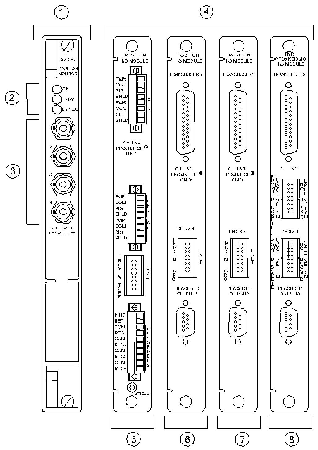
The 3500/45 position monitor is a 4-channel precision monitoring device developed by Bently Nevada, specifically designed for monitoring position related parameters of rotating machinery. Its core function is to receive signals from proximity sensors (Proximitors), rotary position sensors (RPTs), AC/DC linear variable differential transformers (AC/DC LVDTs), and rotary potentiometers. Through signal conditioning and comparison with user programmable alarm thresholds, it achieves mechanical protection and status monitoring.
Core competencies:
Multi parameter monitoring: supports 8 measurement functions including axial (thrust) position, differential expansion, casing expansion, valve position, etc. Channels are programmed in pairs (such as channels 1-2 and 3-4 can perform different functions separately, but casing expansion only supports channels 3-4).
Flexible configuration: Customize the full-scale range, filtering parameters, and alarm thresholds through the 3500 configuration software to adapt to different mechanical operating conditions.
Redundancy design: Supports TMR (Triple Modular Redundancy) configuration, improves system reliability through a 2 out of 3 voting mechanism, and is suitable for monitoring critical equipment.
Application scenarios:
Used for monitoring parameters such as axial displacement of rotors, thermal expansion difference between shafts and casings, valve opening, etc. in large rotating machinery such as steam turbines and compressors, to prevent equipment failures such as rubbing and overload caused by abnormal positions.
Detailed explanation of technical specifications
1. Input characteristics
Signal type: Supports sensor inputs such as Proximitor (e.g. 3300XL series), DC LVDT (25-508 mm range), AC LVDT (25-254 mm range), rotary potentiometer (50 ° -300 ° rotation range), etc.
Impedance and power consumption:
The input impedance of DC LVDT is 1M Ω, the Proximitor/RPT is 10K Ω, and the rotary potentiometer is 200K Ω.
The power consumption varies depending on the I/O module: typically 7.7W when using position I/O modules, 8.5W for AC LVDT modules, and 5.6W for rotary potentiometer modules.
2. Sensitivity and accuracy
Thrust position: Sensitivity 3.937 mV/mm (100 mV/mil) or 7.874 mV/mm (200 mV/mil), accuracy ± 0.33% of full scale (typical), maximum ± 1%.
Differential expansion:
Standard single slope: Sensitivity 0.394-7.874 V/mm (10-200 mV/mil), accuracy varies depending on the slope angle and range, with a maximum error of ± 2% (such as when the full-scale span is less than 3 Vdc).
Shell expansion: DC LVDT sensitivity is 0.05-0.20 V/mm (1.25-5.00 V/in), AC LVDT is 9.45-28.74 mV/V/mm (0.24-0.73 mV/V/mil).
Valve position: The sensitivity of the rotary potentiometer is 41 mV/degree, the RPT is 50-140 mV/degree, and the AC LVDT is 3.94-28.74 mV/V/mm.
3. Output characteristics
LED indication:
OK light: It lights up when the module is running normally.
TX/RX light: Flashes when communicating with other modules in the rack.
Bypass light: It lights up when the channel is bypassed.
Analog output:
The recorder outputs 4-20 mA, proportional to the full range (such as 20 mA for a full range of 10 mm), with a load resistance of 0-600 Ω, a resolution of 0.3662 μ A/bit, and a temperature drift of ± 0.7%.
Buffer sensor output: 1 coaxial interface per channel, short circuit protection, DC LVDT channel 3-4 offset -10 Vdc, AC LVDT output is the DC characteristic value of the AC signal.
4. Signal conditioning and filtering
Frequency response:
Thrust/differential expansion: Direct filter -3 dB at 1.2 Hz, gap filter -3 dB at 0.41 Hz.
Shell expansion/valve position: Position filter -3 dB at 0.41 Hz, suitable for low-frequency mechanical displacement monitoring.
Alarm mechanism:
The Alert threshold can be set to 0-100% full scale, and the Danger threshold supports any two proportional value configurations, with a time delay of 1-60 seconds (Alert) or 0.1 seconds (Danger), and an alarm accuracy of ± 0.13% of the target value.
Configuration plan and I/O module
1. I/O module types and adaptation scenarios
Module model and function applicable to sensors
01 Internal terminal module directly connects to Proximitors, RPTs, DC LVDTs, suitable for non hazardous areas such as 3300XL series, 25 mm Extended Range, etc
02 External terminal module is connected to external terminal blocks through cables, simplifying rack wiring as above
03 Discrete TMR External Module Triple Redundancy Configuration, with independent sensors for each channel, enhances reliability Proximitor/DC LVDT
05 AC LVDT internal module is dedicated to AC LVDT signal conditioning, supporting a range of 25-254 mm AC LVDT 25 mm/50 mm, etc
The internal module of the 07 rotary potentiometer is compatible with rotary potentiometers (50 ° -300 °) for valve opening monitoring
2. Key points of TMR configuration
Discrete and bus modes:
Discrete mode (module 03): Three independent sensors are connected to three modules respectively, suitable for critical measurements (such as thrust position).
Bus mode (module 04): Single sensor signals are distributed to three modules through the bus, which has lower cost but slightly lower reliability.
Voting mechanism: When the deviation between the output of a module and other modules exceeds the set threshold (such as 5%), an event log is triggered to ensure data consistency.
3. Typical configuration examples
Turbine thrust monitoring:
Sensor: 3300XL 8mm Proximitor with a sensitivity of 200 mV/mil.
Channel configuration: 1-2 channels are set as thrust positions, with a full range of 25-0-25 mil, an Alert threshold of 15 mil, a Danger threshold of 20 mil, and a filtering frequency of 1.2 Hz.
Boiler pipeline expansion monitoring:
Sensor: 50 mm DC LVDT, sensitivity 0.10 V/mm (2.50 V/in).
Channel configuration: 3-4 channels are set for chassis expansion, with a full range of 0-50 mm and an alarm delay of 2 seconds, adapted to the slow change characteristics of thermal expansion.
Ordering and installation information
1. Component numbering rules
3500/45-AXX-BXX:
AXX: I/O module type (e.g. 01=internal terminal, 05=AC LVDT).
BXX: Authentication options (01=CSA/NRTL/C Class I, Div 2).
Example: 3500/45-01-01 represents an internal terminal module with CSA certification.
2. External components and spare parts
Terminal block:
Proximitor/DC LVDT: 125808-06 (Euro interface) or 128015-06 (terminal block).
AC LVDT: 141208-01 (Euro interface), supports signal conditioning and isolation.
Consumables: 00530843 (I/O module four pin splitter), used for sensor type matching.
3. Installation requirements
Space occupancy: The monitor occupies one full height front slot, and the I/O module occupies one full height rear slot, which needs to be used in conjunction with a 3500 rack.
Environmental compatibility:
Working temperature -30 ° C~65 ° C, storage -40 ° C~85 ° C, humidity ≤ 95% non condensing, in compliance with EN 61000-6-4 electromagnetic compatibility standard.
Explosion proof certification: Equipped with CSA certification module, suitable for Class I, Div 2 Groups A-D hazardous areas, meeting the needs of petroleum, chemical and other scenarios.
Application precautions
Sensor matching:
Differential expansion requires the use of an Extended Range Proximitor (e.g. 25 mm) to ensure that the range covers the expansion difference between the shaft and the casing.
It is recommended to use DC LVDT for casing expansion to avoid AC LVDT phase drift affecting accuracy.
Software version requirements:
TMR configuration requires 3500 configuration software 2.41 or above, and when using RPT for valve position, software 3.00 or above is required.
Maintenance suggestion:
Regularly verify the alarm function (such as triggering Alert/Ranger with input analog signals), and check the consistency between the LED status and the recorder output.
When hot plugging modules, power should be turned off to avoid static electricity damaging the circuit board (it is recommended to wear an anti-static wrist strap).
Summary
The 3500/45 position monitor provides accurate position parameter monitoring for rotating machinery through multi-channel and high-sensitivity design. Its modular configuration and TMR redundancy mechanism ensure system reliability, making it suitable for key fields such as power, petrochemicals, and metallurgy. Users can choose the appropriate combination of I/O modules and sensors based on the type of machinery and monitoring requirements, and achieve customized protection solutions through flexible software configuration, providing data support for the safe operation of equipment.
3500/42 Proximitor ®/ The earthquake monitoring module is a four channel monitoring device that can receive input signals from a proximity probe and seismic sensors, and achieve monitoring functions such as radial vibration, thrust position, eccentricity, differential expansion, acceleration, and velocity through configuration. Its core function is to drive alarm output by comparing the current machine vibration value with the preset alarm threshold, and provide machine status data for operation and maintenance personnel.
Key Features
TMR architecture: Supports triple modular redundancy (TMR) configuration, avoids single point of failure through a 2 out of 3 voting mechanism, and ensures system reliability.
Flexible configuration: Customize channel types, alarm thresholds, filtering parameters, etc. through 3500 rack configuration software to adapt to different monitoring scenarios.
Real time diagnosis: Built in self checking function, quickly locate faults through LED indicator lights and event logs.
Safety certification: Compliant with standards such as IEC 61508, suitable for hazardous areas (such as Class I, Division 1/2).
Product Architecture and Working Principle
Hardware Architecture
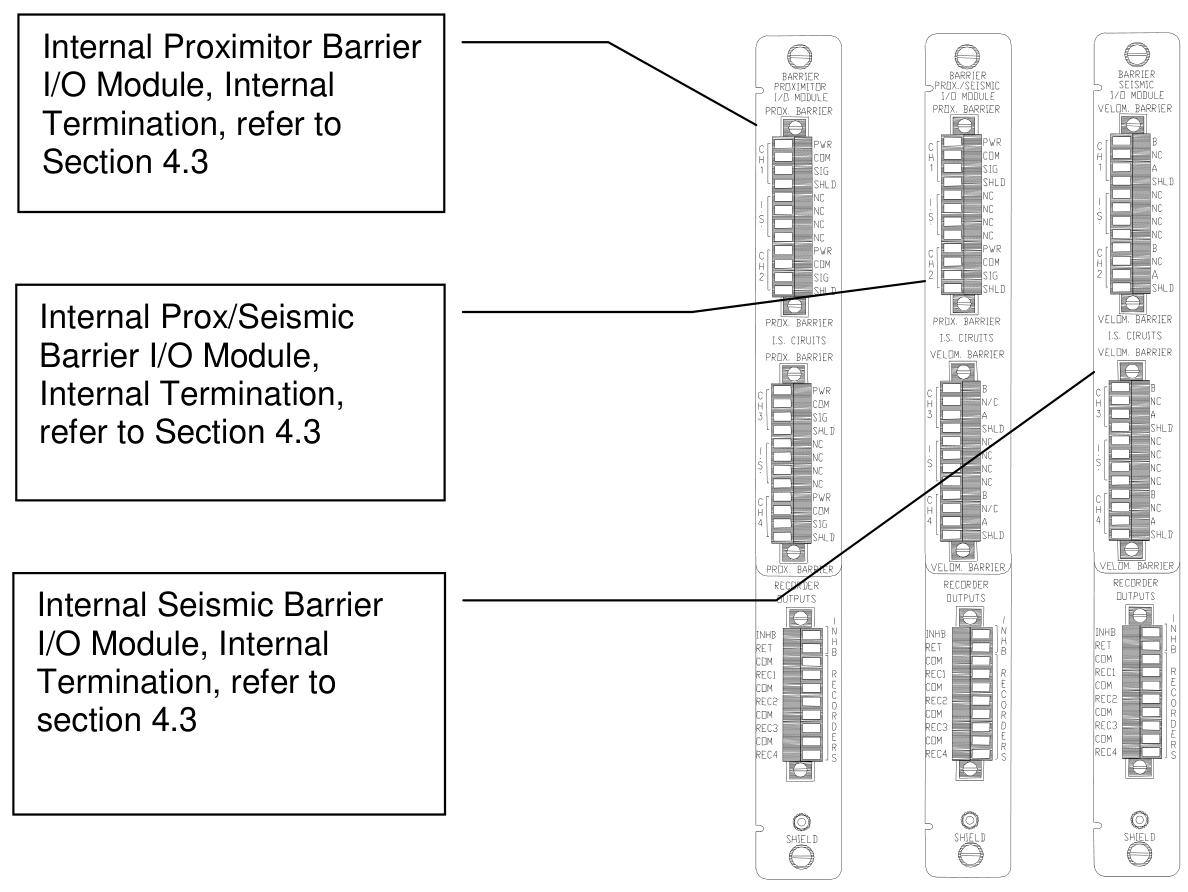
Input module: support multiple I/O modules, including internal terminal, external terminal, TMR terminal and terminal module with barrier, and adapt to different sensor wiring requirements (such as Proximitor, accelerometer, speed sensor).
Signal processing: Each channel integrates filtering, amplification, and digitization circuits, supporting bandpass, high pass, and low-pass filtering, with a configurable frequency response range (such as radial vibration channels supporting 1 Hz to 4000 Hz).
Communication interface: communicates with other modules through the rack backplane, supports serial protocols such as RS-232/485, and can be connected to the upper computer for data monitoring.
TMR redundancy mechanism
Voting logic: In the TMR configuration, three monitoring modules vote 2 out of 3 for the input signal. If the deviation between the output of one module and that of other modules exceeds the set threshold (such as% Comparison), event logging will be triggered.
Input configuration:
Bus configuration: A single non redundant sensor signal is distributed to three modules through the bus.
Discrete configuration: Three redundant sensors are connected to three modules respectively to improve reliability.
Data output and status monitoring
Proportional value output: Output different parameters based on channel type, such as Direct (peak to peak), 1X/2X amplitude, phase lag, etc. for radial vibration; Gap (gap voltage) and Direct (axial displacement) at the thrust position.
Status identification: Feedback module health status, communication status, and alarm events through LED (OK, TX/RX, BYPASS) and event logs (System Event List, Alarm Event List).
Configuration Guide
Software Configuration Tool
Use 3500 Rack Configuration Software for parameter settings, with core configuration items including:
Channel type: Select radial vibration, thrust position, etc. Different types correspond to different filtering and scaling factors.
Full range: For example, radial vibration Direct can choose 0-10 mil pp (peak to peak), and acceleration can choose 0-20 g pk (peak to peak).
Alarm threshold: Set the Alert/Alarm 1 and Danger/Alarm 2 thresholds for each proportional value, and support lag adjustment (e.g., hysteresis is 1/64 of full scale).
Filter parameters: Set the cut-off frequency of the high/low-pass filter (e.g. acceleration channel supports 3 Hz to 30 kHz).
Example of Key Parameter Configuration
Radial vibration channel:
Select a 3300-8 mm Proximitor sensor and set the Scale Factor to 200 mV/mil.
Set the 1X Amplitude full-scale to 10 mil pp, the Alert threshold to 6 mil pp, the Danger threshold to 8 mil pp, and the delay time to 1 second.
Thrust position channel:
The Zero Position voltage is set to -9.75 Vdc (corresponding to the center value of the gap), the full range is set to 25-0-25 mil, and the direction is set to “Forward Probe” (displacement increases when the rotor moves towards the probe).
Key points of TMR configuration
Three monitoring modules need to be installed adjacent to each other and configured with Comparison Voting (if comparing 1X Amplitude, a deviation of 5% is allowed).
Bussed External Termination Block is used for bus configuration, while three independent sensors and terminal blocks are used for discrete configuration.
I/O modules and wiring
Module type and function
Internal terminal module: directly connected to sensors and recorders, suitable for non hazardous areas, wiring should pay attention to electrostatic protection (such as using anti-static wrist straps).
Internal Barrier Module: Integrated Zener Barrier, suitable for explosion-proof areas (such as Class I, Division 1), to restrict energy flow into hazardous areas.
External terminal module: Connect the sensor with a 25 pin cable and the recorder with a 9-pin cable to simplify the internal wiring of the rack.
Wiring specifications
Proximitor sensor: The power supply (PWR) is connected to -24 Vdc, the signal (SIG) is connected to the channel input, and the shielding layer (SHLD) is grounded.
Seismic sensors (such as Velomitor) require series connection of resistors and capacitors (such as 4 k Ω resistors+10 μ F capacitors) for signal conditioning.
TMR wiring: In discrete configuration, three sensors are connected to independent channels of three modules, and in bus configuration, sensor signals are shared through a Bussed Terminal Block.
Maintenance and testing
Regular verification testing
Testing cycle: It is recommended to conduct it once a year. If the equipment is a critical unit or operates in harsh environments, it can be shortened to once every quarter.
Testing equipment: function generator, multimeter, oscilloscope, Keyphasor Multiplier/Diverder, etc.
Test steps (taking radial vibration channel as an example):
Simulate sensor signals (such as a 100 Hz sine wave with a peak to peak value of 2 V).
Verify the display accuracy of proportional values such as Direct and 1X Amplitude (error ≤ ± 1% of full scale).
Trigger Alert/Arm 1 and Danger/Arm 2 thresholds, confirm that the alarm delay time is consistent with the configuration.
Disconnect the input signal and verify the OK state recovery time (Timed OK Channel Defeat set to 30 seconds).
Scale factor and zero position adjustment
Scale Factor: Used to calibrate the linearity deviation of sensors, such as the default 200 mV/mil for 3300-8 mm Proximitors, which can be adjusted by ± 15%.
Zero Position: For channels such as thrust position and eccentricity, adjust the voltage to make the displayed value zero (such as setting the zero position of thrust position to -9.75 Vdc, corresponding to mechanical zero position).
Recorder output verification
The 4-20 mA output should correspond to the full-scale proportional value. For example, when the full-scale is 10 mil pp, 20 mA corresponds to 10 mil pp, and 4 mA corresponds to 0 mil pp, with an error of ≤± 1%.
Troubleshooting
LED fault diagnosis
OK light off: It may be due to module failure, hardware malfunction, or sensor disconnection. Check the power and wiring, restart the module, or replace spare parts.
BYPASS light on: The channel is bypassed by software or the sensor is faulty. Check the Software Switches configuration and confirm that the sensor is in an OK state.
TX/RX light does not flash: communication failure, check the rack backplane connection and serial port parameters (baud rate, data bits).
Event 62 (I/O Module Mismatch): The I/O module type does not match the software configuration. Check the module model and reconfigure it.
Event 493 (Kph Lost): Keyphasor signal loss. Check the Keyphasor sensor and wiring to confirm if the speed is within the valid range (60-60000 cpm).
Common alarm handling
Alert/Arm 1 trigger: If the vibration value exceeds the threshold, check whether the machine is unbalanced, misaligned, or has bearing faults.
Trigger of Danger/Arm 2: Emergency stop condition, immediately stop the machine and troubleshoot equipment faults. If the shaft displacement exceeds the limit, it may cause dynamic and static friction.
Technical specifications and ordering information
key parameter
Input impedance: Proximitor channel 10 k Ω, TMR configuration with bus mode 50 k Ω and discrete mode 150 k Ω.
Frequency response: The radial vibration Direct channel supports 1 Hz-4000 Hz, and the acceleration channel supports 3 Hz-30 kHz.
Environmental conditions: Operating temperature -30 ℃~65 ℃ (non barrier module), storage temperature -40 ℃~85 ℃, humidity ≤ 95% non condensing.
Spare parts: I/O module (such as 128229-01), terminal block (125808-02 Euro style), cable (129525-0010-01, 10 foot assembly cable).
Safety and Compliance
Explosion proof certification: With barrier module supporting Class I, Division 1 (Groups A-D) and EEx ia IIC, suitable for explosive gas environments.
Static protection: When operating the module, wear an anti-static wrist strap and store it in a conductive bag to prevent static electricity from damaging the circuit board.
Maintenance warning: When hot plugging modules, ensure that the rack is powered off to avoid the risk of short circuit or electric shock caused by live operation.
ABB’s Tmax, Isomax, and Emax series molded case circuit breakers comply with UL 489 and CSA C22.2 standards, covering a current range of 15A to 2500A with a breaking capacity of up to 150kA (480V AC).
The product belongs to the IndustrialIT certification system and can be integrated into the ProtectIT suite, supporting collaborative work with distribution board components. Some models (such as T4 and T5) have e-plug communication interfaces.
Core features
Compact design: The depth of small-sized models is unified (such as 70mm for T1-T3), saving installation space.
Double insulation: Except for Isomax S8, electrical accessories can be installed on site to enhance safety and convenience.
Modular design: supports fixed, plug-in, and pull-out installations, with standardized accessories for easy maintenance.
Product Classification and Technical Parameters
1. Tmax series (15A-600A)
Model subdivision: T1-T5, covering 15A-600A, supporting thermal magnetic or electronic release devices (such as PR221DS, PR222DS/P).
Technical highlights:
T4/T5 has high breaking capacity and low let through energy limitation, reducing the impact of short-circuit current.
The electronic release supports overload (L), short circuit (S/I), and ground fault (G) protection, with adjustable parameters (such as I ₁=0.4-1 × In).
Application scenarios: power distribution, motor protection (MCP), isolation switch (MCS).
2. Isomax series (800A-2500A)
Model subdivision: S6-S8, covering 800A-2500A, using electronic release devices (PR211/P, PR212/P).
Technical highlights:
S6-S7 supports pull-out installation, while S8 is fixed with a breaking capacity of 125kA (480V AC).
Equipped with Modbus/Lon communication interface (PR212/D), it can be integrated into industrial networks.
Application scenarios: Medium to large power distribution systems, emergency power switching.
3. Motor Control and Protection (MCP)
Special models: T2-T3, S6-S8, equipped with adjustable magnetic release (6-12 × In) or electronic release (PR221DS-I).
Function: For three-phase asynchronous motors, it supports instantaneous protection against overload and short circuit, and adapts to different starting modes.
4. Isolation switch (MCS)
Model: Based on T1-T5 and S6-S8, without trip function, used for line isolation or switching.
Key technical parameters
Electrical performance
Rated voltage: AC 480V/600V, DC 500V, supports three-phase/single-phase systems.
Breaking capacity: For example, T2 has a breaking capacity of 65kA at 480V AC, and S8 can reach 100kA at 480V AC.
Release characteristics: thermal magnetic release (fixed/adjustable threshold), electronic release (LSIG four stage protection).
Processor: Adopting a 25MHz 32-bit MC68040 or MC68LC040 microprocessor, the former integrates on-chip instruction and data cache, floating-point processor, while the latter has no floating-point unit.
Bus structure: The local bus is a 32-bit synchronous bus that supports burst transmission and snooping mechanisms. The arbitration priority from high to low is: LAN (82596CA)>SCSI (53C710)>VMEbus>MPU.
2. Memory configuration
DRAM: Supports 1MB, 4MB, or 8MB optional, non interleaved (1MB/8MB) or interleaved (4MB) architecture, with parity check, can trigger interrupt or bus exception in case of error.
SRAM: 512KB with battery backup (powered by Dallas DS1210S), battery life can be maintained for 200 days in the event of a power outage at 40 ° C. The backup power source (VMEbus+5V or onboard battery) needs to be selected through J20 jump pin.
Non volatile storage:
8KB NVRAM (MK48T08) integrates real-time clock, supports BCD format display of hours, minutes, seconds, year, month, and day, and automatically processes leap years.
1MB Flash memory (1 Intel 28F008SA or 4 28F020), can be selected to boot from Flash or EPROM through J22 jump pin.
VMEbus interface: implemented by VMEchip2 ASIC, supporting A24/A32 addresses, D8/D16/D32 data transfer, including DMA controller, interrupt processor, system controller and other functions.
Serial port:
The two ports are driven by the Zilog Z85230 controller and support EIA-232-D (DCE/LTE) or EIA-530 interfaces, configured through the SIM module (SIM05-SIM08).
The baud rate range is 110b/s to 38.4Kb/s, supporting synchronous (SDLC/HDLC) and asynchronous protocols.
Network and Storage:
Ethernet interface: Intel 82596CA controller, supports 32-bit DMA, and each card is assigned a unique MAC address ($08003E2XXXXX).
SCSI interface: NCR 53C710 controller, supporting 32-bit local bus burst DMA, ensuring correct termination at both ends of the bus.
Industry Pack (IP) interface: 4 single size or 2 dual size IP interfaces, controlled by IPIC ASIC, supporting external cable connections.
4. Physical and electrical specifications
Size:
Double height VME board, with a height of 9.187 inches without connectors and a height of 10.309 inches with connectors and front panel, and a thickness of 0.8 inches.
Power Supply:
+5V (± 5%), typical 3.5A, maximum 4.5A;+12Vdc (± 5%) and -12Vdc (± 5%), maximum 100mA.
environment
Working temperature: 0 ° C to 70 ° C (forced air cooling), storage temperature: -40 ° C to+85 ° C, relative humidity: 5% -90% (non condensing).
Installation and configuration process
1. Hardware preparation
Jumping needle configuration:
J1: System controller selection (default enabled, system controller when installing jump pin).
J10: SIM module selection for serial port B (EIA-232-D or EIA-530, DCE/LTE mode).
J20: SRAM backup power selection (VMEbus+5V or onboard battery).
J22: Universal readable jump pin, where GPO3 (pins 9-10) is used to select Flash/EPROM boot mapping.
Safety precautions:
Anti static operation, avoid touching integrated circuits; Disconnect all power sources before installation.
Lithium battery handling: Short circuit, disassembly, and heating are prohibited, and polarity should be noted when replacing.
2. Installation steps
Installation of IP module:
Four IP modules are installed on connectors such as J2/J3, J7/J8, and dual size IP requires adjacent interfaces.
External cables are led out through connectors such as J6 and J5, and users need to provide 50 pin cables themselves.
Installation of VME chassis:
The system controller needs to be installed in slot 1 of the chassis, and non controllers can be installed in any double height slot.
Connect the P1 and P2 connectors to ensure they are securely fastened; Remove the IACK and BG jump pins from the corresponding slots on the chassis backplane.
Transition module connection:
Install MVME712 series transition modules (such as MVME712M, MVME712A) and connect serial ports, SCSI, and Ethernet interfaces through a P2 adapter board.
3. Cable and interface connection
Serial port:
Port 1 (CONSOLE) is connected through a DB-25 connector and defaults to asynchronous mode; Port 2 is configured through the SIM module and transition module.
SCSI and Ethernet:
The SCSI interface is connected through a P2 connector and requires the installation of a terminal resistor; The Ethernet interface is led out through the DB15 connector of the MVME712X transition module.
Debugging Tools and Firmware (162Bug)
1. Firmware Overview
Function: Integrated into Flash/PROM, providing functions such as memory debugging, program loading, hardware diagnostics, etc., supporting system self startup and network startup.
System Mode: configured through ENV commands, supports automatic testing and system booting.
2. Core functions and commands
Memory operation:
MD: Displays memory content, supports byte/word/long word formats, and can be disassembled (DI option).
MM: Modify memory data and support direct writing of assembly instructions.
Program execution:
GO: Execute the program from the specified address and support breakpoint setting (BR command).
GT: Execute to a temporary breakpoint for single step tracking.
Disk and Network:
BO/BH: Start the operating system/load programs from the disk and pause.
NBO/NBH: Start the system through network (TFTP/BOOTP) and support IP configuration.
Diagnostic tool:
IOC/IOP: Directly operate the disk controller to test hardware functionality.
CNFG/ENV: Configure onboard information blocks (BIBs) and environment parameters (such as startup latency, memory mapping).
3. Automatic start mechanism
Autoboot: After powering on, it scans disk devices and starts in order of LUNs, which can be interrupted by pressing the<BREAK>key.
Network Boot: Obtain IP through RARP/BOOTP, load boot files through TFTP, and support diskless system boot.
ROMboot: User defined boot code that meets memory mapping and checksum requirements.
Safety and Compliance Standards
Electromagnetic Compatibility (EMC)
The device complies with FCC Part 15 Subpart J Class A standards and can avoid interference when used in commercial environments; If there is interference in the residential environment, users need to take measures on their own.
Safety operation standards
Grounding: Use a three core power cord to ensure that the chassis is grounded (connect the green wire to a safe ground).
Prohibited environment: Do not operate in flammable gas environments.
Maintenance restriction: Only authorized personnel are allowed to open the chassis, operate after power off and discharging.
Warning signs
SYSFAIL * signal: If a memory verification error, low battery voltage, or other fault is detected after power on, the VMEbus SYSFAIL * signal will be asserted.
LED indicator lights: FAIL (red) indicates hardware failure, RUN (green) indicates local bus activity, SCON (green) indicates system controller status.
Summarize
The MVME162 embedded controller, as a classic VMEbus architecture product from Motorola, integrates high-performance processors, rich interfaces, and reliable memory systems, making it suitable for industrial control, embedded computing, and other scenarios. The document provides users with full process support from hardware deployment to system startup through detailed hardware instructions, installation procedures, and debugging tool guides, while emphasizing security standards and compatibility design to ensure stable device operation.
TU810/TU810V1 is a 16 channel 50V compact module terminal unit (MTU) designed specifically for ABB System 800xA automation systems, and is a key component of the S800 I/O system. As a passive interface unit, its core function is to achieve electrical connection between field wiring and I/O modules, while carrying the transmission and distribution of Module Bus signals. This MTU adopts a modular design, supports mechanical keying configuration, ensures compatibility with different types of I/O modules, and is suitable for signal access and system expansion in industrial automation scenarios.
Core functions and technical features
Module Bus Management
As the physical carrier of the Modulus Bus, TU810V1 is responsible for distributing bus signals to connected I/O modules and the next level MTU, forming a chain topology structure.
By shifting the output position signal to generate I/O module addresses, automatic addressing is achieved, simplifying the system configuration process.
Mechanical key control configuration system
Equipped with two sets of six position mechanical keys, compatible with the full range of S800 I/O modules such as AI810, AO810, DI810, DO810, etc. through different combinations (a total of 36 configurations).
Keying is only for mechanical positioning and does not affect electrical functions, but it can effectively prevent module misconnection and improve installation reliability.
Signal and power connection
16 channel on-site signal interface: supports standard industrial signals (such as 4-20mA, 0-10V, etc.), with a maximum current of 2A per channel.
Process power connection: Provide 2 × 2 or 5 × 2 power terminals (0V common terminal), supporting a maximum current of 5A, to meet the power supply requirements of sensors and actuators.
DIN rail installation: supports horizontal (up to 55 ℃) and vertical (up to 40 ℃) installation, with grounding locking device to ensure electromagnetic compatibility.
Compact structure: Size 170 × 64 × 64mm (height × width × depth), weight only 0.17kg, saving control cabinet space.
Protection level: IP20 (preventing solid foreign objects from entering), suitable for indoor industrial environments, pollution level 2 (IEC 60664-1).
Electrical and Environmental Parameters
Electrical performance
Dielectric strength: 500V AC test to ensure insulation safety between channels.
Overvoltage category: Compliant with IEC 60664-1 standard, suitable for industrial grade power systems.
EMC compatibility: Following EN 61000-6-4 (emission standard) and EN 61000-6-2 (immunity standard), it has strong electromagnetic interference resistance.
Environmental adaptability
Temperature range: working temperature 0-55 ℃, storage temperature -40-70 ℃, supports wide temperature operation.
Humidity conditions: 5% -95% without condensation, meeting the requirements of humid environments (IEC 61131-2).
Corrosive atmosphere: Complies with ISA-S71.04 G3 grade and is suitable for moderately corrosive industrial scenarios such as chemical and metallurgical industries.
Certification and Compliance
Safety certifications: CE, UL 508, cULus (Hazardous Area Class 1, Division 2/Zone 2), ATEX Zone 2, supporting applications in explosion-proof areas.
Classification society certification: ABS, BV, DNV-GL, LR, RS, CCS, applicable to ship automation systems.
Environmental standards: RoHS (EN 50581:2012) and compliance with the WEEE directive, supporting green manufacturing.
Digital Output (DO): DO810, DO814, DO815, DO840, DO880
Pulse/Count Input (DP): DP820, DP840
Application scenarios and system integration
Typical application areas
Process automation: signal acquisition and control in the chemical, petroleum, and power industries, such as temperature, pressure, and flow sensor integration.
Mechanical manufacturing: digital input/output control of machine tools and production lines (such as solenoid valves, encoder signal processing).
Ship and Maritime: Engine room monitoring, deck equipment control, meeting the requirements of marine environmental certification.
System topology
Chain extension: Multiple MTUs are connected in series through a Modulus Bus, supporting maximum I/O point expansion and suitable for large control systems.
Redundant configuration: Although MTU is designed as a single channel, it can be combined with redundant I/O modules to improve system reliability.
Installation and wiring precautions
Grounding requirement: Reliable grounding through DIN rail latch to reduce electromagnetic interference.
Cable management: It is recommended to use shielded cables and lay signal and power cables separately to avoid crosstalk.


![MVME162-031 MOTOROLA 逻辑控制主板处理模块[品牌 价格 图片 报价]-易卖工控网](https://img2.fr-trading.com/0/5_779_2374010_651_659.jpg.webp)