Call us 24/7uaedcs@163.com
Welcome to the official website of CNIACS Automation Technology Co., Ltd!
Call us 24/7uaedcs@163.com

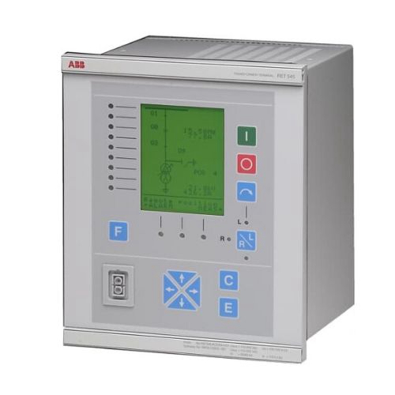
ABB REF 541, REF 543, and REF 545 feeder terminals

Product overview

REF 541, REF 543, and REF 545 feeder terminals are equipment developed by ABB for the protection, control, measurement, and monitoring of medium voltage power grids, and are part of ABB’s substation automation system. They can adapt to different types of switchgear (such as single bus, double bus, and duplex systems) as well as multiple network types (such as neutral insulation networks, resonant grounding networks, and partial grounding networks), and can also be applied to the protection and control of medium-sized three-phase asynchronous motors and parallel capacitor banks for reactive power compensation. The main difference between these three devices lies in the number of digital inputs and outputs.

Core functions

Protection function

It includes multiple types of protection, such as non directional and directional overcurrent and ground fault protection, residual voltage protection, overvoltage and undervoltage protection, thermal overload protection, circuit breaker fault protection, and automatic reclosing.

The protection function based on current measurement can use Roche coils or traditional current transformers, while the protection function based on voltage measurement can use voltage dividers or voltage transformers.

control function 

Support local and remote control of switchgear, status indication of switchgear, and interlocking at interval and station levels.

Measurement function

Capable of measuring phase current, phase to phase and relative ground voltage, residual current and voltage, frequency, power factor, active and reactive power, and electrical energy.

The standard configuration includes pulse counter inputs, with varying quantities depending on the model (7 for REF 541 and 10 for REF 545).

Status monitoring function

Including circuit breaker status monitoring, trip circuit monitoring, and internal self-monitoring of feeder terminals.

Other functions

Such as synchronous inspection, frequency protection, capacitor bank protection and control, current and voltage harmonic measurement, etc.

Equipped with RTD/analog modules for temperature measurement, current/voltage measurement, and mA output.

Data recording and communication

Transient disturbance recorder: capable of recording 16 current or voltage waveforms and 16 logical digital signals, with a sampling frequency of 2kHz at rated frequency 50Hz and 2.4kHz at 60Hz. The recording can be uploaded and converted to COMTRADE format.

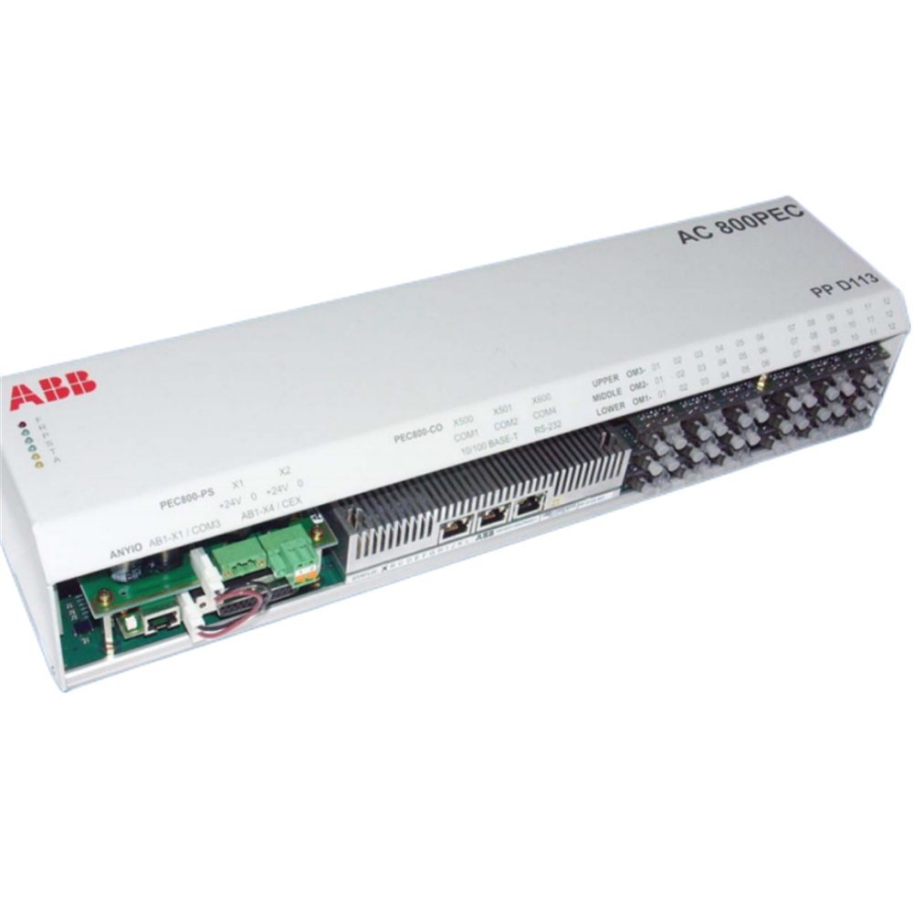
Communication: Provides two communication interfaces, one for local communication with PC and the other for remote communication through substation communication system, supporting SPA and LON serial communication protocols.

Software and hardware configuration
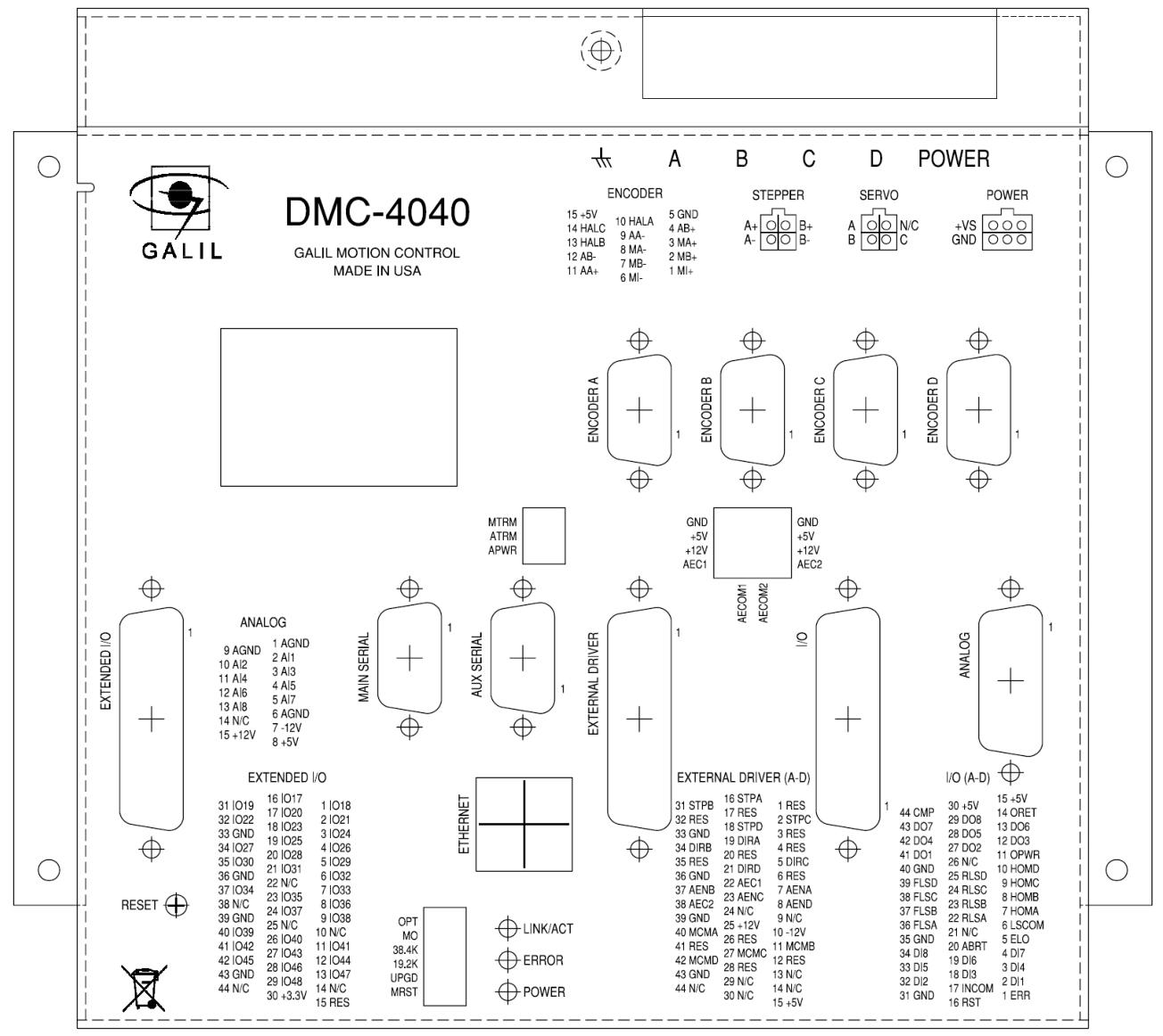
Hardware

Analog channels: Depending on whether sensors are included, there are 9 (no sensors) or 10 (with sensors) analog channels, as well as virtual channels for calculating neutral current and residual voltage.

Digital input: voltage controlled and optically isolated, partially programmable as a pulse counter, with a pulse counting frequency of up to 100Hz, and two global parameters for suppressing digital input oscillations.

Digital output: divided into high-speed power output (HSPO), power output (PO), and signal output (SO).

Display panel: equipped with a fixed display screen or external display module, the display panel includes multiple buttons and indicator lights for operating and indicating device status.

Software

It can be configured through the CAP 505 relay product engineering tool, including basic terminals, protection and logic function blocks, control and measurement functions, etc.

Support the use of relay configuration tools to program PLC functions (such as interlocking and alarm logic), using functional block diagram language.

ABB REF541EM115AAAA feeder terminal Reasonable price - SAUL ELECTRIC

Technical Parameter

Environmental conditions: The specified working temperature range is -10…+55 ° C, the transportation and storage temperature range is -40…+70 ° C, the front protection level of the shell is IP 54, and the back connection terminal is IP 20.

Power supply: There are two basic versions of power modules, PS1 and PS2, and the input voltage and operating range vary depending on the model.

Input and output parameters: including voltage, current range, and accuracy of digital input and output, analog input and output, etc..

Application scenarios

Suitable for various application scenarios of medium voltage power grids, such as different types of switchgear and networks, as well as protection, control, and monitoring of medium-sized three-phase asynchronous motors, parallel capacitor banks, etc. Specific application examples include utility incoming lines, feeders, measuring cabinets, ring/mesh network cable feeders, etc.

Major function 

Protection function: With multiple types of protection, it can comprehensively ensure the safety of the power system. In terms of current protection, overcurrent directional protection has 8 thresholds with freely programmable tripping characteristics, ground fault directional protection has 2 thresholds, and ground fault directional fan-shaped protection has 10 thresholds, which can accurately detect and respond to abnormal current situations. Voltage protection can monitor and protect the system voltage, preventing damage to equipment caused by overvoltage or undervoltage. It also covers differential protection, power direction protection, distance protection, etc., which can be used to protect multiple system components and provide reliable protection solutions for different types of faults. In addition, functions such as automatic reclosing, frequency monitoring, synchronization detection, and fault recording have further enhanced the stability and reliability of the system.

Control function: Supports multiple operating state switches, including running, testing, setting state switches, as well as local and remote state switches, making it convenient for operators to flexibly control equipment according to actual needs. Equipped with closing, opening and emergency opening functions, ensuring effective control of the equipment in different situations. Various interlocking functions are set up in the software, and the interlocking functions implemented through software settings can effectively prevent misoperation and ensure the safety of equipment and personnel.

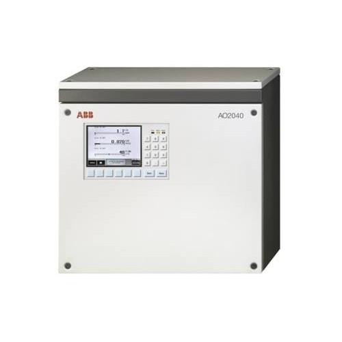
Measurement function: It can accurately measure various electrical parameters, including three-phase current, zero sequence current, maximum demand for three-phase current, three-phase/line voltage, zero sequence voltage, active/reactive power, active/reactive electricity degree, power factor, frequency, etc. The measured values can be displayed on the LCD screen as numbers and LED bar charts, visually presenting the system’s operating status and providing accurate data reference for operators.

Communication function: Supports multiple communication protocols such as RS485, Modbus, IEC 61850, DNP3.0, etc., and can exchange data with different devices and systems. Adopting fiber optic connection, it has the characteristics of simple wiring, strong anti-interference ability, and high reliability, which can achieve real-time information processing and perfect system management, facilitate networking, and meet communication needs in different scenarios.

Monitoring and diagnostic functions: capable of effectively monitoring primary equipment, such as monitoring spring charging time (when applicable) and trip coils, to promptly identify potential equipment issues. Equipped with a self diagnostic program that can continuously check the status of hardware and software modules. The binary input and output module is equipped with watchdog contacts, which are triggered in the event of a fault or power outage. The analog input channel can be selected for monitoring, detecting disconnection from the instrument transformer or sensor connection, and triggering an alarm.

Power quality function: It can monitor and analyze the power quality of the power system, provide data support for optimizing power quality, and ensure that the power system provides high-quality power for various equipment.

PLC function: Standardize the wiring of switchgear, simplify production management, reduce the types of spare parts, and facilitate on-site management and operation maintenance. Through flexible software development, engineering design can be simplified, design cycles can be shortened, on-site debugging efficiency can be improved, and it is easy to change the function of the switchgear or adapt to different load properties in the future.

ABB 馈线终端 REF541 数字继电器 - 启明自动化

ABB UNITOL 1000 series automatic voltage regulator

Product overview

The ABB UNITOL 1000 series is a compact, high-performance automatic voltage regulator (AVR), consisting of three models: UNITOL 1005, 1010, and 1020, designed specifically for low-power range applications, setting a new benchmark in the industry with functionality, reliability, and connectivity. This series adopts separate communication and control processors, equipped with non-volatile flash storage for event and data logs, supports Ethernet time synchronization and event timestamps, and is suitable for various industrial scenarios.

Product model and core parameters

UNITROL 1005:5A continuous, 10A peak, for low-end excitation applications, shares software source code and simulation model with 1010/1020, supports USB, Ethernet, no HMI, analog I/O is 2 inputs, digital I/O is 8 inputs+4 outputs

UNITROL 1010:10A continuous, 20A peak, compact device with limited functionality, same mechanical size and interface as 1020, supports Ethernet RS485(Modbus RTU/VDC)、USB, Analog I/O consists of 3 inputs and 2 outputs, while digital I/O consists of 4 inputs and 8 inputs/outputs

UNITROL 1020:20A continuous, 38A peak, high performance, with a local human-machine interface, comprehensive functions, interface identical to 1010, I/O configuration identical to 1010, and an intuitive local control panel added

Main functions and features

Control mode: Supports automatic voltage regulator (AVR), excitation current regulator (FCR), power factor regulator (PF), reactive power regulator (VAR), etc., and can achieve disturbance free switching between various modes.

Limiter and protection: including excitation current limiter (minimum/maximum), PQ minimum limiter, motor current limiter, V/Hz limiter, motor voltage limiter, etc., to ensure the safe and stable operation of synchronous motors; It has functions such as soft start, voltage matching, and rotating diode monitoring.

Software Function Package: Provides four versions: ECO, LIGHT, BASIC, and FULL, ranging from basic functions to advanced features such as synchronization, event recording, data recording, and real-time clock. The FULL version can also add a Power System Stabilizer (PSS) option, which complies with the IEEE 421.5-2005 standard.

Communication capability: Supports protocols such as Modbus RTU, Modbus TCP, CAN, etc., equipped with Ethernet and USB ports for easy connection to debugging tools and remote access.

Environmental adaptability: Designed for wide temperature environments and harsh industrial conditions, it can be directly installed on machines and has high EMC immunity.

Debugging and maintenance tools

CMT 1000 is a debugging and maintenance tool for this series, which connects devices via USB or Ethernet. Its functions include:

Set parameters and adjust PID to ensure stable operation;

Comprehensive monitoring system to assist in identifying and locating issues during on-site debugging;

Provide functions such as a main window (displaying access modes and device information), a settings adjustment window (viewing control modes, alarms, etc.), and an oscilloscope (recording and analyzing signals).

application area 

Widely used in land-based power plants (based on diesel engines, gas/steam turbines, water turbines), ships (electric propulsion and auxiliary power supply), traction (diesel electric locomotives), wind energy (based on directly connected synchronous motors), synchronous motors, and variable speed applications.

Working principle

Signal acquisition: Real time acquisition of key parameters such as three-phase voltage, current, and grid voltage of the motor through measuring terminals, as a basis for adjustment.

Deviation calculation: Compare the actual voltage of the collected motor with the set target voltage to calculate the deviation value.

Control regulation: Based on the deviation value, the built-in control algorithm (such as PID regulation) is used to generate excitation current regulation commands, and the current size of the excitation system is adjusted through the IGBT power output stage.

Dynamic response: Quickly respond to changes in the power grid or load, adjust the magnetic field strength of the motor by changing the excitation current, and then correct the motor terminal voltage to stabilize it within the set range.

Protection and Limitation: Equipped with multiple limiters (such as excitation current, V/Hz limit, etc.), it automatically intervenes when parameters exceed the safe range to prevent motor overload or damage, ensuring the safe operation of the system.

ABB PCD235C101 3BHE057901R0101 AC800pec Excitation

Technical specifications

Input/output configuration

Digital input: With 16 digital input channels, it can quickly and accurately collect various switch signals on site, such as the start stop status of equipment, limit switch signals, etc., providing real-time and accurate equipment operation status information for the control system.

Analog Input: Equipped with 4 analog input channels, it can convert continuously changing analog signals from sensors, such as temperature, pressure, flow rate, and other physical quantities, into digital signals that can be recognized by the control system. It also has high resolution and low noise characteristics to ensure the accuracy of signal acquisition.

Digital output: Equipped with 12 relay outputs, it can directly drive external loads and control various actuators such as contactors, solenoid valves, etc. Its output contacts have high load capacity and electrical isolation performance, ensuring stable and reliable execution of control instructions.

Analog output: Four analog output channels are used to output continuously changing analog signals, which can accurately control devices such as regulating valves and frequency converters, and achieve precise adjustment of parameters such as flow rate and speed in industrial processes.

Communication capability

Ethernet interface: Supports Ethernet communication protocol, has high-speed data transmission capability, can quickly exchange data with upper computer, other intelligent devices or control systems, facilitates remote monitoring, data sharing and system integration, and meets the needs of equipment interconnection and intercommunication in the Industry 4.0 era.

Serial communication (RS232, RS485): Equipped with both RS232 and RS485 serial communication interfaces, it is compatible with various traditional devices and sensors. It plays an important role in scenarios where communication speed is not high but communication distance and anti-interference ability are required, providing convenience for different types of industrial equipment to access the system.

Power characteristics: Powered by a 24V DC power supply, this power supply specification is widely used in the industrial field and has the characteristics of high stability, easy access, and maintenance. The module is equipped with an efficient power management circuit that can effectively suppress the impact of power fluctuations on the system, ensuring stable operation in complex industrial power environments.

Memory and processing performance

Memory configuration: With 128 kB of RAM for real-time storage and processing of data, it can quickly respond to various data read and write operations during system operation; 512 kB Flash is used to store programs and important data, which will not be lost even after the system loses power, ensuring that the system can quickly recover to normal operation after restarting.

Processing capability: Built in high-performance processor with powerful computing and logic processing capabilities, capable of quickly processing large amounts of input data, executing complex control algorithms, and outputting control instructions in a timely manner, meeting the requirements for real-time and high-precision control in industrial automation production processes.

​Environmental adaptability

Working temperature range: It can work stably within the temperature range of -20 ° C to 55 ° C. Whether in cold northern industrial environments or hot southern production workshops, it can ensure the normal operation of the system and adapt to temperature conditions in different regions and industrial scenarios.

Protection level: reaching a certain protection level standard, such as good dust and splash resistance, can effectively resist the erosion of pollutants such as dust and water droplets in industrial environments, ensure the normal operation of electronic components inside the module, and extend the service life of equipment.

Core Features and Advantages

Ultra short cycle time: capable of achieving control cycles as low as 100 μ s, and even handling extremely fast tasks as low as 25ns, while also considering second level tasks for long-term transient operation, meeting control tasks with different speed requirements.

Powerful processing capability: Combining the floating-point computing performance of the CPU with the flexibility and high-speed capability of FPGA, it can efficiently handle complex control algorithms such as model predictive control.

Convenient programming tool: supports multiple programming methods, including using ABB’s Control Builder (supporting IEC61131-3 language) for system engineering design, and utilizing MATLAB ®/ Simulink ®  Develop products and controls (automatically generate and download code), and use VHDL to handle extremely fast processes, easily bridging the gap from simulation to implementation.

Comprehensive integration: It can be fully integrated into ABB’s System 800xA automation system, achieving seamless integration with the factory control system and ensuring transparent data exchange and control throughout the factory.

Innovative FPGA Applications: Capable of flexibly utilizing FPGA to integrate protocols and application functions into devices without increasing additional processor load.

Optical communication technology: using optical communication to improve communication speed and electromagnetic interference resistance, and achieving potential free connection, eliminating the need for isolated transmitters.

Industrial grade hardware: The hardware has no moving parts, possesses industrial grade reliability, has a long lifecycle, is easy to upgrade, and can adapt to harsh environments.

Modular structure: It can be flexibly adjusted according to the application scale, suitable for large industrial factories, propulsion systems, and small compact products. At the same time, the software provides pre configured packages to adapt to different processing performance and I/O speed requirements.

Software and hardware architecture

Hardware architecture: divided into three performance levels, corresponding to different cycle times, perfectly matched with the three-level software structure. We provide fast I/O systems and slow I/O systems. Fast I/O is connected through fiber optic links, with a data throughput of less than 100 μ s, while slow I/O uses modules from ABB S800 system.

Software architecture: divided into three levels, Level 1 is used for systems engineering to handle slow tasks (with a cycle as low as 1ms); Level 2 is used for product and control development, handling fast tasks (with a cycle time as low as 100 μ s); Level 3 is used for communication and extremely fast logic processing, handling extremely fast tasks (as low as 25ns).

Application scenarios

Traction field: capable of working in a wide temperature range of -40 to+70 ° C and vibration environment that meets traction standards, suitable for compact applications with limited space.

In the field of power generation: In the excitation system, with modular architecture and redundant subsystems, reliability is improved. When the main controller fails, the hot standby second controller can take over the work.

Industrial process: In rolling mills, thickness control solutions developed based on MIMO control concepts can reduce thickness deviation by up to 50% and improve product quality.

Development and Engineering Advantages

Adopting a model-based design process using MathWorks ®  The tool is a single development platform that integrates system simulation, code generation, download, and debugging, reducing time consumption and errors in traditional development processes, shortening development cycles, lowering development and engineering costs, accelerating product launch time, saving manpower and resources in engineering and software development, and improving asset return on investment.

Connectivity and Scalability

Rich communication protocols: Supports multiple native and additional communication protocols, such as Profibus Master DPV1, Modbus RTU, MMS, Profinet I/O, etc., to ensure connectivity with various devices and systems.

Flexible I/O configuration: Fast and slow I/O can be configured according to project requirements. Fast I/O is connected through fiber optic links and has advantages such as high speed, electromagnetic interference resistance, and potential free connection; Slow I/O can add modules to ABB S800 system.

**Scalability * *: Hardware can be expanded from compact configurations to large modular systems, and software provides pre configured packages to adapt to different processing performance and I/O speed requirements, meeting various application scales.

ABB PPD113-B03-23-111615 Excitation system Sincere service - SAUL ELECTRIC

ABB GFD233 3BHE022294R0102 Redundant System

Product Overview

ABB GFD233 3BHE02294R0102 is a widely used redundant system control module, which is a key component of ABB’s rich product line. It is designed for scenarios with extremely high requirements for system stability and reliability in complex industrial environments. It plays a core role in distributed control systems (DCS) and programmable logic controller (PLC) systems, and can accurately and efficiently achieve automated control of various industrial processes.

Technical specifications

Communication interface: This module supports multiple mainstream communication protocols, such as Profibus DP, Profinet, and Modbus TCP. This enables it to easily achieve seamless communication with devices of different brands and models, greatly improving the convenience and flexibility of system integration. Whether it is data collection from on-site devices or instruction transmission with the upper computer, they can be stably and efficiently completed through these communication interfaces.

I/O channels: With up to 32 I/O channels, it can meet the needs of large-scale data input and output. Through these channels, the module can receive real-time signals from field devices such as sensors and switches, and accurately send processed control instructions to the executing mechanism, ensuring precise control of the industrial production process.

Power supply: Powered by a 24V DC power supply, this common DC power supply specification not only has high stability and reliability, but is also easy to obtain and maintain. A stable power input provides a solid guarantee for the continuous and stable operation of the module, ensuring reliable operation even in industrial environments with minimal power fluctuations.

Installation method: Supports DIN rail installation, which is a standardized industrial installation method with the characteristics of convenient installation, firm and reliable. In the industrial control cabinet, the module can be fixed on the DIN rail through simple card mounting operation, which is convenient for later maintenance, replacement, and system expansion.

Protection level: reaching IP67 protection level, which means that the module has excellent dust and water resistance capabilities. Even in harsh industrial environments such as dusty mines and damp chemical workshops, it can effectively resist the invasion of dust and water, ensure the normal operation of modules, and reduce the probability of failures caused by environmental factors.

Application Fields

Chemical industry: In the process of chemical production, there are numerous complex chemical reactions and process flows involved, which require extremely high stability and reliability of control systems. The ABB GFD233 module can be used to precisely control key parameters such as reaction temperature, pressure, and flow rate, ensuring the safe and stable operation of chemical production processes, and avoiding production accidents and product quality issues caused by control errors.

Petroleum industry: This module is widely used throughout the entire industry chain from oil extraction to refining and chemical product production. At oil extraction sites, it can be used to control the operation of drilling equipment and oil extraction equipment; In refineries and chemical plants, automation control of various production equipment can be achieved, such as temperature, liquid level, and flow control of distillation towers, reaction vessels, and other equipment, to ensure efficient and safe production in the petroleum industry.

Electronics industry: The electronic manufacturing process requires strict precision and stability of production equipment. This module can be used for the control of automated production lines, achieving precise control over process links such as electronic component placement, soldering, and testing, and improving the production quality and efficiency of electronic products.

Power industry: In power plants, whether it is thermal power generation, hydropower generation, or wind power generation, ABB GFD233 modules can play an important role. It can be used for controlling the excitation system of generators to ensure stable output of electrical energy; It can also be used for substation automation control in power systems to achieve real-time monitoring and control of power equipment, ensuring the safe and stable operation of the power system.

Product advantages

Modular design: Adopting advanced modular design concepts, users can flexibly configure modules according to actual needs, facilitating system expansion and customization. When the production scale expands or the process flow changes, only the corresponding modules need to be added or replaced to meet the new control requirements, without the need for large-scale transformation of the entire control system, greatly reducing the cost and difficulty of system upgrade and maintenance.

High performance processing capability: With powerful processing capabilities, it can quickly respond to and process various complex control instructions. In the process of industrial automation production, facing the task of collecting, analyzing, and processing a large amount of real-time data, this module can quickly make decisions and execute corresponding control actions to ensure the efficient and stable operation of the production process, effectively improving production efficiency and product quality.

High stability and reliability: After rigorous quality testing and reliability testing, it can still maintain stable and reliable operation in harsh industrial environments. Whether it is extreme environmental conditions such as high temperature, low temperature, high humidity, strong electromagnetic interference, or long-term continuous operation, this module can consistently maintain high performance, provide reliable control guarantees for industrial production, reduce production downtime caused by equipment failures, and lower production losses for enterprises.

Self diagnostic function: Built in advanced self diagnostic system, capable of real-time monitoring of module operation status. Once a hidden fault is discovered, the system will immediately issue an alarm and provide detailed fault information to prompt users of the location and cause of the fault, helping them quickly locate and solve the problem, greatly improving the efficiency of equipment maintenance and reducing equipment maintenance costs.

Remote monitoring and maintenance: Supports remote monitoring and maintenance functions. Users can remotely connect to the module through the network to obtain real-time operation data and status information of the module, and perform remote debugging, parameter setting, and fault diagnosis of the module. This feature not only facilitates user management and maintenance of equipment, but also effectively reduces the workload and travel costs of on-site maintenance personnel, especially suitable for widely distributed industrial production systems.

Galil DMC-40×0 series motion controller

Overview

Controller Introduction

The DMC-40×0 series is a Galil high-performance independent controller that supports up to 8-axis control, with high-speed communication, non-volatile program memory, faster encoder speed, and improved EMI reduction wiring.

Provides two communication channels, RS-232 (2-channel, maximum 115K baud rate) and 10BaseT Ethernet, supporting high-speed servo control with up to 22 million encoder counts per second and stepper motor control with 6 million steps per second, with a sampling rate as low as 31.25 µ sec/axis.

Flash EEPROM provides non-volatile memory for storing application programs, parameters, arrays, and firmware, which can be upgraded on-site.

Supported motor types

Standard servo motor with ± 10V command signal

Brushless servo motor with sinusoidal commutation

Stepper motor with step and direction signals

Other actuators (such as hydraulic devices, please contact Galil for more information)

Overview of External Amplifier

Current mode amplifier: accepts analog command signals within the ± 10V range, and the amplifier gain should be set to+10V command to generate the maximum required current.

Speed mode amplifier: The 10V command signal should cause the motor to operate at the maximum required speed.

Stepper motor amplifier: accepts step and direction signals.

Overview of Galil amplifiers and drivers

A1- AMP-430×0 (- D3040, – D3020): Multi axis brushed/brushless amplifier, capable of processing 500 watts of continuous power per axis, accepting 18-80VDC DC power supply voltage.

A2-AMP-43140 (- D3140): Contains four linear drivers for operating small brushed servo motors, requiring ± 12-30 DC voltage input, with an output power of 20W per amplifier and a total power of 60W.

A3-SDM-44040 (- D4040): Stepper driver module capable of driving up to four bipolar two-phase stepper motors, with selectable currents of 0.5, 0.75, 1.0, and 1.4 amperes per phase, and selectable step resolutions of full step, half step, 1/4, and 1/16.

A4- SDM-44140 (- D4140): Microstep module, driving four bipolar two-phase stepper motors with 1/64 microstep resolution (SDM-44140 drives two), with selectable current of 0.5, 1.0, 2.0, and 3.0 amperes per axis.

Beginner’s Guide

Layout and Size

Introduced the layout and size information of DMC-4040 and DMC-4080.

power connection

The power connector information for controllers without Galil amplifiers or when ordering ISCNTL power options, as well as the power connector information for controllers with Galil integrated amplifiers.

Required components

Including DMC-40×0 motion controller, motor amplifier (integrated when using Galil amplifier and driver), power supply for amplifier and controller, brushed or brushless servo motor or stepper motor with optical encoder, cable connected to DMC-40×0 integrated ICM, PC (RS232 or Ethernet for DMC-40×0), GalilTools or GalilTools Lite software package.

Installation steps

Determine the overall motor configuration, install jumpers on DMC-40×0, install communication software, connect 20-80VDC power supply to the controller, establish communication with Galil software, determine the axis for sine commutation, connect to amplifiers and encoders, connect standard servo motors/sine commutation motors/stepper motors, and adjust the servo system.

Hardware connection

Optical isolation input

Including limit switch input, origin switch input, abort input, ELO (electronic lock) input, reset input, and unconfirmed digital input, their functions, wiring, and electrical specifications are introduced.

TTL input

The auxiliary encoder input can be used for general purposes, with one auxiliary encoder per axis, containing two inputs, and can accept TTL level signals, etc.

High power optical isolation output

Introduced its electrical specifications and wiring methods, the outputs 9-16 of the 5-8 axis controller are located on the I/O (E-H) D-Sub connector.

analog input

There are eight analog inputs configured in the range of -10V to 10V, and different ranges and modes can be set through the AQ command. The electrical specifications are introduced.

TTL output

Including output comparison, error output, etc.

Expansion I/O of DMC-40×0 Controller

Provides 32 extended TTL I/O points that can be configured as inputs or outputs in 8-bit increments, and introduces their electrical specifications.

Amplifier interface

Introduced its electrical specifications and overview, as well as the ICM-42000 and ICM-42100 amplifier enable circuits, and the ICM-42200 amplifier enable circuit.

Software tools and communication

RS232 and RS422 ports

Introduced RS-232 and RS-422 configurations, including pin descriptions, configuration methods, baud rate selection, and handshake.

Ethernet configuration

Supports two industry standard protocols, TCP/IP and UDP/IP, and introduces addressing methods including MAC address, IP address, and UDP or TCP port number.

communication protocol

Introduced communication methods with multiple devices and multicast functionality.

Third party software usage

Supports tools such as DHCP, ARP, BOOT-P, and Ping for establishing Ethernet connections, and can communicate with hosts through any application that can send TCP/IP or UDP/IP packets, such as Telnet.

Modbus

An RS-485 protocol is introduced, including its function code, communication level, and examples.

data record

The status information block can be provided through QR commands, which introduces the mapping of data records and the interpretation of bit fields.

GalilTools (Windows and Linux)

It is a software toolset provided by Galil for the current Galil controller, which includes multiple tools and can run on both Windows and Linux platforms.

Create custom software interface

Provide programming tools such as GalilTools communication library, ActiveX Toolkit,. NET API, and DMCWin to facilitate users in developing their own custom software interfaces.

Command Fundamentals

introduce

Provide over 100 commands for specifying motion and machine parameters, which can be sent via ASCII or binary.

ASCII command syntax

The instruction consists of two uppercase letters followed by applicable arguments, terminated with a semicolon or carriage return, and introduces the syntax for specifying axis data and requesting actions.

Binary Command Syntax (Advanced)

The binary communication mode is about 20% faster than ASCII commands. The binary format can only send commands from a PC and cannot be embedded in applications. This article introduces the binary command format and tables.

Controller’s response to data

Return ‘:’ for valid commands and ‘?’ for invalid commands, error codes can be requested through the TC1 command.

Inquire about the controller

There is a set of commands that directly query the controller and return the required data, introducing the query commands and operands.

Sports programming

overview

Provides multiple motion modes, such as independent positioning and jogging, coordinated motion, electronic cam motion, and electronic gear transmission, and introduces application examples applicable to different modes.

Independent axis positioning

Each axis moves independently and follows its own contour. Relevant commands and operands, as well as examples, are introduced.

Independent Jogging

The ability to change speed, direction, and acceleration during motion is introduced, along with relevant commands and operands, as well as examples.

Position Tracking

This article introduces the characteristics and examples of a target that allows absolute position movement to be changed during motion.

Linear interpolation mode

Multi axis motion coordination, maintaining specified vector velocity, acceleration, and deceleration along a specified path, introducing relevant commands and operands, as well as examples.

Vector mode: Linear and circular interpolation motion

Allow the specification of long 2-D paths consisting of linear and circular arc segments, introduce relevant commands and operands, and provide examples.

Electronic gear transmission

Up to 8 axes can be connected to certain main axis electronic gears, and relevant commands and examples are introduced, including bevel gear transmission.

Electronic cam

A motion control mode that supports periodic synchronization of multiple motion axes, introducing relevant commands and examples.

PVT mode

Allowing the definition of arbitrary motion contours for all 8 axes through position, velocity, and time, relevant commands and examples are introduced.

Multi axis coordinated motion

Many applications require multiple axes to move in a coordinated manner, while also requiring smooth motion. An example was introduced.

contour mode

Allowing the specification of curves at any position for 1 to 8 axes, introduces relevant commands and examples, including recording and playback functions.

Stepper motor operation

Introduced the relevant commands for operating stepper motors, smoothing functions, methods for using encoders, and the Stepper Position Maintenance Mode (SPM).

Double loop (auxiliary encoder)

Except for the shaft configured for stepper motor operation and the shaft used for circular comparison, each shaft provides a second encoder interface, and its purpose and related commands are introduced.

**Backlash compensation**

Two methods of using auxiliary encoders for backlight compensation were introduced: continuous dual loop and sampling dual loop.

Motion Smoothing

Smooth motion and reduced mechanical vibration of the system can be achieved through IT and KS commands.

zeroing

The Find Edge (FE) and Home (HM) commands can be used to zero the motor to the mechanical reference point, and the steps and related commands for zeroing are introduced.

High speed position capture (latch function)

The position of the main encoder or auxiliary encoder can be captured within 25 microseconds of external low input signals (or index pulses), and its usage steps and examples are introduced.

Quick update rate mode

It can run at a much faster servo update rate than the default per millisecond, and introduces the update rates and related limitations of different models of controllers.

Application Programming

overview

Provide a powerful programming language that allows users to customize controllers for specific applications. The program can be downloaded to DMC-40×0 memory, freeing up the host for other tasks.

Using DMC-40×0 editor to input program

The GalilTools package or the line editor provided by DMC-40×0 can be used to input and modify programs, and the editing mode commands are introduced.

Program Format

Composed of DMC instructions, action instructions are combined with program flow instructions to form a complete program, introducing the use of tags and special tags.

Comment

You can use the NO command or apostrophe (‘) to add comments to the program.

Executing Programs – Multitasking

Up to 8 independent programs (threads) can run simultaneously, and instructions for starting and stopping threads are introduced.

debugger

Provide commands and operands that help debug applications, such as trace commands, error code commands, stop code commands, etc.

Program flow command

Including event triggers and conditional jumps, the program flow can be changed based on the occurrence of events.

The DMC-40x0 and DMC-41x3 Now Have Twice The Program Memory! | Galil

Mathematics and Function Expressions

Provides a variety of mathematical operators and functions that can be used for data manipulation.

variable

Provides 510 variables that can be used to store mutable parameters, and introduces the definition and assignment of programmable variables.

array

Used for storing and collecting numerical data, this article introduces the definition, assignment, upload and download of arrays, as well as automatic data capture functions.

Data input (numerical and string)

The IN command can be used to prompt the user to enter numerical or string data, introducing the operator data input mode and the use of communication interruption.

Data output (numerical and string)

MG commands can be used to output numerical and string data, introducing message sending, port specification, and formatting.

Hardware I/O

Introduced the usage methods of digital output, digital input, auxiliary encoder input, input interrupt function, analog input, and extended I/O.

Example application

Examples include line cutters, X-Y worktable controllers, speed control through joysticks, position control through joysticks, and backlight compensation through sampling dual loops.

Hardware and software protection

overview

Providing multiple hardware and software functions to check for error conditions and disable motors in case of errors helps protect various system components from damage.

hardware protection

Including output protection lines (such as amplifier enable, error output) and input protection lines (such as universal stop, selective stop, ELO, forward limit switch, reverse limit switch).

software protection

Provides programmable error limits that can set limit values for position errors, introduces programmable position limits, Off On Error functionality, automatic error programs, and limit switch programs.

Troubleshooting

overview

Potential issues are classified into three categories: installation, stability and compensation, and operation. Various symptoms, diagnoses, causes, and remedial measures are introduced.

Operational theory

overview

Discussing the operation of a motion control system, a typical motion control system consists of multiple elements, and the operation can be divided into three levels: closed-loop, motion contour, and motion programming.

Closed loop system operation

Qualitatively and quantitatively explained the operation of the servo system, including the principle of closed-loop control, the causes of instability, and the role of PID filters.

system modeling

Established mathematical models for various elements of the servo system, such as motor amplifier, encoder DAC、 Digital filters and ZOH.

system analysis

Starting from the block diagram model of system elements, analyze to determine the stability of the system.

System design and compensation

Aiming to close the loop with cross frequency and phase margin, the analysis and design methods are introduced.

appendix

Electrical specifications

Electrical specifications including servo control, stepper control, input/output, and power requirements.

Performance specifications

Including performance parameters such as minimum servo loop update time, position accuracy, and speed accuracy.

Quick update rate mode

Introduced the update rate and disabled features in fast mode.

Ordering options for DMC-40×0

Introduced controller board options, CMB communication board options, ICM interconnect board options, and AMP internal amplifier options.

DMC-40×0 power connector

Introduced the Molex connector models and cable connections used.

Integration Components

Detailed descriptions, electrical specifications, mating connectors, and operation information of integrated components such as A1 to A8 were provided.

ABB AO2040-CU Ex Central Unit

The specialized operating guide for ABB AO2040-CU Ex central unit (2G class) serves as a supplement to the main operating manual for the AO2000 series continuous gas analyzer (publication number 42/24-10 EN), containing key information for safe installation, start-up, and operation of the equipment. The “Analyzer Data Sheet” accompanying each device should be used in conjunction with this manual. The symbols “1, 2, 3,…” in the manual indicate safety operation points, and the symbol “●” indicates specific instructions for equipment operation.

Technical Parameter

Compliant with standards: Compliant with DMT 08 ATEX 2018 U 605 standard, explosion-proof mark Ex de IIC T4 Gb, equipment category 2G, suitable for use in Zone 1 and Zone 2 explosion hazardous areas.

Size and weight: The equipment size is not explicitly mentioned, with a weight of approximately 28kg.

Suppress gas related parameters

Gas type: Use air that meets ISO 8573-1 standard level 3 as the suppression gas.

Gas quality requirements: maximum particle size of 40 μ m, maximum oil content of 1mg/m ³, maximum pressure dew point+3 ° C.

Working pressure range: Suppress gas working pressure to 250-500kPa (2.5-5bar).

Power supply parameters

Voltage setting: Before connecting to the power supply, it is necessary to confirm that the equipment voltage setting matches the line voltage. The specific voltage setting value is not explicitly mentioned.

Power protection device: Install suitable protection devices and easy to operate circuit breakers, specific specifications are not explicitly mentioned.

Pressure parameters

Positive pressure inside the system casing: Maintain a positive pressure of approximately 2hPa inside the system casing during operation.

Positive pressure alarm and protection threshold: When the positive pressure is below 0.8hPa or above 15hPa, disconnect the power supply and isolation relay connection circuit inside the system enclosure; When the internal pressure is below 1.2hPa, a status signal is output through passive relay contacts.

ABB AO2040 气体分析仪 - 厦门雄霸

​Electrical connection parameters

Potential compensation connection: External potential compensation connection or protective wire with a minimum cross-sectional area of 4mm ².

Intrinsic safety signal circuit: The total length of the intrinsic safety signal circuit for the condensate water monitor shall not exceed 75 meters, and a 100k Ω resistor shall be installed next to the sensor.

Cable connector specification: M20 threaded connector is suitable for cable outer diameters of 6-12mm.

Safety operation information

General safety requirements: The equipment must be properly handled, stored, installed, set up, operated, and maintained; Only personnel who are familiar with similar equipment and have relevant qualifications can operate it; It is necessary to comply with the content of this manual, equipment safety information, safety precautions for electrical equipment and gas operation, as well as explosion-proof regulations and standards.

Special safety instructions: Follow all explosion-proof safety measures before operation; Do not operate current carrying components in explosive risk environments except for intrinsically safe circuits; Connect the local potential compensation point first; Ensure that the equipment voltage setting matches the line voltage; Before opening the casing, disconnect all power sources and wait for 10 minutes for the power capacitor to discharge; If the equipment is damaged, unable to operate, or has poor storage and transportation conditions, it should be stopped from use.

Installation guide

Unpacking and installation: The equipment weighs approximately 28kg and requires two people to operate. The installation position should be stable; Can be installed in Zone 1 and Zone 2 explosion hazardous areas, and cannot be installed outdoors.

Suppression gas pipeline connection: Use air that complies with ISO 8573-1 Level 3 as the suppression gas; Install the accompanying compressed air conditioning filter to prevent valve damage caused by gas pipeline contamination.

Electrical connection safety precautions: Do not change the internal wiring of the factory, only modify the wiring between the isolation relay and the system controller and I/O board connectors; First, connect the external potential compensation connection or protective wire, with a minimum conductor cross-sectional area of 4mm ²; Electrical circuits need to be firmly fixed, and shielded wires need to pass through metal connectors; The intrinsic safety signal line is only connected to the blue cable connector, with a minimum distance of 8mm from other lines; the communication interface line needs to be connected through factory pre wired isolation relays; Connect the power line to the pressurized enclosure system control unit, do not directly connect it to the system enclosure port.

Electrical connection details: Clarify the application of different types of connectors (light blue M20, black M20, metal M20); The M20 threaded connector is suitable for cable outer diameters of 6-12mm. Unused connectors need to be sealed with original plugs and tightened.

Electrical equipment composition: including isolation relays, terminal blocks, line filters, pressurized enclosure system control units, isolation amplifiers, etc. 

Each device has its specific functions and connection requirements.

Analysis module connection: The system bus and 24VDC cable are components of the pressurized enclosure system, with a length of not less than 1 meter; Connect the system bus cable and 24VDC cable to the central unit according to the steps.

Non intrinsic safety signal line connection: connected to the right side of the isolation relay; The intrinsic safety signal circuit of the condensate monitor is connected through a bright blue cable, with a total length not exceeding 75 meters, and a 100k Ω resistor is installed next to the sensor.

Status signal, potential compensation and power connection: The minimum cross-sectional area of the conductor for potential compensation connection is 4mm ²; Connect the status signal to control unit terminals 21 and 22; Before connecting the power supply, confirm that the voltage settings match, install appropriate protective devices and easy to operate circuit breakers, and connect control unit terminals 15, 17 and PE terminals.

Operation and maintenance

Pre start inspection: Confirm that the installation site conditions, equipment installation firmness, suppression of gas flow, shell integrity, electrical circuit connections, etc. meet the requirements.

Startup steps: Connect the power supply and suppress the gas supply. After the initial purge is completed, switch the solenoid valve to “leakage compensation” and activate the power supply of the equipment inside the system casing; After startup, the “Power”, “Maintenance”, and “Error” LEDs light up, and the screen displays the startup phase and software version, then switches to measurement mode.

Maintenance bypass operation: When there is no explosive environment, the bypass of the pressurized shell system control unit can be activated, which requires approval from the operations manager; Activate and deactivate the bypass according to the steps, and the bypass must be deactivated during normal operation.

Regular inspection: Conduct routine checks according to the pre startup checklist.

Appendix: Application and Design

Application and Design Overview: Used in conjunction with the AO2060 series analysis module to control and monitor the measurement and control process; The system casing is wall mounted and designed to comply with EN 60079-2 “pressurized casing with leakage compensation”; Can access intrinsic safety and non intrinsic safety signal circuits, and the system controller has no battery backup.

Pressure shell system: using air that complies with ISO 8573-1 Level 3 as the suppression gas, with a particle trap at the outlet; Perform preliminary blowdown set by the factory during startup, and maintain a positive pressure of approximately 2hPa inside the system casing during operation; When the positive pressure is lower than 0.8hPa or higher than 15hPa, disconnect the power supply and isolation relay connection circuit of the equipment inside the system casing, and after the pressure is restored, blow and activate again; When the internal pressure is below 1.2hPa, a status signal is output through passive relay contacts.

ABB REF615 feeder protection relay

Product overview

Positioning and Function: REF615 is a specialized feeder protection relay designed for feeder protection, measurement, and monitoring in public substations and industrial power systems. It follows the IEC 61850 standard and supports multiple communication protocols. It can serve as the main protection for overhead lines and cable feeders, as well as backup protection.

Adaptation scenario: According to the pre configuration, it is suitable for the protection of overhead lines and cable feeders in isolated neutral points, resistance grounding, compensation, and solid grounding networks. After specific application settings are given, it can be directly put into use.

Standard configuration

Four configuration types: standard configuration A, B, C, D, supporting different combinations of protection functions, such as configuration A and B supporting directional ground fault protection, and configuration C and D supporting non directional ground fault protection.

Functional differences: Different configurations have differences in the stage settings and directionality of protection functions such as overcurrent, ground fault, and negative sequence overcurrent, as well as varying degrees of support for control, monitoring, and measurement functions.

Protection function

Core protection functions: including three-phase non directional overcurrent (low setting, high setting, instantaneous stage), directional and non directional grounding faults (low setting, high setting, instantaneous stage), negative sequence overcurrent, phase discontinuity, thermal overload, circuit breaker fault protection, three-phase surge detection, arc protection, etc.

Arc protection: Equipped with three optical detection channels through optional hardware and software, it is used for arc fault protection of circuit breakers, busbars, and cable rooms in metal enclosed indoor switchgear, quickly tripping to improve personnel safety and limit equipment damage.

Application scenarios

Grounding system adaptation: Directional grounding fault protection is mainly used for isolated or compensated networks, while non directional grounding fault protection is suitable for direct or low impedance grounding networks.

Substation protection application: In substations, different configurations can be used for overcurrent and ground fault protection of incoming and outgoing feeders, and system protection is achieved through the combination and interlocking of protection functions.

Control and Measurement

Control function: Provides circuit breaker control, including basic interlock and extended interlock, supports automatic reclosing of circuit breakers, and interlock schemes can be configured through the signal matrix tool of PCM600.

Measurement function: Continuously measure phase current, symmetrical component of current, residual current, and if directional grounding fault protection is included, measure residual voltage to calculate maximum demand, thermal overload, and phase imbalance values. The measured values can be accessed locally or remotely.

Fault recording and monitoring

Disturbance recorder: With up to 12 analog and 64 binary signal channels, it can set trigger conditions, record waveforms or trends, and store them in non-volatile memory for fault analysis.

Event log: stores 50 timestamp event codes, non-volatile memory retains data in case of loss of auxiliary power supply for analysis before and after faults.

Circuit breaker monitoring: Monitor the spring charging time, SF6 gas pressure, travel time, and inactivity time of the circuit breaker, and provide operational historical data for preventive maintenance scheduling.

Communication and Interface

Communication protocol: Supports IEC 61850 (including GOOSE messages) and Modbus ®, IEC 61850 supports horizontal communication, Modbus supports RTU, ASCII, and TCP modes, and supports SNTP and IRIG-B time synchronization.

Interface types: including 100BASE-TX RJ45, 100BASE-FX LC fiber optic, and RS-485 interfaces to meet different communication needs.

Technical Parameter

Physical characteristics: Width 177mm, height 177mm (4U), depth 155mm, weight 3.5kg, protection level front panel IP54, top IP40, back IP20.

Power supply: There are various types of auxiliary power supplies with a wide voltage range, low power consumption, and the ability to withstand power interruptions.

Input/output: Current input supports multiple rated values, voltage input can be configured, binary input and output contacts can be freely configured, and I/O expansion modules are supported.

Environmental adaptability: Operating temperature -25 ℃~+55 ℃, storage temperature -40 ℃~+85 ℃, adaptable to various environmental conditions, passed EMC, insulation, and mechanical tests.

Display and installation

Display options: Provide small-sized and large-sized LCD displays, with large-sized displays reducing menu scrolling and improving information overview.

Installation method: Supports various installation methods such as flush installation, semi flush installation, wall mounted installation, 19 inch rack installation, etc. It can be installed at a tilt of 25 ° and is equipped with a test switch.

Working principle

Signal acquisition and processing: Collect current and voltage signals in the power system through devices such as phase current transformers, residual current transformers, and voltage transformers. Process the collected analog signals, such as filtering, amplification, etc., convert them into digital signals for analysis and calculation, obtain electrical quantity information such as phase current, current symmetry component, residual current, residual voltage, etc., and provide data support for subsequent protection and measurement functions.

Protection function action logic

Overcurrent protection: Real time monitoring of current signals. When the current exceeds the preset overcurrent protection value, according to the set time curve (timed or inverse time limit), the protection action is triggered after reaching the corresponding time, such as issuing a trip command to cut off the circuit breaker and protect the equipment from overload current damage.

Grounding fault protection: For directional grounding fault protection, the fault direction and current magnitude are calculated using phase current and residual voltage, and action is taken when the fault direction and current exceed the set values; Non directional grounding fault protection is mainly judged based on the magnitude of residual current, and if it exceeds the set value, the protection will be triggered.

Other protections: Negative sequence overcurrent protection monitors negative sequence current and activates when it exceeds the threshold; Phase discontinuity protection detects the relationship between phase currents to determine faults; Thermal overload protection simulates the heating process of equipment, calculates heat accumulation based on current and time, and starts protection when the set temperature is reached; Three phase inrush current detection identifies inrush current by analyzing the proportion of current harmonics, and takes action when it exceeds the set value; Arc protection uses light detection channels to monitor arc light, combined with current to determine faults, and quickly trips when conditions are met.

Control and monitoring mechanism

Circuit breaker control: The opening and closing operation of the circuit breaker is controlled by internal logic and external input signals, with basic interlocking and extended interlocking functions to prevent misoperation and ensure safe and reliable operation.

Monitoring function: Continuously monitor the status of circuit breakers, such as spring charging time, SF6 gas pressure, etc; Monitor the integrity of the trip circuit, detect open circuits and control voltages; Self monitor its own hardware and software, issue alerts in case of malfunctions, and take corresponding measures.

Communication and Interaction: Supports communication protocols such as IEC 61850 and Modbus for data exchange with other devices. Upload the collected electrical quantity data, event records, fault information, etc. to the monitoring system, receive control instructions and configuration parameters issued by the monitoring system, and achieve remote monitoring and configuration. Support time synchronization function to ensure the accuracy of event recording and data collection, facilitating fault analysis and system operation management.

ABB INSUMMCU2 MCU2A02V24 motor control unit

Product overview

Product positioning: MCU is an electronic motor control and protection device with fieldbus interface, mainly used for the protection, control, and monitoring of three-phase/single-phase AC motors and starting equipment. It is divided into MCU1 (basic type) and MCU2 (high-end type).

Mechanical structure: It consists of a base plate, a main unit, a current measurement unit, and a voltage unit (optional only for MCU2). The outer shell is made of polycarbonate containing 10% glass fiber, with a fire rating of UL 94 V-0, halogen-free, and a color of RAL 7012.

Model specifications: MCU2 has two current ranges of 0.1-3.2A and 2.0-63A, supporting 380-690VAC voltage and 24VDC/230VAC auxiliary power supply.

Interface function

Power interface: Supports 24VDC (MCU1 and MCU2) and 230VAC (MCU2 only) auxiliary power supplies, with power consumption of 4.7W and 8.2W (maximum), respectively.

Digital input: MCU1 has 12 channels, MCU2 has 17 channels, with a type of 10mA/24VDC, and can be configured as normally open or normally closed.

LED output: 9 channels, used to indicate motor operation status, alarms, and trips, requiring external current limiting resistors.

Contactor control output: MCU1 has 2 channels and MCU2 has 3 channels, equipped with a watchdog relay to prevent abnormal operation of the contactor in case of microprocessor failure.

Communication interface: LonTalk is used ®  Protocol, FTT-10A transceiver, supporting LONWorks fieldbus, can achieve parameter configuration and status monitoring through network variables.

Function characteristics

Starter type: Supports multiple starter types, including NR-DOL (unidirectional direct start), REV-DOL (bidirectional direct start), NR-S/D (star delta start), REV-2N (dual speed non reverse), etc. Each type corresponds to different contactor control logic and parameter settings.

Protection function:

Thermal Overload Protection (TOL): Simulate motor thermal capacity, calculate thermal accumulation based on current, and support both standard and EEx e models.

Phase loss protection: detects phase current imbalance to prevent motor phase loss operation.

Underload/no-load protection: detects motor load abnormalities based on current and power factor.

Locked rotor protection: monitors the overcurrent status during motor start-up or operation.

Ground fault protection: Detecting ground faults through residual current transformers or phase current vector sum.

Monitoring and Diagnosis:

Contactor watchdog: monitors the status of the contactor and cuts off the control voltage in case of abnormalities.

Feedback supervision: Verify the consistency between the contactor action and the control command.

Running time counting: records the number of motor running hours and the number of contactor actions, used for maintenance reminders.

Fault record: stores alarm and event information, with timestamps, supports network queries.

Communications and Networking

Protocol and Interface: Using LONWorks fieldbus, supporting SNVT (Standard Network Variable Type), it can communicate with other devices in the INSUM system (such as MMI, gateway).

Network configuration: Supports service/flashing installation mode, achieves device recognition and network connection establishment through testing location input.

Time synchronization: Receive system clock synchronization messages to ensure the accuracy of event timestamps.

​Parameter setting and maintenance

Parameterization process: To download parameters through INSUM Operator Station or MMI, the MCU needs to be set to offline mode and support partial or complete parameter file transfer.

Fault code: Display a fault code when parameter settings are incorrect, indicating specific parameter issues (such as out of range, invalid values, etc.).

Technical data: Operating temperature -5 ℃ to+55 ℃, storage temperature -25 ℃ to+85 ℃, protection level IP20, compliant with IEC 60947 and other standards, passed EMC compatibility testing.

ABB INSUM ®  Advantages of MCU

Strong communication and integration capabilities: Supports LONWorks fieldbus, can communicate with multiple devices, and achieve system integration. If combined with other ABB devices such as MMI and gateway, it can build an efficient motor management network in complex industrial environments. In the automated production lines of large factories, seamless integration with the upper control system enables centralized monitoring and management of a large number of motors, which is difficult for many other brands to achieve. In contrast, some other brands of motor control units support fewer types of communication protocols, making it difficult to integrate with devices from different manufacturers, which limits the scalability and compatibility of the system.

Comprehensive and precise protection functions: equipped with multiple protection functions such as thermal overload, phase loss, underload/no-load, locked rotor, grounding fault, etc. Its thermal overload protection simulates the motor’s thermal capacity and can accurately monitor the motor’s operating status, effectively avoiding damage to the motor due to abnormal working conditions. Taking the manufacturing industry as an example, in the application scenario of frequent starting and stopping of motors, timely response and protection of motors can be achieved, reducing equipment failure rates and ensuring production continuity. The protection functions of some other brands may not be complete enough, or there may be a lack of protection accuracy, which cannot be compared to ABB INSUM ®  MCU provides comprehensive and precise protection for motors.

High product stability: The hardware design adopts a polycarbonate shell containing 10% glass fiber, with a fire rating of UL 94 V-0, halogen-free, and good mechanical stability and electrical insulation performance. The working temperature range is -5 ℃ to+55 ℃, which can adapt to various industrial environments. In some high temperature, high humidity, or corrosive industrial environments, ABB INSUM ®  MCU can operate stably, while some other brands of motor control units may not be able to adapt to such harsh environments, resulting in decreased stability and affecting the normal operation of the motor.

Rich product selection: ABB offers different models such as MCU1 and MCU2, suitable for different motor powers and application scenarios. MCU2 has two current ranges to choose from, 0.1-3.2A and 2.0-63A, to meet diverse motor control needs. In contrast, some other brands’ product lines may not be rich enough to meet the specific needs of different users.

Abb Electric Vehicle Motor Controller - Jean Meridith

ABB REF 542plus multifunctional protection

Product Core Value

REF 542plus, as an intelligent electronic device for medium voltage distribution systems, integrates protection, measurement, control, monitoring, and power quality analysis functions. The configuration tool enables device parameter customization, functional logic design, and system integration through a graphical interface and programmable logic, ensuring safe and efficient operation of equipment in scenarios such as substations and industrial automation.

Installation Guide for Configuration Tools

2.1 System Hardware Requirements

Processor: Intel Pentium series and above

Memory: At least 128MB RAM (recommended 256MB or more)

Storage: 50MB of available hard disk space (recommended to reserve over 100MB)

Peripherals: CD-ROM/VD-ROM drive, mouse

Interface: At least 1 RS-232 serial port (for serial connection), 1 Ethernet interface (for TCP/IP connection)

2.2 Software Environment Requirements

Operating systems: Windows NT 4.0 SP6, Windows 2000, Windows XP, Windows Vista

Supporting components: NET Framework 2.0 and above (some features depend on)

Language support: English, German, Italian, Czech, Slovak (default English)

ABB 馈线终端 REF541 数字继电器 - 启明自动化

2.3 Detailed explanation of installation process

Start the installation program: Insert the installation media, run setup. exe, and automatically detect the system language (such as English, German, etc.).

Select installation type:

Full installation: Includes all components (configuration tools, sample files, help documentation), occupying approximately 80MB of space.

Custom installation: Optional installation of components (such as installing only core tools or language packs).

Configuration options:

Select the installation path (default C: \ Program Files \ ABB \ REF 542plus).

Check the required language pack (such as English, German).

Optional installation of sample project files (for easy learning and use).

Installation completed: The program automatically creates desktop shortcuts and start menu folders, and some systems require a restart to take effect.

2.4 Unloading and Troubleshooting

Uninstalling steps: Use Control Panel → Add/Remove Programs → REF 542plus Configuration Tool to uninstall.

Common problems:

Installation failed: Check disk space and compatibility with the operating system, close antivirus software and try again.

Start error: Confirm NET Framework components are complete, reinstall the runtime environment.

Core operating interface of configuration tool

3.1 Main interface layout

Menu bar: Includes seven menus: File, Connect, View, Configure, Utilities, Options, and Help.

Toolbar: Shortcut buttons include New, Open, Save, Connect Device, Download Configuration, etc.

Project workspace: Display the current project structure, including hardware configuration, FUPLA diagrams, HMI settings, etc.

Status bar: displays information such as connection status, current operation progress, error prompts, etc.

3.2 Project Management Process

New Project:

Click on File ->New to automatically generate the new.ref project file.

Fill in project information (project name, feeder name, customer information, etc.).

Open project:

Support opening. ref format project files, allowing browsing of historical project records (last 4).

ABB PP886 Compact Product Suite hardware selector

Product positioning and functional overview

Product positioning: PP886 is a standard touch screen in the Panel 800 series, belonging to the Compact Product Suite hardware product. It focuses on usability, high-performance graphic display, and multi protocol connectivity, suitable for human-machine interaction (HMI) needs in various industrial automation scenarios.

Core functions

Equipped with a 15.4-inch high-resolution TFT/LED display screen, supporting resistive touch, integrating rich templates and libraries, efficiently developing projects in Windows environment through Panel Builder tool, and supporting application simulation.

Core Features and Advantages

Usability: Provides comprehensive and integrated templates and libraries, Panel Builder tool is based on Windows environment, supports multiple languages, and facilitates rapid engineering development.

Graphic display: Using vector graphics technology, the TFT/LED display screen has a resolution of 1280 × 800 (16:10), a brightness of 450 cd/m ², supports brightness adjustment, and an icon based interface for easy navigation and control.

Durability: The shell is made of powder coated aluminum alloy, with a front panel protection level of IP65 (NEMA 4X/12), suitable for working temperatures ranging from -10 ℃ to+60 ℃ and non condensing humidity environments of 5% -85%. It is resistant to vibration of 1G and impact of 15G.

Openness: Based on The open architecture of the. NET framework supports multi brand controller connections, with 2 10/100 Base-T Ethernet ports, 2 USB 2.0 interfaces, and multiple serial ports (RS232, RS422/485, etc.) to meet local communication, expansion, and remote access needs.

Simulation function: The application can be directly simulated and run through Panel Builder 800 to reduce debugging risks.

Technical Parameter

Hardware configuration: Equipped with a 1 GHz ARM9 processor, 1 GB main memory, 2 GB SSD (1.5 GB can be used as application storage), and built-in real-time clock.

Power supply and power consumption: 24 V DC power supply (compatible with 18-32 VDC), power consumption of 31.2 W.

Communication interface: 2 Ethernet ports, 2 USB 2.0 ports, 1 RS232, 1 RS422/485 serial port (an additional RS485 is required when COM2 is RS485).

Certification and Compliance

Safety certification: Complies with CE, FCC, KCC, UL 61010-2-201 standards, certified by classification societies (DNV, KR, GL, etc.), meets RoHS (2011/65/EU) and WEEE (2012/19/EU) directives.

Physical specifications

Size and weight: The external dimensions are 410 × 286 × 61 mm, the cutting size is 394 × 270 mm, the installation depth is 53 mm (including a gap of 153 mm), the weight is 3.85 kg, and it supports panel installation and VESA 75 × 75 standard installation.

Environmental adaptability and certification

Protection level: front panel IP65 (NEMA 4X/12), rear shell IP20, suitable for humid and dusty environments.

Temperature range: working temperature -10 ℃~+60 ℃, storage temperature -20 ℃~+70 ℃, humidity 5%~85% (non condensing).

Mechanical performance: Resistant to 1 G of random vibration and 15 G of impact, meeting the stability requirements of industrial machinery.

Compliance certification: CE, FCC, UL 61010-2-201, classification society certification (DNV, KR, GL, etc.), compliant with RoHS and WEEE directives.

​Software and Development Support

Engineering tool: Developed using Panel Builder 800, compatible with Windows environment, supports multilingual programming and template library reuse.

Simulation function: It can directly simulate applications in Panel Builder, reducing on-site debugging risks.

Open Architecture: Based on NET framework, supporting multi brand controller connections (such as PLC, drivers), compatible with industrial protocols such as OPC UA, Modbus, etc.

Typical application scenarios

Manufacturing production line: Real time monitoring of equipment status, integrated MES system data, supporting formula management and alarm prompts.

Energy and Power: Substation human-machine interface, displaying grid parameters and fault diagnosis, compatible with IEC 61850 protocol.

Process control: Visualization of chemical/pharmaceutical industry processes, supporting PID regulation and trend curve display.

Ship and Ocean Engineering: Compliant with DNV certification, suitable for cabin monitoring and power system control.

Selection comparison and adaptation suggestions

PP886:15.4 “, 1280 × 800, centralized monitoring of medium and large equipment, supporting wide temperature and high protection, suitable for complex environments

PP883:12.1 “, 1280 × 800, local operation for small and medium-sized devices, more compact, lower power consumption

PP895:19 “, 1280 × 1024 large control center panoramic display, higher resolution and brightness

Search for products

Back to Top
Product has been added to your cart