Call us 24/7uaedcs@163.com
Welcome to the official website of CNIACS Automation Technology Co., Ltd!
Call us 24/7uaedcs@163.com

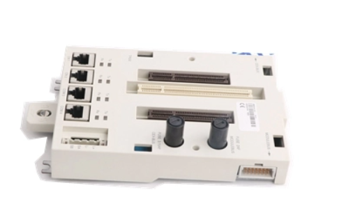
ABB TP830-1 PLC module

ABB TP830-1 is an excellent PLC module that plays an important role in industrial automation control systems, providing reliable control solutions for various complex industrial scenarios.

Functional Features

Digital input/output function: With 16 channels, it can be used as a digital output module to provide accurate digital control signals for industrial automation systems; It can also serve as a digital input module to receive digital signals from external devices, enabling monitoring and control of industrial processes.

Multi interface design: Equipped with multiple interfaces such as digital input, digital output, analog input, analog output, etc., it can easily connect and communicate with various sensors, actuators, and other devices to meet the diverse needs of different industrial scenarios.

High performance processing capability: Equipped with a high-performance processor, it has fast data calculation and processing speed, and can easily handle complex control algorithms and data processing tasks, ensuring the efficient operation of the system.

Real time monitoring and control: It can monitor and control various industrial processes and equipment in real time, detect and handle abnormal situations in a timely manner, achieve automation control and optimization, and improve production efficiency and product quality.

Reliability and Stability: Using high-quality materials and advanced manufacturing processes, it has undergone rigorous testing and inspection to adapt to different working environment temperature and humidity conditions. It can work stably in the temperature range of -25 ℃ to+60 ℃, with high stability and reliability, and can operate stably for a long time in harsh industrial environments.

Scalability: Supports combination and expansion with other devices, and supports multiple different communication protocols and control methods, making it convenient for users to flexibly integrate and control the system according to actual needs to meet constantly changing production requirements.

Easy to use: Supports plug and play, easy installation, and has a simple and easy to understand interface and operation interface, reducing the user’s threshold for use, reducing installation and debugging time, and facilitating maintenance and management.

Application area 

Manufacturing industry: Used for equipment control on production lines, such as robot control, automated assembly, material conveying, etc., to achieve automation and intelligence of the production process, improve production efficiency and product quality.

Process control: In process control systems in industries such as chemical, petroleum, and power, precise control of process parameters such as temperature, pressure, flow rate, and liquid level is carried out to ensure stable operation of the production process and consistency in product quality.

Factory automation: It can be used for the overall automation control system of factories, including workshop lighting control, air conditioning system control, access control system control, etc., to achieve intelligent management of factory facilities, improve the operational efficiency and management level of factories.

Install

Site Planning

Site selection and building requirements: The AC 800M system is designed for harsh industrial environments, introducing requirements for temperature, vibration, cooling, grounding, and other aspects, as well as other requirements such as room lighting independent of equipment power supply, complete process connections, effective grounding, cable wiring that complies with standard installation regulations, available power and other necessary facilities, compliance with standards and laws and regulations, and sufficient space in front of cabinets.

Cable: Introduces the requirements for laying on-site and communication cables, such as maintaining a distance of 10cm (4 inches) from other cables for short distance communication cables, maintaining a distance of 30cm (12 inches) from all power cables connected to AC 800M, and maintaining a distance of 10cm (4 inches) from relevant international immunity standard Category 4 cables; Applications that use shielded cables and situations where unshielded cables can be used; The lightning protection requirements for industrial equipment and power plants, as well as the installation of lightning protection equipment for overhead signal cable laying in large dispersed factories.

Power supply: Under normal circumstances, the power required for the AC 800M controller and related on-site equipment can be obtained from the factory’s standard 120/230V AC main power supply; When using the SD831/832/833/834 power unit, there is no need to use a main grid filter; The main circuit breaker must be installed near the controller installation to immediately and completely disconnect the power supply of the equipment when needed, and installed in an easily accessible and clearly visible location; Equipment connected to 115/230V AC power supply must be equipped with protective grounding (PE); To meet the requirements of IEC61131-2 for PE connection, it is recommended to use 35mm ² (2 AWG) copper wire as the PE conductor for the equipment; Recommended external main power supply fuse rating for standard AC 800M controller configuration, etc; The SD83X series power supply unit can easily handle short-term (<20 milliseconds) power outages that may occur in industrial environments, but to protect certain applications from transient voltage faults, uninterruptible power supply (UPS) equipment needs to be installed; The AC 800M controller will safely shut down in the event of a power failure, during which the application program memory and system clock are backed up by internal batteries. For systems that have not been running for a long time, it is recommended to install an external battery backup unit. After reconnecting to the power supply, the controller will restart and run the application program normally. If unexpected shutdown is not acceptable, it is strongly recommended to fully connect the AC 800M controller to an uninterruptible power supply (UPS) source.

Shell: The protection level of AC 800M and S800 I/O units is IP20, and each unit is individually marked with CE. If a higher IP level is required, an additional shell is needed; The use of additional enclosures usually does not affect the EMC characteristics of the controller; When installing the controller casing, in order to ensure good ventilation, a certain minimum distance should be maintained between the casing and the walls and ceilings; If the enclosure has a removable wall panel, it shall not be removed from any enclosure adjacent to any device that does not belong to the AC 800M controller and its connected S800 I/O; ABB recommends using RM550 (floor standing cabinet) and RE820 (wall mounted cabinet), with a protection level of IP54 and no additional cooling equipment required.

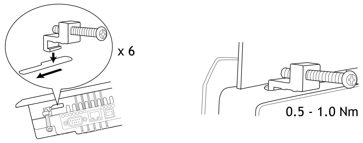
AC 800M unit installed on DIN rail: Due to the natural convection cooling of the AC 800M unit (CPU and communication interface), it can only be installed on a horizontal DIN rail; Each base has a locking mechanism that contacts the DIN rail with the metal backplate, providing an effective grounding connection. The DIN rail serves as the effective grounding for the system; The additional screw ears at the bottom of the base have no electrical function and can be used for additional fastening in environments with excessive vibration; There are two installation methods for the product in the cabinet, namely aluminum profiles with DIN rails or DIN rails installed on appropriately sized metal plates. The aluminum profiles or metal plates should be correctly connected to the protective grounding; Use DIN rails with a height of 7.5mm, referring to the NS 35/7.5 type of EN50022 standard; The interference suppression of external signals is usually directly grounded to the chassis and/or factory grounding, and the factory grounding potential must be stable and clear; The conductive backplate of each module is connected to a metal DIN rail as an electronic grounding conductor between modules, ensuring good grounding connection for internal logic, module EMI immunity, and RF transmission. The DIN mounting rail must have a good connection with the PE of the cabinet; If the AC 800M module is configured as two or more groups interconnected through extension cables, special attention should be paid to ensuring that all groups have good grounding connections for their DIN rails.

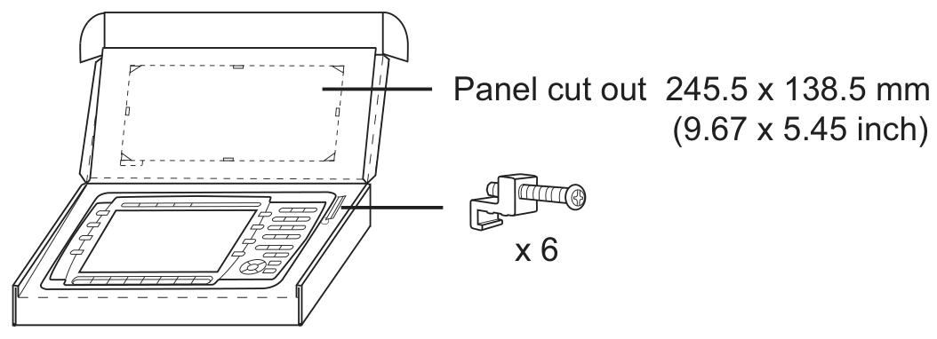
Other installation contents: including specific requirements and steps for installation on metal plates, installation of prefabricated aluminum profiles, as well as various processor units CEX-Bus、 The installation steps and precautions for communication interfaces, power supplies, main circuit breaker units, voting units, external battery units, I/O units, etc., as well as examples of installation in cabinets and installation size requirements for appropriate ventilation.

Configuration

General information: Using the engineering tool Control Builder, hardware (I/O and communication units) can be configured and applications can be created using control languages that comply with IEC 61131-3. The program can be compiled and run offline to facilitate process simulation before ultimately downloading the application to the controller. Control Builder provides a set of options, each with its own set of properties, simply select the option that is closest to the system requirements.

Connect Control Builder: Control Builder is installed on a PC and is usually connected to the AC 800M controller through the CN1 or CN2 ports on the control network and controller. It can also be connected through the COM4 port (RS-232C) on the AC 800M controller using tool cable TK212 and the serial port on the PC. In redundant configuration, Control Builder is connected to the COM4 port of the main CPU, and the backup CPU cannot communicate with Control Builder. PM851/PM851A is limited to one Ethernet (CN1) port and therefore does not support redundant Ethernet. The Control Builder standard does not support CI862, and to use CI862, appropriate system extensions must be installed. To use the FF HI function, the firmware of CI852 unit needs to be upgraded through the Serial Firmware Upgrade Tool. This tool loads special firmware with FF HI function into the controller and manually browses it in the Serial Firmware Upgrade Tool . \ Firmware Files \ SC860rFFHI folder and select firmware. ext.

Connecting to the control network: The control network is a dedicated IP network domain used for real-time data and general system communication between industrial computers, which can be expanded from small networks to large networks containing multiple “network areas” and hundreds of nodes. The controller is installed in the cabinet, and in industrial environments, AC 800M/control network connections must be converted to fiber optic (FO), which can be achieved by installing Ethernet switches with optical and electrical ports.

Communication possibility: The processor unit (PM8XX/TP830 or PM891) contains multiple communication ports, such as CN1 and CN2 for connecting to the control network, COM3 for RJ45 port with modem signal, COM4 for connecting to service tools, etc. By adding communication interfaces to CEX Bus, the number of protocols and processor unit ports can be expanded. The document lists the available interfaces and their quantities on CEX Bus.

Controller IP Address: It is recommended to always use the “Factory Reset” command to start an IPConfig session before allocating the expected IP address, in order to clear previously stored backup MAC and IP addresses (if any). Introduced the methods and precautions for setting IP addresses in both single CPU and redundant CPU configurations.

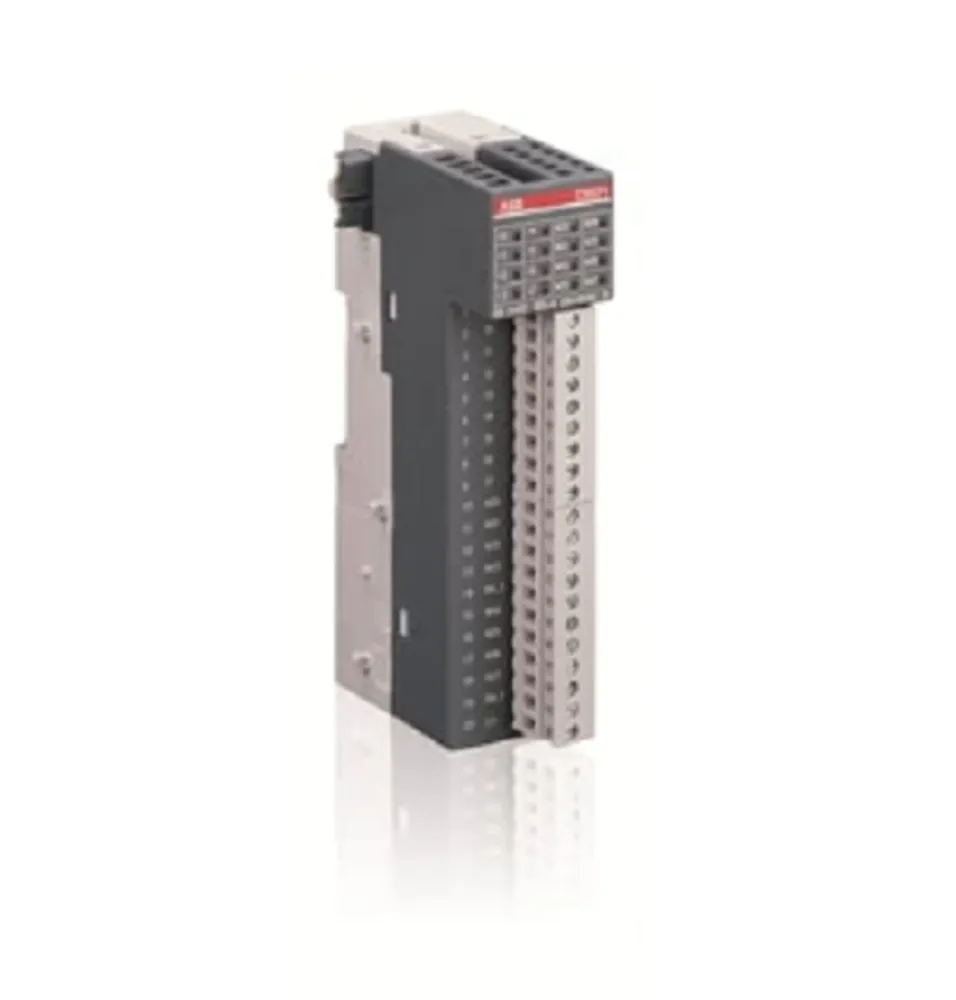
I/O system: There are various methods to connect the I/O system to the AC 800M controller, such as connecting S100 I/O through CI856; By connecting S800 I/O units through Modulus Bus, it supports hot configuration, redundancy at all levels, HART routing, and sequence of events (SOE) during operation. Also introduced ModuleBus、PROFIBUS DP、PROFINET IO、FOUNDATION Fieldbus High Speed Ethernet(FF HSE)、TRIO/Genius Remote I/O、Satt I/O on ControlNet、PROFINET IO via CI871  Waiting for relevant information.

Drive system: ABB standard (Std) and engineering (Eng) drives can be connected to AC 800M in various ways, such as optical Modulus Bus, CI801 and PROFIBUS DP, NPBA-12, RPBA-01 or FPBA-01 PROFIBUS DP adapter modules, and CI854. The relevant parameters and limitations of different connection methods are also introduced.

Power System: The power system configuration of the AC 800M controller is very simple, providing a series of simple circuit diagrams that demonstrate various possibilities of connecting the input main power supply to the 24V DC distribution terminal through the main circuit breaker, power unit, and SS83X voting device. It also introduces the requirements and precautions for power supply to units inside the cabinet, power supply to on-site equipment outside the cabinet, and power supply from external power sources.

Operate

AC 800M Controller (PM8xx): After being equipped with control software, the basic PM8xx/TP830 or PM891 hardware units installed on the AC 800M hardware platform constitute the AC 800M controller. Introduced relevant information on LED indicator lights, switches and buttons, and connectors.

Startup: including reference documents for firmware download, controller IP address, application download, firmware update, and other information; Precautions for CEX bus and CEX module during startup in redundant configuration.

Startup mode: including hot start, cold start, controller reset, and the operation methods and characteristics of cold start and controller reset in redundant configurations.

​ABB CP430 Human Machine Interface (HMI)

Operation Equipment

Basic features: CP430 is a human-machine interface (HMI) equipped with a 5.7-inch STN LCD display, with IP65/NEMA4X protection level (indoor use only), CE certification, strong transient resistance, compact design, and easy connection with other devices for optimal performance.

Configuration tool: Use CP400Soft for application design, which is reliable, easy to use, and compatible with multiple models.

Safety precautions

Personnel Qualification: Only qualified personnel are allowed to install, operate, or maintain the equipment.

Installation environment: It needs to be installed on a flat surface, and the environment should meet the requirements of no high explosion risk, no strong magnetic field, no direct sunlight, and no drastic temperature changes. It is suitable for pollution level 2 environment and can be installed on the flat surface of Class 1 and Class 4X (indoor only) enclosures.

Power requirements: The input is 24V DC, and the power supply voltage needs to be within the range of 24V DC ± 15%, otherwise it may seriously damage the equipment, and the power supply needs to be checked regularly.

Grounding requirements: The grounding cable must be correctly grounded, otherwise it may be affected by noise. The cross-sectional area of the grounding cable should be at least 2mm ² (AWG 14), the grounding resistance should be less than 100 Ω (level 3), and the grounding cable must not be connected to the same grounding point as the power circuit.

Other precautions: Do not allow liquids, metal debris, etc. to enter the equipment; LCD display screens contain highly irritating substances in liquid, and contact with the skin or eyes requires timely treatment; ABB is not responsible for equipment modification or the use of non ABB specification components and accessories; Communication cables should be separated from power cables and only shielded cables should be used.

Installation instructions

Packaging content

Includes CP430 operator terminal, 6 installation fasteners, power connector (connected to 24V DC power input), and installation and operation manual (1SBC159103M0202).

Installation steps

Drill holes on the control front panel according to the dimensions of 185.8 × 135.8mm.

Install the operator terminal into the opening, insert the fixture into the hole on the device, and tighten it to the front panel with screws, with a torque of 0.6~0.7 Nm (5.31-6.2 lb in).

The installation angle of the operator terminal should be within the range of 0 ° to 135 °.

Product specifications

General parameters (some main parameters)

Front panel size: 195.0 × 145.0 × 6.0mm.

Installation depth: 59.1mm.

Weight: ranging from 0.81 to 0.86kg.

Communication ports: COM1 (9-pin female connector, supporting RS232/RS485), some models have COM2 (25 pin female connector, supporting RS232/RS422/RS485); Some models have USB ports, CF card ports, and Ethernet ports.

Storage: 4MB Flash ROM, 16MB RAM, 512KB battery backup memory, 512KB data/recipe.

Display screen: Color TFT LCD (some models are monochrome STN LCD), 64K colors (some models are 16 blue tones), resolution of 320 × 240 pixels, CCFT backlight lifespan of approximately 50000-60000 hours at 25 ° C.

Power supply: 24V DC ± 15%, power consumption less than 20W.

Working environment: Temperature range of 0 ° C to+50 ° C, humidity range of 20-90% RH (non condensing).

Operating instructions

DIP switch settings

SW1, SW2, and SW9 are reserved.

SW3 and SW4 are used to set operating modes, such as running user applications, running aging test programs, etc.

SW5 is used to select the source of communication parameters, either from the operator terminal configuration screen or CP400Soft.

SW6 is used to set whether a password is required to start the operator terminal.

SW7 is used to set whether to display the system menu.

SW8 is used to set the default user level.

SW10 is used to set the COM2 port type (RS485 or RS4)

ABB 81EU01-E/R3210 Analog Signal Input Module

Module Overview

Application scenario: As an alternative to multiple input modules, it is suitable for 2-wire transmitters (4… 20mA, module power supply), 4-wire transmitters (0/4… 20mA, module or external power supply), and can replace 81EA01-E/R1010 (without calibration function), 81EA01-E/R1111 (with calibration function, no raw value output), and 81EA01-E/R1112 (with calibration function, raw value output).

Core functions: Includes 5 functional units, each unit can flexibly configure input modes, supports parameter programming (stored in EEPROM, not lost during power failure); Each analog signal can be assigned up to 4 limit values and supports 5 independent correction or filtering calculations (implemented through functional blocks).

Main characteristics

Interface and Communication: Equipped with PROCONTOL station bus standard interface, signals are transmitted in the form of telegrams. Before sending, a test flag is verified and marked, and when receiving, transmission integrity is also verified based on the test flag.

Anti interference design: It can eliminate interference between functional units and station buses, and each functional unit is equipped with a short-circuit protection and monitoring transmitter power supply.

Status indication: The ST (universal interference) indicator light on the front panel can display the response of internal monitoring circuits or input signal monitoring.

Signal processing and monitoring

Analog signal input and conversion

The input current signal is converted into a measurement voltage on a high-precision measuring resistor, connected to the input instrument amplifier through a multiplexer, and then converted into a 12 bit digital analog signal through an A/D converter.

The input instrumentation amplifier and A/D converter are monitored through reference voltage, while the analog signal is monitored through flatness (default upper limit of 118.75%, lower limit of -6.25%, can be modified in the configuration list). If exceeded, a response is triggered.

Fault handling

If the input is overloaded due to a circuit fault, the relevant functional unit will immediately shut down, and a “Process channel fault” message will appear in the diagnostic register. The interference bit in the data telegram will be set, and every 30 seconds, an attempt will be made to reactivate the unit.

When receiving bus telegrams, periodic updates will be monitored. If the signal has not been updated for a long time (such as a sending module failure), the receiving monitoring function will set the interference bit in the corresponding register, continue to use the last received value to calculate and forward the result with the interference bit.

Correction and filtering functions

Function block support: Provides flow measurement correction (KOR1 for water/steam, KOR3 for variable reference pressure gas), liquid level measurement correction (NIV), nonlinear filtering (FIL), each functional unit can use one function block, and KOR1, KOR3, and NIV include FIL function.

Restrictions: Maximum of 5 functional blocks, maximum of 20 bus signals, and maximum of 1 functional block per functional unit; When using functional blocks, the module cycle time will increase the calculation time of the corresponding functional block.

Limit signals and events

Limit setting: Each functional unit can program up to 4 limit values, and each limit value can choose 4 hysteresis values (HY1=0.39%, HY2=1.56% default HY3=3.12%、HY4=6.25%), The limit range is -150% of the set signal range …+150%.

Event trigger: When exceeding the limit, monitoring function response, analog value change exceeds the adjustable threshold (0.2%… 6.8%, default 1.56%) and exceeds the adjustable time (40ms, 200ms default), a limit signal telegram will be immediately sent to the station bus.

Diagnosis and status indication

Local indication: The front-end ST indicator light displays all interference and data communication interference of the module.

Diagnostic register: Register 246 stores fault types, including parameter faults, process channel faults, checksum errors, fault handling, etc., which can be sent to the alarm system or control diagnostic system (CDS) through the bus.

Fault cause: Process channel faults may be caused by unreliable analog signals, internal reference value interference, transmitter monitoring response, etc; Handling faults may be caused by invalid configuration lists, internal voltage interference, hardware defects, etc.

GJR2391500R1210 ABB - 81EU01

ABB Panel 800- PP836 5.1 Hardware and Installation

Equipment Overview

Core function: Panel 800 operator panel is an industrial equipment designed for human-computer interaction, supporting functions such as text display and control, dynamic indication, time channel, alarm, and recipe management. After configuration is completed on the computer through the Panel Builder 800 configuration tool, the project can be transmitted to the panel and stored for operation. It can be connected to various automation devices such as PLC, servo system, and driver.

Version History:

Version 4.1: Initial release of Panel 800, firmware version 1.0, corresponding to document 3BSE043449R101.

Version 5.0: Firmware version 2.0, supports MMS alarms and events and PROFIBUS-DP slave interface (CB801), corresponding to document 3BSE043449R201.

Version 5.0/1: firmware version 3.0, corresponding to document 3BSE043449R301.

Version 5.1: Firmware version 4.0, corresponding to document 3BSE043449R401.

Version 5.1/3: PP836A is released, corresponding to document 3BSE043449R501.

Safety precautions

Installation environment: Suitable for Class I, Division 2, Groups A, B, C, D or non hazardous locations; When installed horizontally, the maximum ambient temperature is 40 ° C, and when installed vertically, it is 50 ° C. It is necessary to avoid high explosion risks, strong magnetic fields, direct sunlight, and drastic temperature changes.

Explosion proof warning: In explosive hazardous environments, power off or confirm the safety of the area before disconnecting the equipment; Replacing components may affect the applicability of Class I, Division 2 locations; Only allow connection to UL and cUL certified extension units (currently no approved units); Power off or confirm the safety of the area before replacing the expansion unit; The battery needs to be replaced in a non hazardous area.

Operation and maintenance: Only qualified personnel are allowed to operate, install, and repair; Check for transportation damage before installation; Prohibit liquids, metal debris, etc. from entering the equipment; Disconnect the power supply before cleaning or maintenance; Use recommended battery replacement to avoid the risk of explosion; Equipment and components need to be recycled according to local regulations, and lithium batteries, electrolytic capacitors, and displays contain potentially harmful substances.

Installation process

Space requirements

Installation plate thickness: 1.5-9.0 mm (0.06-0.35 inches).

Installation space: A certain amount of space should be reserved around the panel, such as 100 mm (4.0 inches) above and below, 50 mm (2.0 inches) on both sides, etc. The opening of the shell is for air convection and cannot be covered.

Installation steps

Unpacking inspection, notify the supplier if there is any damage; The panel opening size is 245.5 x 138.5 mm (9.67 x 5.45 inches).

Determine the installation position of the panel, cut the opening according to the markings, and reserve additional space in the lower left corner if accessing the text bar is required.

Use all fastening holes, provided brackets, and screws to secure the panel with a torque of 0.5-1.0 Nm.

Connect the cables in the specified order, ensuring that the panel and controller system are grounded consistently. Use M5 screws and a grounding wire with a minimum cross-sectional area of 2.5 mm ² (as short as possible); Use shielded communication cables to separate high-voltage cables from signal and power cables; The panel needs to adapt to the ambient temperature before starting to avoid condensation, and confirm that the power supply voltage and polarity are correct.

Be careful to remove the laminated film on the panel display screen to avoid electrostatic damage.

Mode switch setting

There are 4 DIP switches (mode switches) on the back of the panel. Before operation, the power needs to be disconnected, and after setting, it needs to be reconnected.

The functions are as follows:

0000: Operating mode, normal operation.

0010: System recovery, resetting file system and registry, reinstalling system programs, restoring factory settings (may overwrite updated system programs, can be updated again).

0100: Mirror loading mode, allowing upgrading of complete software packages in the panel (deleting all files).

1000: Service menu mode, displaying system program service menu, can set IP configuration, delete items, calibrate touch screen.

1110: Self check mode.

Xxx1: Hard reset (forced panel reset).

ABB PM866AK01 Controller

Equipment Overview

Core function: PM866AK01 is a compact processor unit of ABB AC 800M series, with control, communication, and redundancy support capabilities, suitable for industrial automation control scenarios, and can be configured through 800xA Control Builder.

Hardware composition: including microprocessor, RAM memory, real-time clock, LED indicator lights, Initiat button, and CompactFlash interface; The base (TP830) is equipped with 2 RJ45 Ethernet ports (CN1, CN2) and 2 RJ45 serial ports (COM3, COM4), where COM3 is the RS-232C port with modem control signal and COM4 is the isolated configuration tool port.

Key features: Supports CPU redundancy (improves availability, covers CPU, CEX Bus, communication interfaces, and S800 I/O), DIN rail quick installation (sliding locking mechanism), each base has a unique Ethernet address (hardware identity identification, can be viewed on the TP830 base label).

Core advantages

Having ISA Secure certification, high reliability, and easy fault diagnosis.

Modular design, supporting gradual expansion and adapting to applications of different scales.

The protection level is IP20 and no additional casing is required; Obtained comprehensive EMC certification.

Support the use of BC810/BC820 to implement segmented CEX Bus, ensuring communication compatibility based on standard hardware such as Ethernet, PROFIBUS DP, etc.

Built in redundant Ethernet communication ports to enhance communication stability.

Technical Parameter

Basic information

Product Code: 3BSE076939R1 (PM866AK01)

Redundancy support: None

High integrity: None

Clock frequency: 133 MHz

Performance (1000 Boolean operations): 0.09 ms

Memory 64 MB: (Application available RAM: 51.389 MB)

Storage flash memory:; support

Processor type: MPC866

Redundant configuration switching time: maximum 10 ms

Software and Task Capability

Each controller supports 32 applications, and each application supports 64 programs and 128 charts.

The controller supports up to 32 tasks with 32 different cycle times, and the application cycle time can be as low as 1 ms.

The firmware storage flash is 4 MB.

Power supply and power consumption

Power input: 24 V DC (19.2-30 V DC).

24V current consumption: typical 210 mA, maximum 360 mA.

Power consumption: Typical 5.1 W, maximum 8.6 W.

Supports redundant power status input and built-in 3.6V lithium battery backup.

​Communication and I/O capability

Ethernet channels: 2 (IEEE 802.3 standard, 10 Mbit/s, RJ-45 female head)

Control network protocols: MMS (Manufacturing Message Service) and IAC (Inter Application Communication)

Recommended Control Network Backbone: 100 Mbit/s Switched Ethernet

Two RS-232C interfaces: (one universal and one for service tools)

Number of CEX Bus communication modules: 12

CEX Bus maximum power supply current: 2.4 A

Modulabus I/O cluster with non redundant CPUs: 1 electrical+7 optical

Modular I/O cluster with redundant CPUs: 0 electrical+7 optical

Maximum I/O module capacity of Modulabus: 96 for a single PM866 and 84 for redundant PM866

Modulus scan rate: 0-100 ms (depending on the number of I/O modules)

ABB TK850V007 CEX Bus expansion cable Installation

Preparation before installation

Check product integrity: Confirm that the length of the TK850V007 expansion cable is 0.7 meters and that the matching CEX Bus terminator TK851 is intact and undamaged.

Tool preparation: Prepare a suitable screwdriver (for operating the DIN rail locking device) and insulated gloves (to ensure safe operation).

Environmental requirements: Ensure that the installation environment meets the working environment standards of the AC 800M controller, with a temperature between -25 ° C and+55 ° C and a relative humidity of<93% (no condensation).

Installation steps

Power off operation

Before installation, the power supply of the AC 800M controller and related equipment must be disconnected to avoid electric shock or equipment damage.

Positioning installation location

Determine the connection location of the CEX Bus expansion cable, typically used to connect two CEX Bus segments or extend the length of the CEX Bus. Ensure that the cable path is not stretched or excessively bent, and avoid approaching strong electromagnetic interference sources such as motors and transformers.

Connecting cables

Connect one end of the cable to the output port of the existing CEX Bus device and the other end to the input port of the expansion device, ensuring that the plug is fully inserted and locked.

If used to connect two CEX Bus network segments, terminal TK851 (female end) should be installed at both ends of the cable to ensure signal stability.

Fixed cable

Use cable ties or clamps to secure cables to DIN rails or cabinets, avoiding loose connections caused by vibration.

power restoration

After confirming that all connections are correct, reconnect the power and check the operating status of the CEX Bus device (using LED indicator lights to determine if it is working properly).

Configuration points

Terminal settings

When using the TK850V007 expansion cable, a TK851 terminator must be installed at the female end of the cable to prevent signal reflection and interference.

If the extension cable is connected to a redundant CEX Bus structure, it is necessary to ensure that the terminal is correctly installed on both ends of the redundant network segment.

System Verification

After power on, check the CEX Bus communication status through the diagnostic function of the controller or the front panel indicator lights to ensure there are no error codes or alarm signals.

Use Control Builder software to verify whether the extended CEX Bus device is correctly recognized by the system, and confirm that the communication rate and data transmission are normal.

Redundant configuration (if applicable)

If used for redundant systems, CEX Bus redundancy parameters need to be configured in Control Builder to ensure uninterrupted data transmission when switching between primary and backup network segments.

Check the switching time and stability of redundant links to ensure compliance with system design requirements.

​Precautions

Cable length limit: The maximum length of TK850V007 is 0.7 meters and cannot be used in series with other extension cables to extend the length, otherwise it will cause signal attenuation.

Avoid ignition limit: The network segment configuration after CEX Bus expansion must not be within the ignition limit range of the device, and safety parameters in the device manual should be referred to.

Hot swappable restriction: Cables cannot be plugged or unplugged while live, and must be operated with power off, otherwise it may cause equipment damage or data loss.

Grounding requirements: Ensure that the cable shielding layer is properly grounded to reduce electromagnetic interference and improve communication stability.

Buy ABB TK850V007 3BSC950192R1 CEX-Bus Extension Cable,ABB TK850V007 ...

ABB AO801 Analog Output Module

Equipment Overview

Core function: AO801 is ABB Ability ™  System 800xA ®  The series of analog output modules has 8 unipolar analog output channels, which can perform self diagnosis periodically. When the internal power supply is too low, the module will enter the Initiat state (at this time, the module has no signal output).

Main features and advantages:

It has 8 output channels of 0… 20 mA and 4… 20 mA.

Equipped with OSP (Output Switching Protection) function, it can set the output to the preset state when an error is detected.

The analog output has short-circuit protection function and can be connected to ZP or+24 V.

Process and power connections are achieved through detachable connectors.

Basic information

Product Code: 3BSE020514R1

Type: Analog Output Module

Signal specifications: 0… 20 mA, 4… 20 mA

Number of channels: 8

Signal type: unipolar single ended

HART protocol support: not supported

SOE (Sequence of Events): Not supported

Redundant function: not supported

High integrity: not supported

Intrinsic safety: not supported

Mechanical specification: S800L

Technical Parameter

Resolution: 12 bits

Isolation method: Group level and ground isolation

Range of over/under range: ± 15%

Output load: Maximum 850 Ω

Error: 0.1%

Temperature drift: typical 30 ppm/° C, maximum 50 ppm/° C

Rise time: 10 µ s

Update cycle: 1 ms

Current limit: limited current output with short-circuit protection

Maximum on-site cable length: 600 meters (656 yards)

Rated insulation voltage: 50 V

Dielectric test voltage: 500 V AC

Power consumption: 3.8 W

+Bus current consumption of 5V module: 70 mA

+Bus current consumption of 24V module: none (-)

+24V external current consumption: 200 mA

Supported wire specifications: Solid wire: 0.05-2.5 mm ² (30-12 AWG); Stranded wire: 0.05-1.5 mm ² (30-12 AWG). Recommended torque: 0.5-0.6 Nm, wire stripping length: 6-7.5 mm (0.24-0.30 inches)

Diagnosis and indicator lights

Front panel indicator light: equipped with S (Status) indicator light, used to display operation or fault status, can indicate monitoring status, module errors, module warnings, channel errors and other information.

Environment and Certification

CE mark: Yes

Electrical safety standards: EN 61010-1, UL 61010-1, EN 61010-2-201, UL 61010-2-201

Dangerous Place Certification: C1 Div 2 cULus, C1 Zone 2 cULus, ATEX Zone 2

Classification Society Certification: ABS, BV, DNV, LR

Operating temperature: 0 to+55 ° C (+32 to+131 ° F), certified for+5 to+55 ° C

Storage temperature: -40 to+70 ° C (-40 to+158 ° F)

Pollution level: Level 2 (compliant with IEC 60664-1)

Corrosion protection: Complies with ISA-S71.04: G3 standard

Relative humidity: 5% to 95% (without condensation)

Protection level: IP20 in accordance with IEC 60529

Mechanical working conditions: comply with IEC/EN 61131-2

Electromagnetic compatibility: compliant with EN 61000-6-4 and EN 61000-6-2

Overvoltage category: Complies with IEC/EN 60664-1, EN 50178

Equipment category: Class I (grounding protection) in accordance with IEC 61140

RoHS compliance: Compliant with Directive 2011/65/EU (EN 50581:2012)

WEEE Compliance: Compliant with Directive/2012/19/EU

Size and weight

Width: 86.1 mm (3.4 inches)

Depth: 58.5 mm (2.3 inches)

Height: 110 mm (4.33 inches)

Weight: 0.24 kg (0.53 lbs.)

ABB CI855 communication interface

Equipment Overview

Core function: CI855 is a communication interface used to implement the MasterBus 300 (MB300) communication protocol in AC 800M controllers. This protocol is suitable for communication between controllers and operator stations in devices based on Advant OCS and equipped with Master software. It is connected to the CEX bus through the backplane.

Supporting components: The TP853 motherboard is equipped with RJ45 connectors with two Ethernet ports, supporting network redundancy and providing a convenient DIN rail installation method.

Key advantage: Supports peer-to-peer communication between new factory areas using AC 800M controllers and existing controllers based on MB300, such as Advance Controller 410, Advance Controller 450, MasterPiece 200/1, etc.

Basic information

Product Code: 3BSE018106R1

Communication protocol: ABB’s MasterBus 300

Master slave attribute: Master device

Transmission speed: 10 Mbit/s, 200 datasets/second

Line redundancy: supported

Module redundancy: not supported

Hot swappable: Supports

Used in conjunction with HI controller: Supports

CE certification: Yes

Classification Society Certification: BV, DNV-GL, LR

RoHS compliance: Compliant with Directive 2011/65/EU (EN 50581:2012)

WEEE Compliance: Compliant with Directive/2012/19/EU

Detailed parameters

Maximum number of units on CEX bus: 12

Connector: RJ-45 female head (8-pin)

24V power consumption (typical value): 150 mA

Environment and Certification

Working temperature:+5 to+55 ° C (+41 to+131 ° F)

Storage temperature: -40 to+70 ° C (-40 to+158 ° F)

Corrosion protection: Complies with the G3 standard of ISA 71.04

Protection level: IP20 compliant with EN60529 and IEC 529

Size and weight

Width: 59 mm (2.3 in.)

Height: 185 mm (7.3 in.)

Depth: 127.5 mm (5.0 in.)

Weight (including base): 700 g (1.5 lbs)

Functional Features

Convenient selection and comparison: It allows users to quickly browse and select suitable hardware devices, while also being able to compare different hardware options, making it easier for users to make decisions based on their own needs.

Flexible filtering: supports filtering based on various conditions, such as functional requirements, performance indicators, application scenarios, etc., to help users accurately locate the desired product from numerous Compact Product Suite hardware products.

Data download: Users can download PDF overview files for specific product areas, as well as export detailed data tables for individual products for reference and analysis during the selection process.

Association with CI855

Communication function matching: ABB CI855 is a high-performance communication interface module suitable for industrial automation systems, supporting communication protocols such as Ethernet/IP and Modbus TCP/IP. Hardware selectors can help users select other hardware devices that match the communication protocol, data transmission rate, and other aspects of CI855, ensuring smooth data interaction throughout the system.

Environmental adaptability coordination: CI855 can operate reliably in an environment with a temperature range of -25 ° C to+60 ° C and humidity up to 95%. Through hardware selectors, other hardware that can work stably under the same or similar environmental conditions can be selected to ensure the overall stability of the system in harsh industrial environments.

I/O configuration collaboration: The CI855 module has up to 8 configurable input/output channels. Hardware selectors can assist users in selecting other devices that can work together with them in terms of I/O points, types, etc., to achieve optimized configuration of system input and output functions.

ABB REF615R feeder protection and control

Equipment Overview

Core function: REF615R is a dedicated intelligent electronic device (IED) for feeder lines, designed specifically for the protection, control, measurement, and monitoring of utility substations and industrial power systems. It is an ABB Relion ®  Part of the 615 series products adopts a compact and withdrawable design.

Unique features

Provide four major replacement conveniences for ANSI and IEC DPU2000R users: the same appearance and size, no need to cut panels or reposition racks; I/O and CT/VT connections similar to wiring greatly reduce drawing modification time; Has considerable protection and control functions, and includes more functions; Close to SCADA compatibility in terms of DNP 3.0 points and Modbus registers.

Other features: six setting groups, pull-out design, optional underground and overhead cable fault detection (CFD), optional high-speed (<1 ms) output, on-site selection of 1A or 5A CT input, advanced user programmable function block, 16 programmable buttons, etc.

Standard configuration

Main applications: feeder protection and control, providing a standard configuration whose relay functions and characteristics are based on the analog inputs ordered for that configuration.

Configuration A: Directional phase and ground overcurrent, voltage and frequency protection, synchronous inspection, control, and power system metering (for one circuit breaker).

Compatible configuration: It can meet and exceed DPU2000R ANSI and IEC configurations, such as standard type, synchronous check type, SEF type, etc.

Protection function

Main protection functions: Provides protection against non directional phase and ground overcurrent, phase step distance, thermal overload, phase imbalance, and phase discontinuity, with sensitive ground fault (SEF), high impedance fault detection (HIZ), directional phase, ground, and neutral overcurrent, as well as phase, ground (residual), positive and negative sequence undervoltage and overvoltage protection.

Other protection functions: Provide three pole multiple automatic reclosing function for overhead distribution feeders of public utilities; Enhanced Arc Flash Detection (AFD), with three light detection channels, is used to detect arc faults in cable compartments of circuit breakers, busbars, and metal enclosed switchgear.

Application scenarios

Provide DPU2000R users with an economical and convenient solution for upgrading and replacing existing ANSI or IEC DPU2000R relays, without the need to change drawings, cut or replace wiring harnesses, cut metal, or add adapter plates.

Suitable for new users looking for the 19 inch rack installation form of ABB Relion 615 series.

Can be applied to various protection, control, and metering scenarios, supporting comprehensive utility and industrial distribution feeder solutions.

Supported ABB solutions

Together with the COM600 grid automation controller, it forms a true IEC 61850 solution for reliable distribution in utility and industrial power systems.

Provide a connection package that includes software and IED specific information, facilitating configuration through PCM600 protection and control of the IED manager, and integrating with COM600 station automation equipment or MicroSCADA Pro network control and management system.

Supports connection with systems such as MicroSCADA Pro and System 800xA.

Control, measurement, and recording functions

Control function: Provide the status and control of a circuit breaker through a set of buttons on the local human-machine interface (LHMI) on the front panel, support remote circuit breaker control, and configure interlocking schemes through the signal matrix tool in PCM600.

Measurement function: Continuously measure phase current and voltage, sequence components and residual current, calculate demand and minimum/maximum demand current, thermal overload of protected objects, phase imbalance values, etc. It can also measure voltage, power and energy, etc.

Recording function: including digital fault recorder (DFR), event sequence recorder (SER), which can store fault records, demand and minimum/maximum demand current data, and has load curve recording function.

Monitoring and diagnostic functions

Circuit breaker status monitoring: including checking the wear and tear of the circuit breaker, the spring charging time of the circuit breaker operating mechanism, the gas pressure in the circuit breaker chamber, etc., monitoring the action time and operation frequency of the circuit breaker.

Trip circuit monitoring: Continuously monitor the availability and operability of the trip circuit, and detect the loss of circuit breaker control voltage.

Self diagnosis: The built-in self diagnostic system continuously monitors the hardware status and software operation of the relay. When a fault or malfunction is detected, it will alert the operator. Permanent relay faults will prevent the protection function of the relay.

Other monitoring functions: fuse fault protection, current circuit monitoring, etc.

Input/Output and Communication

input/output

Analog inputs: including current (CT) and voltage (VT) analog inputs, phase current inputs can be programmed by users to 5A or 1A CT secondary ratings, etc.

Binary Input/Output: The threshold for opening binary input can be programmed by adjusting the parameters of the relay, and all binary input and output contacts can be freely programmed using the signal matrix tool in PCM600 software.

Communication function: Supports multiple communication protocols, including IEC 61850, Modbus ®  And DNP3.0 Level 2+; Provide multiple communication interface options, such as Ethernet interface, serial interface, etc; Support multiple time synchronization methods.

Technical data

Physical characteristics: Width 19.0 inches (482.6 mm), height 5.22 inches (132.6 mm), depth 9.08 inches (230.66 mm), unpacked weight 11.9 pounds (5.4 kg), boxed weight 16.4 pounds (7.44 kg).

Power supply: There are two types of power supplies, with different input voltage ranges and power consumption.

Environmental conditions: working temperature range -25 ° C to+55 ° C, short-term working temperature range -40 ° C to+85 ° C (<16 hours), relative humidity<93% (non condensing), etc.

Electromagnetic compatibility: Passed multiple electromagnetic compatibility tests and meets relevant standards.

Installation and Accessories

Installation methods: rack mounted, semi embedded, and panel mounted. Rack mounted installation requires ordering installation kits.

Accessories: including tools (such as PCM600 V2.5 user tools), cables (such as optical sensor cables for arc protection), installation accessories (such as panel mounting frame/cover kit), spare parts, etc.

ABB EL3020 Model EasyLine Continuous Gas Analyzers

Equipment Overview

Core function: EL3020 is a multi-component continuous gas analyzer that can simultaneously measure up to 5 gas components, suitable for various process and emission monitoring scenarios, and supports flammable gas measurement.

Core features: Equipped with automatic calibration function (including pump and valve control), it can simplify calibration through air or built-in calibration units, without the need to test gas cylinders; Provide customizable analog outputs, digital inputs/outputs, and Modbus interfaces; Adopting a modular design, it is easy to maintain and has self-monitoring function, which can prompt maintenance needs.

Shell design: 19 inch rack mounted shell (3 height units) with a protection level of IP20.

Measurement technology (analyzer)

Uras26 infrared photometer

Measurement object: Infrared active gas components such as CO, NO, SO ₂, etc.

Measurement range: adjustable between 0-500ppm (NO 750ppm), 0-1000ppm, 0-3000ppm, and 0-1Vol. -% to 0-100Vol. -%, with a maximum range ratio of 1:5. Specific ranges can be set according to factory requirements, but the range should not be set within the ignition limit.

Performance indicators: Linear deviation ≤ 1% range; Repeatability ≤ 0.5% range; Zero drift ≤ 1% range/week; Sensitivity drift ≤ 1% measured value/week; Output fluctuation (2 σ) ≤ 0.2% range; Detection limit (4 σ) ≤ 0.4% range.

Influencing factors: Flow rate within the range of 20-100l/h affects within the detection limit; The impact of environmental temperature changes on zero point is ≤ 2% of the range/10 ° C, and on sensitivity (without a thermostat) is ≤ 3% of the measured value/10 ° C. If a thermostat is installed (55 ° C), the impact is ≤ 2% of the measured value/10 ° C. After calibration by a pressure sensor, the impact of pressure changes on sensitivity is ≤ 0.2% of the measured value/1% of the pressure change.

​Magnos206 Oxygen Analyzer

Measurement object: O ₂ in process gas or nitrogen.

Measurement range: minimum range of 0-2Vol. -% O ₂, maximum range of 0-100Vol. -% O ₂, can be set to suppress zero point range (such as 98-100Vol. -% O ₂).

Performance indicators: Linear deviation ≤ 0.5% range; Repeatability ≤ 1% range; Zero drift ≤ 0.1Vol. -% O ₂/week; Sensitivity drift ≤ 0.1Vol. -% O ₂/week or ≤ 1% measured value/week (whichever is smaller); Output fluctuation (2 σ) ≤ 0.5% minimum range; Detection limit (4 σ) ≤ 1% minimum range.

Influencing factors: Flow rate within the range of 30-90l/h affects ≤ 0.1Vol. -% O ₂; Multiple associated gases have different effects on zero point; The impact of ambient temperature on zero point is ≤ 1% range/10 ° C (≤ 2% range/10 ° C when combined with Uras26), and the impact on sensitivity is ≤ 0.2% measured value/10 ° C. After correction, the impact of pressure changes is ≤ 0.01% measured value/1% pressure change or ≤ 0.002Vol. -% O ₂/1% pressure change (whichever is greater).

Caldos27 Thermal Conductivity Analyzer

Measurement object: Binary gas mixtures with different thermal conductivities, such as Ar in O ₂, H ₂ in Ar, CH ₄ in N ₂, etc.

Measurement range: There are different minimum ranges and ranges with zero suppression for different gas combinations, with a maximum range of 0-100Vol. -% or 0Vol. -% to saturation. The range can be freely adjusted within a given range, but should not be set within the ignition limit.

Performance indicators: Linear deviation ≤ 2% range; Repeatability ≤ 1% range; Zero drift ≤ 2%, minimum possible range/week; Sensitivity drift ≤ 0.5% minimum possible range/week; Output fluctuation (2 σ) ≤ 0.5% minimum range; Detection limit (4 σ) ≤ 1% minimum range.

Influencing factors: When the flow rate changes by 10l/h, it affects the range by ≤ 0.5%; The impact of environmental temperature changes is ≤ 1% range/10 ° C; the impact of air pressure changes on the minimum range is ≤ 0.25% range/10hPa, and the larger the range, the smaller the impact.

Electrochemical oxygen sensor

Measurement object: O ₂, and can only be used in combination with Uras26 infrared photometer.

Measurement range: adjustable from 0-5Vol. -% O ₂ to 0-25Vol. -% O ₂, with a minimum range of 0-5Vol. -% O ₂.

Performance indicators: Linear within the range of>1Vol. -% O ₂; Repeatability ≤ 0.5% range; Zero point long-term stability; Sensitivity drift ≤ 1% measurement range/week; Output fluctuation (2 σ) ≤ 0.2% measurement range; Detection limit (4 σ) ≤ 0.4% measurement range.

Influencing factors: Flow rate within the range of 20-100l/h affects ≤ 2% of the measurement range; The impact of changes in ambient temperature within the range of 5-40 ° C is ≤ 0.2Vol. -% O ₂/10 ° C; the impact of changes in air pressure without pressure correction is ≤ 1% of the measured value/1% of the air pressure change, and ≤ 0.2% of the measured value/1% of the air pressure change with correction (to be connected to Uras26 with pressure sensor).

Integrated gas feed (optional)

Version: A module that includes a microfilter and a flow sensor; Another type includes a microfilter, solenoid valve, pump, coarse filter, capillary tube, and flow sensor module.

Performance: The maximum feed rate of the pump is 60l/h (depending on the analyzer type and inlet/outlet pressure), and the flow rate is adjustable; The retention rate of the filter for particles larger than 0.1 μ m is 99.99%.

Restriction: Cannot be used for measuring flammable gases and flammable gas/air or gas/oxygen mixtures.

general data

Shell material: galvanized steel plate (painted on the outer surface), analyzer rear panel made of aluminum and PVC-C, keyboard board made of polyester, with colors of light gray (RAL 7035) and basalt gray (RAL 7012), weighing approximately 7-15kg.

Display and operation: Backlit graphic display screen (240 × 160 pixels), capable of displaying numerical values (with physical units and bar charts), up to 5 measurement values, and flow bar charts, with status display function; Use the 5 keys (cursor cross and OK) to perform menu assistance operations.

Power supply: 100-240V AC (-15%,+10%), 50-60Hz (± 3Hz), maximum power consumption of 187W, equipped with a 3-pin plug and a 2m long connecting cable.

Environmental conditions: working temperature of 5-45 ° C (5-40 ° C when combined with other analyzers), storage and transportation temperature of -25-65 ° C; relative humidity<75%, slight condensation allowed; When installing multiple enclosures in a 19 inch rack, at least one height unit should be separated to ensure sufficient air circulation.

Electrical and gas connections

Electrical connections: including power connections, I/O modules (analog output, digital input/output, RS232/RS485, etc.), Ethernet interfaces, etc., with a maximum terminal capacity of 1mm ² wires.

Gas connection: Different analyzers (Uras26, Magnos206, Caldos27) have different gas inlet and outlet designs, including two versions of hose connection (4mm inner diameter) and pipeline connection (1/8 NPT internal thread). The specific interface functions vary depending on the version and configuration.

authentication

Compliant with the EU Low Voltage Directive (73/23/EC) and EMC Directive (89/336/EC).

Obtained CSA certification in the United States and Canada, compliant with CAN/CSA-C22.2 No.61010-1-04/UL 61010-1:2004 (2nd edition) standards, suitable for general environments.

Search for products

Back to Top
Product has been added to your cart