Product overview
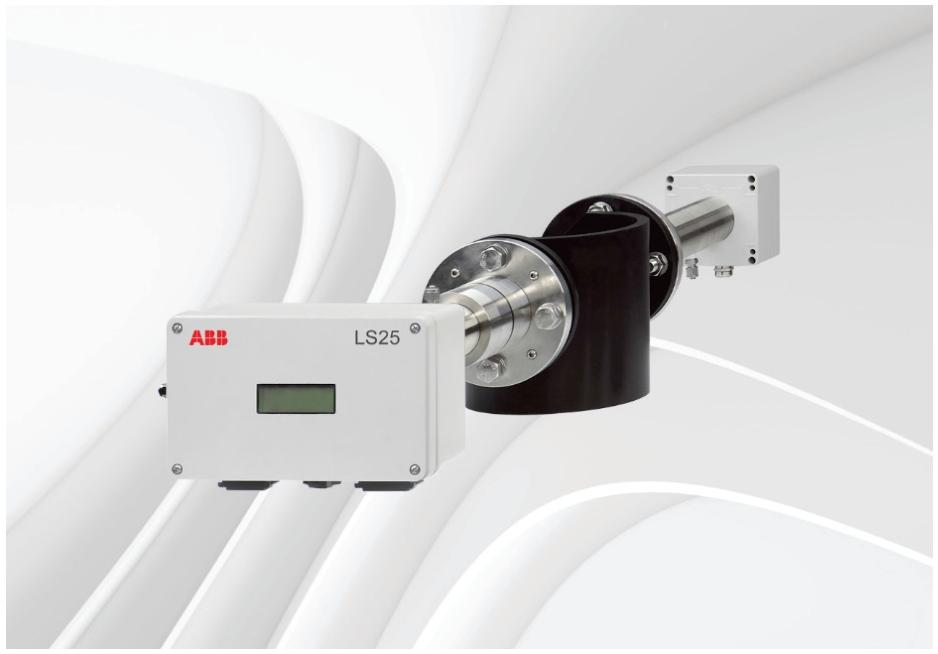
AO2000-LS25 is a laser analyzer launched by ABB, available in both universal and explosion-proof versions, designed to make measurement simple. It is based on the principle of Tunable Diode Laser Absorption Spectroscopy (TDLAS) and consists of three independent units: transmitter unit, receiver unit, and power supply unit. It can be used for continuous in-situ gas monitoring in chimneys, pipelines, process rooms, and other places.
Measurement principle
Using infrared single line absorption spectroscopy, each gas has a unique absorption line at a specific wavelength. By scanning the absorption line of the target gas and using wavelength modulation technology, the gas concentration is measured using second harmonic signals, and the measurement is only for free molecules of specific gases, without being affected by molecules that bind to other molecules or adhere to particles.
Instrument Description
Transmitter unit: including laser module, collimating optical components, and main electronic equipment, placed in a coated aluminum box.
Receiver unit: equipped with a focusing lens, photodetector, and receiving electronic device, also inside a coated aluminum box.
Power supply unit: converts 100-240V AC to 24V DC, which can directly supply power to the transmitter unit and connect 4-20mA input signals from external temperature/pressure sensors.
Protection and Performance: The protection level of the transmitter and receiver units is IP66, and the standard optical window can withstand an absolute pressure of up to 5 bar. The optical alignment is simple and reliable, and the blowing function can prevent dust and other pollutants from contaminating the optical window.
Software
User invisible programs integrated into CPU electronic devices, used to perform all necessary calculations and self-monitoring tasks.
A Windows based program that communicates with the instrument through an RS-232 connection for installation, service, and calibration, and does not require use during normal operation.
Laser classification and warning
When measuring oxygen, the laser is classified as Class 1M, and other sample components are classified as Class 1, in accordance with IEC 60825-1 standard. The laser emits invisible light.
Warning: 1M class laser products cannot be opened when powered on and cannot be viewed directly with optical instruments; Class 1 laser products cannot be opened when powered on.
Installation preparation
(1) Tools and other equipment
Two M16 bolt open-end wrenches, one 5mm hex wrench, one 2.5mm flathead screwdriver, and one 386 or higher configuration PC are required.
(2) Measurement point flow conditions
It is recommended to have at least 5 straight pipe sections with chimney diameters before the measurement point, and 2 straight pipe sections with chimney diameters after it.
(3) Monitor placement
The transmitter and receiver units should be easily accessible, and the receiver unit should have at least 1 meter of free space outward from the flange fixed on the chimney.
(4) Requirements for flanges and chimney holes
Two holes with a diameter of at least 50mm and diametrically opposite are required. The standard flange is DN50/PN10. The initial angle and alignment of the flange after welding must meet certain tolerance requirements. After adjustment, the maximum allowable angle drift between the laser beam and the central axis of the receiver unit caused by temperature or vibration is ± 0.3 °.
(5) Cable and electrical connections
The transmitter and receiver units are connected using the accompanying receiver cable, with a modified cable length not exceeding 20 meters.
The service PC cable is 3 meters long and can be extended to about 10 meters.
The maximum length of the power cable is 100 meters, the maximum length of the receiver cable is 150 meters, and the maximum length of the Ethernet cable is 100 meters or longer (depending on the local network configuration).
Installation
(1) Installation and adjustment
Install the alignment and blowing unit of the transmitter and receiver onto the flange according to the steps, perform blowing gas installation, window adapter ring installation, equipment body installation, cable connection and other operations.
Air blowing is used to keep the instrument window clean. The blowing gas should be dry and clean. It is recommended to use instrument air with a flow rate of about 20-50 liters/minute. Some applications require nitrogen blowing. The blowing flow rate of the transmitter and receiver units should be less than 0.5 liters/minute.
For applications involving toxic and highly corrosive gases, isolation flanges should be used, and process safety or thorough purging should be ensured before installation.
(2) Start up
When the electronic device is started, the LCD will display the startup mode information. The laser will only be turned on after the laser temperature stabilizes during the startup process, and the startup usually lasts less than 3 minutes.
After startup, it may display “laser alignment error” and “low transmission”, which are normal phenomena indicating that the transmitter and receiver units are not aligned.
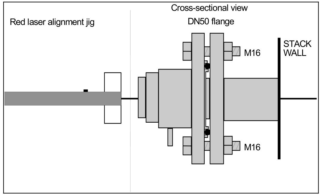
(3) Use a red laser to align the fixture with the transmitter/receiver
Alignment of transmitter unit: Remove the adapter ring, install the red laser alignment fixture, adjust to find the laser beam and move it to the center of the hole, and lock the alignment.
Receiver unit alignment: Similar to the transmitter unit alignment steps, reinstall the transmitter and receiver after completion, and check the transmission readings.
(4) Tune to achieve maximum transmission
Measure the alignment voltage with a voltmeter, adjust the adjustment screws on the transmitter and receiver sides to maximize the voltage reading, repeat until there is no further improvement, and tighten the locking screws.
(5) Connect PC
Copy the service software to the PC, connect the instrument via RS-232 or network, and set parameters such as process gas pressure, temperature, and concentration units.
Service Program
(1) Software startup
Select the connection method (serial port, modem, LAN, or demo mode), enter the IP address and port number, and start in user mode or advanced mode. The user mode interface is simplified, and the advanced mode requires a password.
(2) Measurement menu
Display parameters such as status, serial number, mode, concentration, line width, and transmission, which can be accessed through buttons to access different menus. The screen update cycle defaults to 5 seconds.
(3) Program menu
Draw Readings: Draw the measured average and instantaneous gas concentration, transmission, and spectral temperature (if applicable).
Second harmonic signal: displays the signal used to calculate gas concentration, which can be saved to a file for later analysis.
Record Reading: Record measurement data to an ASCII file with customizable sampling period, file name, and recording parameters.
View error logs: Download instrument error and warning logs, save or clear logs.
Measurement configuration: Set pressure and temperature input methods, optical path parameters, concentration averaging, instrument time, etc.
Gas specific parameters: select the measured gas, unit, output format, alarm level, etc.
Calibration instrument: There are two modes: proportional calibration and global calibration. Proportional calibration adjusts proportionally based on measurement and provided concentration, while global calibration also adjusts line width parameters, requiring stable reference gas conditions.
TCP/IP and modem configuration: Set IP address, subnet mask, port number, and gateway.
File download/upload: Download instrument readings and settings to PC, or upload settings from PC to instrument.
Manual instrument control: Force the instrument into sleep mode, reset the microcontroller, test the current circuit and digital I/O, etc.
(4) Configure through AO2000 central unit
The parameters of the laser analyzer can be configured through the AO2000 display and control unit, which has the same effect as using service software, including setting gas concentration units, temperature and pressure input methods and values, optical path parameters, etc.
Operation, maintenance, and calibration
(1) Operation mode
Startup mode: After booting up, perform initialization, self-test, and startup until the laser temperature stabilizes within an acceptable range.
Measurement modes: including normal, zero and span modes. Normal mode outputs measurement data periodically, while zero and span mode is used to verify instrument performance.
Fault mode: When the instrument detects a serious fault, it enters, stops measuring, and automatically attempts to restart after one hour.
(2) Maintenance
Daily maintenance: Regularly inspect optical transmission, clean windows and adjust alignment if necessary. For zero gas applications, test instrument response at least once every three months and check calibration every 3-12 months.
Clean the optical window: When the transmission drops below the reliable measurement level, clean it with non abrasive detergent or solvent. If there are cracks or damage, replace it.
Instrument alignment: When the alignment changes due to external stress, re align according to the installation procedure.
(3) Optimize flange blowing flow rate
There are two methods to determine the required purge flow rate: one is to turn off and turn on the purge flow, and analyze and measure concentration changes; Another approach is to adjust the measurement length and compare the concentration, and adjust the purge flow rate based on the results.
(4) Instrument calibration
The instrument has been calibrated with a certified gas mixture before leaving the factory, and does not require calibration after receiving it. After a period of use, it may need to be recalibrated due to laser aging. It is recommended to verify calibration annually with certified test gas and the provided gas pool.
Calibration requires the instrument to run for at least 1 hour, connect to the test cell, set the correct measurement configuration parameters, introduce calibration gas, stabilize, calibrate, and save the settings.
For reactive and “viscous” gases, stainless steel or PTFE tanks, shortest connecting pipes, and high flow blowouts should be used to ensure stable concentration.
(5) Troubleshooting
The LCD displays various fault messages, such as “low transmission”, “laser alignment error”, “PLC reading error”, etc. Based on the message explanation, corresponding measures are taken, such as cleaning the window, checking the connection, adjusting the alignment, etc. If the problem cannot be solved, download the error log and system log and contact the service personnel.
Electrical connection
(1) Transmitter unit interface
There are receiver connectors, main power connectors, service connectors, and network connectors, which are used to connect receiver cables, power and sensor inputs, service PCs, and Ethernet, respectively.
(2) Receiver cable connection
Detailed wiring of the receiver cable at both ends, including power supply, signal, temperature sensor, etc.
(3) Power cable connection
The wiring at both ends of the power cable includes temperature, pressure, flow probe input, and power input.
(4) RS-232 and Ethernet connectors
The functions of each terminal of the RS-232 connector and the wiring of the Ethernet RJ-45 connector.
(5) Ethernet connection to AO2000
According to the AO2000 software version, the method of connecting one or more laser analyzers is introduced, including IP address setting and network topology structure.
(6) Current circuit (4-20mA) input connection
The connection method of active and passive 4-20mA current loop input probes was demonstrated, and multiple instruments can be connected in series to the same probe.
(7) Power cable connection
The power cable is connected to the power supply unit, and the cable diameter should be within the range of 5-10mm. The power terminal can accommodate conductors with an area of less than 2.5mm ².
(8) Transmitter board – fuse and LED
The transmitter board has a main fuse and some LEDs to indicate the status of different power supply voltages. If the LEDs are abnormal, the fuse and power supply need to be checked.
Leave a comment
Your email address will not be published. Required fields are marked *