The ABB AX400 series conductivity analyzer is an industrial grade monitoring device that supports single/dual sensor inputs. It has three installation methods: wall mounted, pipeline mounted, and panel mounted. Its core function is to continuously monitor conductivity and support temperature automatic compensation (compatible with Pt100/Pt1000 sensors). The measurement range is 0~10000 µ S/cm, and the accuracy is better than ± 1% reading; The device is equipped with dual 5-digit LCD backlit display screens and a 5-key operation panel, supporting 4 analog output ranges (0-10mA/0-20mA/4-20mA, etc.), 3-5 relay outputs, and can be configured with 5-digit safety codes to protect parameters. It also provides functions such as sensor calibration, alarm settings, and fault diagnosis, and is widely used in industrial scenarios such as chemical, pharmaceutical, and water treatment.
Product Overview
Basic positioning
The ABB AX400 series is an industrial grade conductivity analyzer designed for continuous monitoring and control of fluid conductivity in industrial processes, supporting single or dual sensor inputs.
The equipment has automatic temperature compensation function, which can correct the measured value to the standard reference temperature of 25 ℃, ensuring data accuracy and suitable for complex industrial environments.
Core strengths
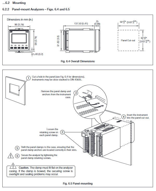
Multiple installation methods are compatible: wall mounted, pipeline mounted, and panel mounted to meet different site layout requirements.
High protection and stability: protection level IP66/NEMA4X, working temperature -20~65 ℃, storage temperature -25~75 ℃, humidity ≤ 95% RH (no condensation).
Flexible output and alarm: supports analog signal retransmission, relay alarm, and can adapt to various industrial control systems.
Safe and convenient operation: Parameters are protected from accidental changes through a 5-digit security code, and the backlit display screen supports multilingual switching.
Core technical parameters
Category key parameter details
Conductivity measurement range: 0~0.5~10000 µ S/cm (supports multiple electrode constants)
Units µ S/cm, µ S/m, mS/cm, mS/m, M Ω· cm, TDS
Accuracy better than ± 1% reading
Temperature related compensation range -10~150 ℃ (14~302 ° F)
Programmable temperature coefficient of 0-5%/℃, supporting fixed curves such as HCl/NaCl/NH3
Sensor type Pt100/Pt1000 (programmable selection)
Output configuration analog output 2-channel standard (4-channel optional), isolated, supports 0-10mA/0-20mA/4-20mA
Relay output with 3 standard channels (5 optional), single pole double throw, contact capacity 5A/115/230V AC
Power supply and power consumption power input 85-265V AC 50/60Hz; Optional 12-30V DC/24V AC
Power consumption<10VA
Operation and Function Configuration
(1) Operation interface and buttons
Display screen: Dual 5-digit 7-segment LCD (displaying measured values such as conductivity and temperature)+16 character dot matrix screen (displaying units and menu information), supporting backlight on/automatic mode.
Button function: 5 thin film buttons, which respectively realize menu switching, page scrolling, parameter adjustment, confirmation and saving operations.
(2) Core functional modules
sensor configuration
Supports single/dual sensors (Sensor A/B), with the ability to set conductivity units, electrode constants (0.01~10 cm ⁻¹), temperature compensation types, TDS coefficients (0.4~0.8), and units (ppm/mg/l/mg/kg).
In dual sensor mode, data calculation methods can be selected: difference (A-B), ratio (A/B),% pass rate (B/A × 100),% retention rate ((1-B/A) × 100), and derived pH (requiring NH3/NaOH temperature compensation).
Calibration function
You need to enable the ‘Enable Cal.’ permission and enter a 5-digit calibration code to perform calibration.
Calibration parameters: sensor slope (0.2000~5.000), sensor offset, temperature slope (0.2000~1.500), temperature offset (-40.0~40.0 ℃), support resetting to default values.
alarm configuration
Supports 3-5 alarm channels, with adjustable alarm types (off/alarm/status), associated parameters (conductivity/temperature or calculated values of sensors A/B), safe mode (Yes/No), action type (high/low), set value, hysteresis (0-5%), and delay time (0-60s).
Output configuration
Analog output can be assigned to measurement parameters or temperature, supporting linear/bilinear/2 decade logarithmic/3 decade logarithmic curves.
Fault default output: can be set to turn off/hold/drive to default value (0~22mA).
(3) Security protection
Parameter protection: Modifying the configuration requires entering a 5-digit security code (00000~19999) to prevent unauthorized operations.
Calibration protection: Calibration operation requires inputting a 5-digit calibration code to avoid incorrect calibration affecting accuracy.
Installation and maintenance
(1) Installation requirements
Installation environment: Keep away from excessive vibration, harmful vapors, and dripping liquids. It is recommended to install at a visual height for easy operation and observation.
Distance between electrode and analyzer: maximum 50m for electrode constant<0.1, maximum 100m for electrode constant ≥ 0.1.
Wiring specifications: The power supply must be grounded, and signal cables and power cables should be wired separately. It is recommended to use shielded twisted pair cables, with the shielding layer connected to the grounding column of the shell.
(2) Calibration and maintenance
Calibration preparation: A standard resistance box (0~10k Ω, accuracy ± 0.1%) and a digital milliampere meter (0~20mA) are required.
Calibration process: Disconnect the sensor → Connect the calibration device → Enter the calibration menu → Adjust slope/offset → Save parameters.
Daily maintenance: Regularly clean electrodes, check cable connections, and recalibrate if measurement deviations occur.
(3) Fault diagnosis
Possible causes and troubleshooting measures for fault phenomena
Display error code “FAULT TYPE 0001” sensor connection loose/electrode damaged. Check the sensor wiring and replace the electrode
Conductivity unresponsive, electrode contamination/incorrect parameter settings. Clean the electrode and verify the electrode constant and temperature compensation settings
Abnormal temperature reading. Temperature sensor malfunction/wiring error. Check Pt100/Pt1000 wiring and replace the sensor
Alarm does not trigger alarm setting value error/excessive hysteresis. Reset alarm parameters to reduce hysteresis
Applicable scenarios
Chemical industry: Monitor electrolyte solution concentration and changes in conductivity during reaction processes.
Pharmaceutical industry: Quality monitoring of purified water and water for injection (WFI).
Water treatment industry: reverse osmosis system, ion exchanger effluent monitoring.
Food and beverage industry: Control of solution concentration during production processes (such as saltwater and syrup).

Leave a comment
Your email address will not be published. Required fields are marked *