Basic Information
Core product portfolio
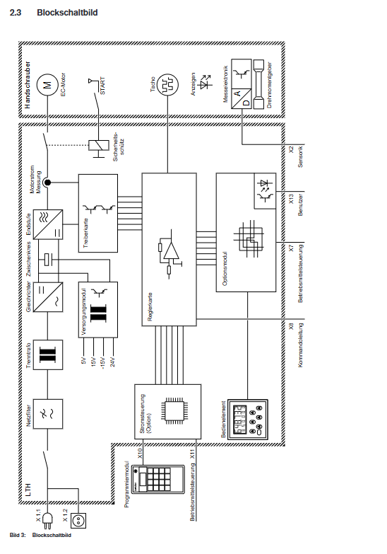
SE 200 Controller: The core control unit of the electric tool system, responsible for program selection, job control, and status feedback.
LTH power unit: a frequency converter that provides a variable power/frequency rotating magnetic field for EC motors, available in two specifications: 230V (order number 0 608 750 056) and 110V (order number 0 608 750 064).
Document type and purpose: Official technical manual, covering safe operation, installation and wiring, functional settings, fault handling, etc., suitable for electric tightening/loosening operation systems in industrial assembly scenarios.
Adapt devices and accessories
Suitable motors: EC 37, EC 48 type EC motors (such as ECH12-MG, ECH37-MG, etc., please refer to the appendix for order numbers).
Core accessories: current control board ST1, programming module PM-1, dedicated connection cable (straight 1.6-10m/spiral 6.3-10m).
Core Technical Parameters
Parameter Category Specific Parameters LTH 230V LTH 110V Remarks
Power supply parameters rated voltage 220-240V AC 100-110V AC 50/60Hz ± 10%
Maximum input current 10A 20A-
Power consumption 400VA 400VA-
Output parameters Output voltage range 0-230V 0-230V-
Rated output current 2A 2A-
Maximum output current 12A 12A-
Output frequency range 0-500Hz 0-500Hz, suitable for motor speed regulation
Physical dimensions (length x width x height) 310 × 160 × 310mm 310 × 160 × 310mm-
Weight 13.4kg 13.4kg including installation accessories
Environmental parameters Operating temperature 0-50 ℃ 0-50 ℃-
Storage temperature -20-70 ℃ -20-70 ℃-
Relative humidity 20-90% (no condensation) 20-90% (no condensation)-
Protection and Electromagnetic Compatibility Protection Level IP 42 IP 42 Solid Foreign Object Protection+Splash Protection
EMC level IEC 801 level 4 IEC 801 level 4 Anti electromagnetic interference
Data storage battery specifications: 2 1/2 AA 3.6V lithium batteries, 2 1/2 AA 3.6V lithium batteries, data storage for 8 years
Key points of safety regulations
Electrical safety
After power failure, it is necessary to confirm that there is no voltage before operation to avoid the risk of high voltage electric shock.
It is strictly prohibited to connect the motor to the PE line. Electrical isolation should be achieved by relying on the isolation transformer of the LTH power unit (in accordance with VDE 0551 standard).
The fuse (6.3A slow melting type) is only allowed to be replaced by professionals and unauthorized modification of the circuit is prohibited.
Operational Security
Only trained and qualified personnel are allowed to operate, and they must be familiar with safety regulations and equipment functions.
In environments with severe dust or high humidity, the LTH unit needs to be installed in a control cabinet with an IP 54 protection level.
It is prohibited to connect non specialized equipment (such as coffee makers, toasters, etc.) to IEC sockets.
Equipment Protection
During installation, a ventilation gap of ≥ 40mm should be reserved to avoid overheating caused by poor heat dissipation.
Transportation and storage should avoid severe vibration, condensation, and dust pollution.
Installation and wiring specifications
(1) Installation requirements
Installation method: Hanging installation is carried out through the back hanging ears, without the need to be in close proximity to power tools.
Cable limitation: The maximum length of the cable between the LTH power unit and the motor should not exceed 50m, and original factory specific cables must be used.
Environmental adaptation: Install directly in regular environments, but in harsh environments, an IP 54 control cabinet is required.
(2) Core Interface Definition (Summary of Key Interfaces)
Interface Identification Type Pin Count Core Function Key Pin Description
X1 (Netz) IEC socket 3 (L/N/PE) power input L=phase wire, N=neutral wire, PE=ground wire
X3 (Handschauber) circular plug 19+PE motor connection U/V/W=motor phase line, TMA=motor temperature sensor
X2 (Sensorik SE200) SUB-D socket 15 sensor signal CLK/DATA=RS422 serial signal, 24VSE=control power supply
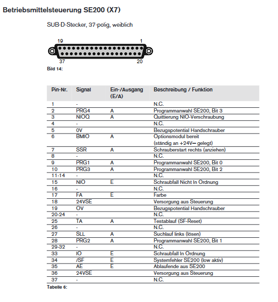
X7 (Betriebsmittelsteuerung) SUB-D socket 37 material control SSR=tighten start, SLL=loosen start, IO/NIO=job success/failure signal
X8 (Kommandoleitung) SUB-D plug 25 command line ST1-ST3=speed gear, FG=release signal, IM1/IM2=torque measurement
X13 (Benutzerschnittstelle) SUB-D plug 15 user interface SIO=IO count output, SF=system fault, TA=test reset
(3) Wiring process
Connect the interface cable and secure it with screws to ensure reliable contact.
Insert the Amphenol plug into the motor and tighten the locking ring.
Connect the power cable (IEC plug) and secure it with a wire clamp.
By turning on the bottom power switch, the device automatically performs hardware self-test.
Operation and Function Description
(1) Core components of panel operation
Motor selection switch: Switch the EC 37/EC 48 motor type, and the corresponding LED indicator light will light up to confirm.
Program selection mode:
Internal mode: Select the 0-15 program through the panel buttons (even=tighten P0, odd=tighten P1, 15=loosen SLL).
External mode: Select the program using hexadecimal code through the X13 interface, and the “ExternalN” LED will light up.
IO Count Statistician:
Function: Record the number of qualified assignments (0-999999), supporting cumulative/decreasing modes.
Operation: Reset with the red SET button, set preset values with 6 buttons, and display “Lo bat” for low battery.
Fault handling: Reset the fault by pressing the “RESET” button. If the power module fails, the device needs to be restarted.
(2) Core functional parameters
Parameter Name Optional Setting Default Value Function Description
Count mode: Add/SubAdd: Count from 0 to the preset value; Decrease: Count from preset value to 0
Loop mode: On/Off Off On=Delay reset loop after reaching the preset value; Off=continuous counting without looping
Relay output type when NO (normally open)/NC (normally closed) NO count meets the standard
Delay 100/200/300/400/500ms – SIO signal duration when Loop=On
DP (decimal point) with no/1/2 decimal places and no count display
(3) Homework process
Select motor type (EC 37/EC 48) and program mode (internal/external).
Set the preset value and working parameters of the IO counter (accumulate/decrease, loop, etc.).
Trigger the operation (tightening/loosening) through the X7 interface or motor start button.
After the homework is completed, the IO/NIO signal feedback indicates success or failure, and the counter is automatically updated.
When there is a malfunction, the corresponding LED lights up, and after resetting, the operation can be restarted.
Fault diagnosis
(1) Common faults and LED indications
LED identification color fault type handling method
USP red middle circuit overvoltage check power supply voltage, reset device
If the NTF red power module fails, restart the device. If it is ineffective, return it to the factory for repair
TF/TFVM red temperature fault (unit/motor), restart after cooling, check heat dissipation and temperature sensor
FI red current fault (short circuit): Check the motor cable and eliminate the short circuit point
BL red motor stalling check load, eliminate mechanical jamming
Accessory ordering information (core accessories)
Accessory category Product name Order number Remarks
Power Unit LTH 230V 0 608 750 056-
LTH 110V 0 608 750 064 –
Controller SE 200 Electric Tool Control 0 608 830 123-
Motor ECH37-MG 0 608 841 009 EC 37 type
ECH48-MG 0 608 841 010 EC 48 type
Cable straight cable (4.0m) 0 608 750 067 motor connection
Spiral cable (6.3m) 0 608 750 070 motor connection
Control module current control board ST1 0 608 750 054 optional accessories
Programming module PM-1 0 608 750 055 optional accessories
Leave a comment
Your email address will not be published. Required fields are marked *