1、 The official operation guide for Bosch Rexroth EcoDrive 03 series drive controller (model DKC.3-040/-100/-200) specifies that the document is intended for professionally trained electrical installation personnel. The core content includes safety precautions, product identification rules, rated parameters and dimensions, wiring and installation specifications, reference documents, and appendix instructions. It emphasizes the need to strictly comply with electrical safety and equipment protection requirements during operation. At the same time, it standardizes the installation, use, and maintenance points of key components such as control voltage connection, motor wiring, temperature monitoring, and braking system of the drive.
2、 Safety precautions
Electrical contact safety
There is a high voltage risk in the driver. After power failure, it is necessary to wait for 30 minutes for the capacitor to discharge, and the measured capacitor voltage must be below 50V before operation.
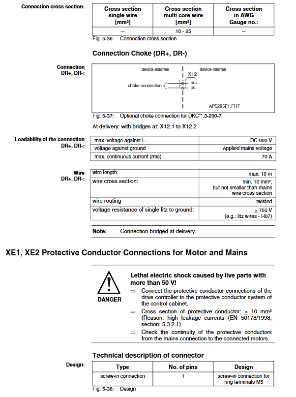
The grounding conductor must use copper wire with a cross-sectional area of ≥ 10mm ² and must be permanently and reliably connected.
Do not touch electrical connection points while powered on. Install a protective cover before turning on the device.
Handling and assembly
Suitable tools and lifting equipment should be used to avoid squeezing and shearing injuries.
Wear protective equipment such as goggles, safety shoes, and gloves when necessary.
Prevention of dangerous sports
Motor wiring errors, improper parameter settings, sensor failures, etc. can all cause dangerous movements.
Safety fences, light curtains and other protective devices need to be installed. The emergency stop switch should be installed within the reach of the operator, and the effectiveness of the emergency stop function should be verified before starting.
The vertical axis requires additional mechanical locking or external braking devices, and the standard motor brake does not meet personnel safety protection requirements.
Electromagnetic and High Temperature Protection
Pacemakers and metal implant wearers are prohibited from entering the equipment operation or installation area. If they need to enter, they must consult a doctor.
The temperature of the motor and driver casing during operation may exceed 60 ℃, and the cooling time can reach up to 140 minutes. Avoid touching high-temperature components.
3、 Product Identification and Supply Scope
Model code rules
Model example: DKC03.3-040-7-FW, where 040 represents the rated current of 40A and FW represents the firmware module that needs to be ordered separately.
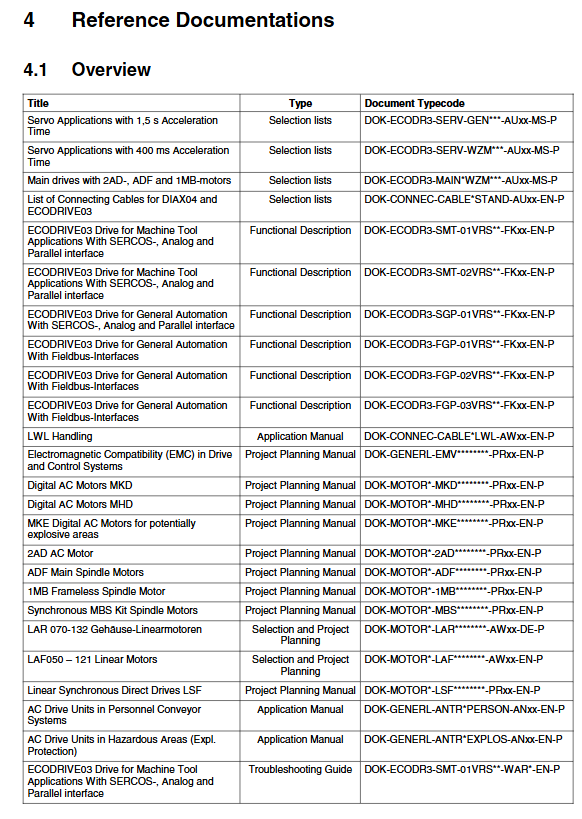
Scope of supply
Including firmware modules, contact protection devices, and corresponding connector models, there are differences in connector configurations for different types of drivers.
4、 Rated parameters and dimensions
Core Rated Parameters (Table)
|Parameter | Unit | DKC03.3-040 | DKC03.3-100 | DKC03.3-200|
|Rated control voltage | V | 24 DC | 24 DC | 24 DC|
|Rated input voltage | V | 200-480 AC | 200-480 AC | 200-480 AC|
|Maximum output current | A | 40 | 100 | 200|
|Maximum output frequency | Hz | 1000 | 1000 | 1000|
|Equipment weight | kg | 5.7 | 9.7 | 19.5|
|Maximum ambient temperature (rated data) | ℃ | 45 | 45 | 45|
Installation spacing requirements
The minimum distance between the top of the equipment is 150mm, and the minimum distance between the bottom is 80mm. It is necessary to ensure that the heat dissipation air duct is unobstructed.
5、 Usage and installation specifications
Wiring specifications
Control voltage connection (X1): using 2 × 4 spring contact connectors, with a single core wire cross-sectional area of 0.2-2.5mm ², supporting parallel power supply for multiple drivers, and a maximum loop current of 10A.
DC bus/motor/power connection (X5): M5 screw terminal block is used, with a tightening torque of 2.5-3.0Nm. The maximum length of the motor cable is 75m (at 4kHz switching frequency), and the original cable from Lishle must be used, otherwise the warranty will be lost.
Temperature monitoring and brake connection (X6): responsible for motor temperature monitoring (PTC/NTC resistance) and brake control. The maximum switching voltage of the brake is 40V DC, and the maximum switching current of the DKC * *. 3-200-7 model is 4A.
Programming module connection (X7): includes parameter module and firmware module, set driver address (1-99) through S2/S3 dip switch.
Installation requirements
Proper electrostatic protection is required, and operators and tools must be grounded to avoid electrostatic damage to electronic components.
Signal lines and power lines need to be wired separately, and shielded wires are required for analog signals.
The control cabinet needs to have a reasonable layout of cooling units to avoid condensation water droplets falling onto electronic components.
Leave a comment
Your email address will not be published. Required fields are marked *