The ABB S500 series distributed automation I/O hardware technical manual focuses on the remote I/O module system of the PROFIBUS-DP protocol, covering three core hardware types: bus module, expansion module, and expansion box. It specifies the model parameters, installation specifications, wiring methods, parameter configuration, and fault diagnosis of each module, supports a maximum transmission rate of 12 Mbit/s, adapts to storage environments of -25 ℃~+75 ℃ and working environments of 0 ℃~+55 ℃, and sets the station address (1-125) through DIP switches to flexibly combine digital/analog input and output functions, providing a stable and reliable hardware solution for industrial automation distributed control.
Core strengths
Modular design: Supports flexible combination of bus modules, expansion modules, and expansion boxes to adapt to different I/O requirements.
High compatibility: Complies with EN 50170 standard, supports transmission rates of 1.5-12 Mbit/s, and is compatible with various industrial scenarios.
Comprehensive protection and diagnosis: equipped with reverse polarity protection, short circuit protection, real-time feedback status of LED indicator lights, and support for uploading diagnostic data.
Hardware classification and core parameters
(1) Bus module
Model Transfer Rate I/O Configuration Core Features
DX 501-DP 1.5 Mbit/s 8DI+8DO basic bus module, supporting the expansion of 7 modules
DX 502-DP 12 Mbit/s 8DI+8DO high-speed model, suitable for large data transmission scenarios
(2) Expansion module
Type, Model, Core Configuration, Key Parameters
Digital I/O DX 511 8DI+8DO input delay 0.1~32ms, output single channel 0.5A
Digital input DI 511 16DI input current 5mA/channel, supports 2-wire proximity switch
Digital output DO 511 16DO module total current 8A, switching frequency ≤ 100Hz (resistive load)
Analog I/O AX 511 4AI+4AO resolution 11-12 bits, input range ± 10V/± 20mA/4-20mA
Analog input AI 511 4AI sampling time ≤ 2ms/channel, measurement error ≤ ± 0.4% FS
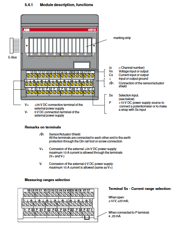
Simulate input AI 512 8AI with the same parameters as AI 511, doubling the number of channels
(3) Expansion box
Key characteristics of model configuration
AX 501 3AI+1AO 8-bit resolution, conversion time 1.64ms
DI 501 4DI 2-wire connection, typical input delay of 3ms
DO 501 8DO single channel 0.1A, supports Interfast board connection
Installation and wiring specifications
(1) Installation requirements
Fixed method: Supports DIN rail (35 × 7.5/15mm) or screw fixation, with a grounding resistance of ≤ 0.5 Ω.
Installation spacing: When installed horizontally, the distance between the cable tray and the module should be ≥ 20mm, and mechanical limits should be added for vertical installation.
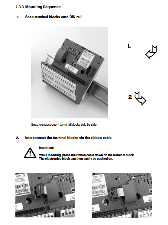
Installation sequence: First fix the terminal block → interconnect with flat cable → insert electronic module → wire.
(2) Wiring parameters
Terminal type, wire diameter range (solid), wire diameter range (multi strand), stripping length, tightening torque
Screw terminal 0.2~4mm ² 0.22~2.5mm ² 7.5mm 0.4~0.6Nm
Spring terminal 0.12~2.5mm ² 0.12~2.5mm ² 6mm-
(3) Power Supply and Protection
Power requirements: Rated 24V DC, allowable range 19.2-30V DC, ripple ≤ 5%, with reverse polarity diode protection.
Fuse configuration: The terminal module is equipped with 8A fast melting fuses (5 × 20mm) for overload/short circuit protection.
Environmental protection: working temperature range of 0~+55 ℃, storage temperature range of -25~+75 ℃, protection level of IP20.
Configuration and Diagnosis
(1) Address and parameter configuration
Station address: Set through DIP switch, range 1-125, only read when powered on.
System configuration: Supports up to 7 expansion modules and 1 expansion box, with a maximum input/output data size of 128 bytes each.
Software configuration: Corresponding GSD files are required (DX 501-DP corresponds to ABB_9521. GSD, DX 502-DP corresponds to ABB_9520. GSD).
(2) LED indicator diagnosis
LED name status meaning
Pw (power supply) is on, and the system power supply is normal
BY (Busy) Flash expansion module quantity exceeds limit or data capacity exceeds limit
OF (output fault) lights up. Output short circuit, overload, or loss of load power supply
Err (incorrect) flashing system configuration error or module failure
(3) Fault handling
Common faults: PROFIBUS communication timeout, parameter configuration mismatch, output short circuit, power loss.
Diagnostic data: The module will send a 19 byte diagnostic message to the DP master station, including fault type, channel information, etc.
Recovery method: After troubleshooting, power off and restart, or reset the configuration through the main station software.
Key Limitations and Precautions
Module quantity limit: Each bus module can connect up to 7 expansion modules to avoid exceeding the E-Bus capacity.
Cable requirements: PROFIBUS cables must comply with the EN 50170 standard, with a characteristic impedance of 135~165 Ω and a wire diameter of ≥ 0.64mm.
Signal isolation: There is no channel isolation between modules, and analog signals require shielded cables with single point grounding on the shielding layer.
Leave a comment
Your email address will not be published. Required fields are marked *