The SIMO-MM3 function block (FB621) in the Siemens DRVPCS7 software library is used to integrate the third-generation MICROMASTER frequency converter into the SIMATIC PCS 7 process control system. It supports PROFIBUS DP communication and has three operation modes: manual/automatic/local, standardized processing of set values/process values, fault alarm and diagnosis, maintenance management, etc. Visual operation and monitoring can be achieved through a panel (Faceplate). It is compatible with controllers such as S7-400 and needs to be installed and used with the Drive ES PCS7 plugin. It is suitable for frequency converter integration control scenarios in industrial automation.
Basic Information and Installation
1. Applicable scenarios and core specifications
Specific project content
Compatible with third-generation MICROMASTER frequency converter (requires PROFIBUS DP module CB15/CB155)
The control system requires SIMATIC PCS 7 V8.2 and above, supporting controllers such as S7-400
Communication specification PROFIBUS DP, process data: send/receive 6 characters each (4 characters parameters+2 characters process data)
Function block core information name: SIMO-MM3, number FB621, programming language SCL, instance DB working memory 686 bytes
2. Installation process
Software installation: Insert the Drive ES PCS7 CD, run Setup. exe, and the components will be automatically installed to STEP 7 (s7libs directory) and WinCC directory.
Project configuration: Create a project in SIMATIC Manager, insert it into the PC station and configure it. When compiling the OS, check “Generate module drivers” to generate module drivers.
Panel installation: Copy user objects from the template file (@ template_SRVPCS7. pdl) to the process screen, and associate process labels through dynamic guidance.
Core functions and operating modes
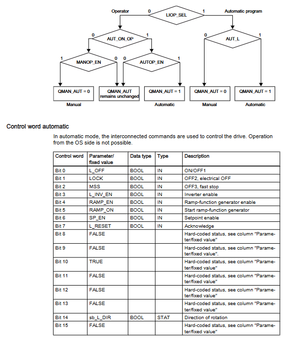
1. Detailed explanation of operating modes
Mode type control source key characteristics switching conditions
Automatic mode (control room) Automatic program (CFC/SFC) The control word is set by the program and supports external setting values (SP.ET) LIOP_SEL=1, AUTOP_EN=TRUE
Manual mode (control room) operator panel (OS) control words are operated by the panel and only support positive set values LIOP-SEL=0, MANOP-EN=TRUE
The local mode driver does not have control permissions in the local operation control room, and supports control word tracking (TRACK_CW) with REMOTE=0. Driver parameter configuration is required (P51/P52/P53=9)
2. Core Function Description
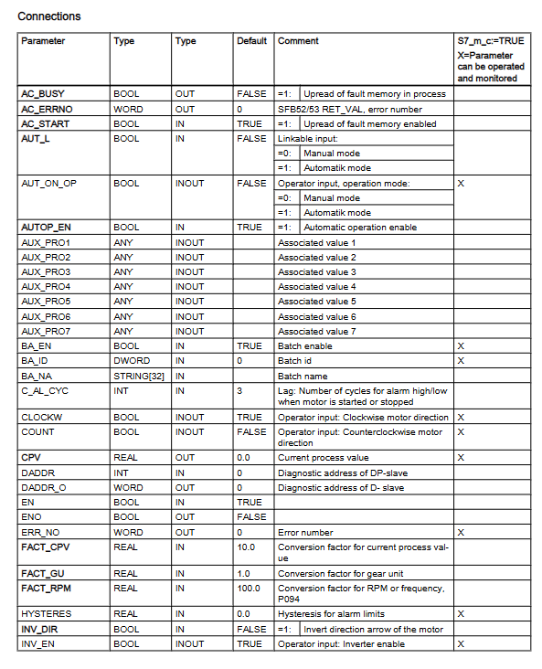
Standardization of set values/process values:
Standardization factor calculation: Basic factor=16384/ACT_SPM; When equipped with a gearbox=16384/(FACT_SPM × FACT_CU)
Process Value Conversion: Current Process Value (CPV)=Actual Value/FACT_CPV (default 10)
Fault diagnosis function:
Fault reading: Read the fault memory (P947) of the frequency converter through cyclic communication, with AC-START=1 (communication channel idle) required
Diagnostic signals: support module failure (MODF), rack failure (RACKF), I/O access error (PERAF)
Alarm and message functions:
Message category and triggering conditions:
Fault (F): Parameter assignment error (QPARF), data error (QDAT_SRR)
Fault response (S): Drive failure (QGR_ERR), switch timeout (QTIMEOUT)
Alarm (A): High limit alarm (QALARM-H), low limit alarm (QALARM-L)
Warning (W): Drive Warning (QALARM)
Message blocking: All messages are blocked when MSG_LOCK=TRUE
Maintenance and management functions:
Maintenance cycle settings: MAIN_L (low demand, default 100 days), MAIN_M (medium demand, default 200 days)
Reset operation: Reset maintenance timing through RES-MAIN (panel) or L_RES-MA (program)
Faceplate operation
1. Core control fields of the panel
Core Function Operation Content of Control Fields
Automatic field automatic mode monitoring and configuration mode switching, internal and external setting value selection, STOP operation
Manual field, manual mode control, start stop operation, rotation direction selection (clockwise/counterclockwise)
The message field displays all configuration messages, including message timestamps, categories, and statuses
Fault field driver fault details display fault number, fault text, fault reset
Limit field alarm limit and maintenance configuration setting high/low limit, hysteresis, maintenance reset
Trend field parameter trend display View historical curves of PV/SP/CPV and other parameters
2. Multi language support on the panel
Supports 5 languages including German, English, French, Spanish, and Italian, and can switch languages by modifying fields such as CFC block “Designation” and “Unit” or using the WinCC text library.
Auxiliary functions and compatibility
1. Simulation function
Trigger condition: Set the SIM_SON parameter to TRUE and enable simulation mode (QSIM=TRUE)
Simulation parameters: SIMZSW (status word), SIMPV (process value), SimCPV (current process value)
Function feature: Stop communication with the actual driver during simulation, pause maintenance timing
2. Diagnostic auxiliary block DES-DIAG (FB628)
Core function: Evaluate cyclic events (I/O access errors, rack failures, etc.) and transmit diagnostic information to SIMO-MM3
Call requirement: It needs to be integrated into 7 OBs such as OB32 (Loop Interrupt), OB82 (Diagnostic Interrupt), etc
Key outputs: QMODF (module failure), QRACKF (rack failure), QPERAF (access error)
3. APL library compatibility
Compatible with APL blocks: FB1854 (MotSpdCl, speed control), FB1850 (MotL, linear control)
Connection method: Adapt APL block and SIMO-MM3 input/output structure through conversion block
Operation restriction: SIMO-MM3 needs to be set to automatic mode, and maintenance reset and fault confirmation require calling the corresponding functions through the APL panel
Leave a comment
Your email address will not be published. Required fields are marked *