SINUMERIK 840C is an installation guide for CNC systems equipped with SIMODRIVE 611-D drivers launched by Siemens (September 2001 edition), suitable for machine tool manufacturers. The core content covers system installation prerequisites and visual inspection, universal reset and standard start, PLC installation, MMC area diagnosis, machine data dialog box (MDD), various machine tool data configurations, drive servo start, axis and spindle installation, data backup and other processes. It supports multiple software versions (1. x-6. x), including standard/export versions, emphasizing the importance of safety regulations, electromagnetic compatibility requirements and data backup, while providing practical guidance such as fault diagnosis and parameter configuration.
Core installation and startup process
2.1 Installation prerequisites and visual inspection
Core prerequisites: completion of mechanical and electrical installation, PLC program pre testing, measurement system wiring, compliance of grounding system, and readiness of designated machine tool data
Visual inspection focus:
Module operation: Anti static (prohibit touching printed circuits), only power off to plug and unplug modules
Grounding system: compliant with DIN VDE 0160 standard, star connected to the central grounding point
Cable and shielding: Power cables and control cables are laid separately, and the shielding layer is grounded at both ends
Key components: compliant installation of position encoder, normal operation panel buttons/display
Voltage and Function Test: Automatically perform self check (interrupt controller, memory, CMOS, etc.) after power on, and perform consistency check on the hard drive once a week
2.2 Universal Reset and Standard Startup
Core process (software version 3 and above):
Enter universal reset mode (CSB module startup switch set to 1)
Set time and date, load machine data (configured in MDD)
Memory configuration (DRAM/SRAM allocation, supports flexible settings between 32kB-4920kB)
Exit the universal reset mode (switch set to 0), trigger power on reset
Differences between software version 2 and below: no MDD, direct input of NC/PLC machine data through soft keys, simplified axis/spindle installation process
2.3 PLC Installation and Startup
PLC CPU model: 135 WB2 (with EPROM submodule), 135 WD (no interface PLC)
Start process:
Connect PG 7xx programmer and load STEP5 program
Perform PLC universal reset and clear user memory
Save the program to an MMC hard drive (ANW-PRG file) to avoid data loss
Diagnostic methods: LED displays hardware faults, ISTACK detailed error codes, PLC status monitoring (I/O/flag/timer, etc.)
Detailed explanation of core functional modules
3.1 MMC regional diagnosis
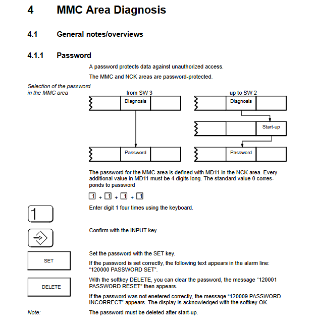
Basic features: password protection (4-digit number, default 1111), multilingual switching (German/English/French, etc.), screen hard copy (TIFF/PCX format)
Core diagnostic function:
NC service: Display service data such as axis/spindle tracking error, actual value/set value, speed set value, etc
Drive service: Monitor MSD (spindle)/FDD (feed axis) status, speed, current, temperature, etc
PC data configuration: Edit CONFIG/FEDCONF files, define language, alarm log format, screen color, etc
Backup function: Backup system/user data through VALITEK tape drive or PC link, supporting software upgrades
3.2 Machine Tool Data Dialogue Box (MDD, Software Version 3 and above)
Core function: Replace traditional list based data input and display machine tool data in actual units
Main modules:
NC configuration: Set the mode group, name, and type (linear/rotational) for channels/axes/spindles
Driver configuration: Select the FDD/MSD module model (such as 6SN112x series), motor type, and activate the module
Machine tool data: including NC/PLC/drive/cycle/IKA data, supporting search, copy, and editing
User display: Customize a list of commonly used machine tool data for easy and quick viewing
3.3 Machine Tool Data Configuration
Key content of data type
NC machine tool data general data (unit, clock), channel data, axis data (resolution, monitoring), spindle data (speed, positioning)
Drive machine tool data FDD (feed axis): motor parameters, speed controller, monitoring limits; MSD (spindle): dual motor support, magnetic flux controller
PLC machine tool data peripheral settings, alarm messages, tool management, computer link configuration
Circular machine tool data measurement/machining of center/channel related parameters of the cycle, supporting repeated calls
3.4 Shaft and spindle installation
Shaft installation:
Resolution setting: Input/position control resolution coordination (e.g. 1 unit MS=2 units position control resolution)
Optimization items: Control direction check, speed setting value matching, servo gain (KV factor), drift compensation
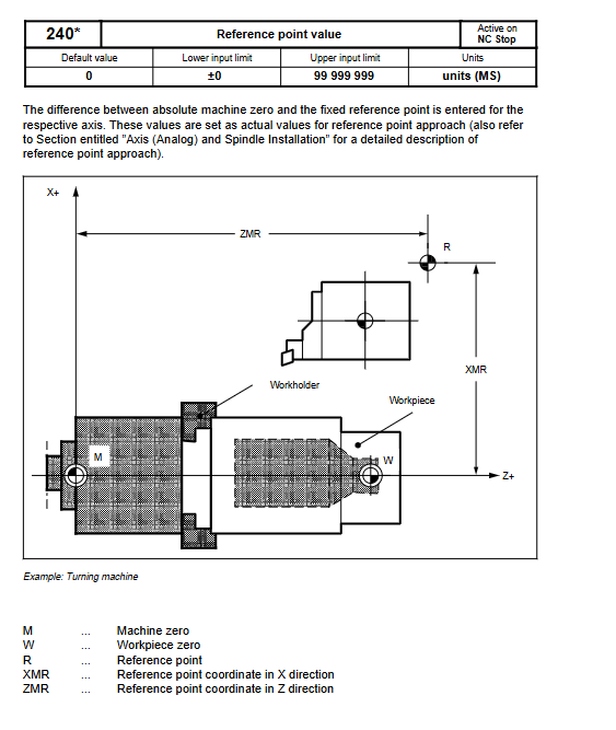
Reference point: Supports automatic direction recognition and program controlled reference point approximation
Spindle installation:
Mode support: open-loop control, oscillation mode, positioning mode (M19 command)
Key parameters: speed limit, gear stage, encoder pulse count (e.g. 1024 pulses per revolution)
3.5 Data Backup and CPU Replacement
Backup methods: tape drive backup (system+user data), PC link backup (software version 6 and above support CD-ROM upgrade)
Backup contents: machine tool data, PLC program, user files, configuration files
CPU replacement process: reload system software after replacement, restore backup data, perform universal reset
Safety and compliance requirements
Security Level Reminder:
DANGER: May cause death/serious injury/significant property damage
Warning: May result in death/serious injury/significant property damage
CAUTION: May cause minor injury or property damage
Electromagnetic Compatibility (EMC): Follow the 6FC 3987-7DB guidelines to avoid external interference affecting the control system
Export compliance: The export version restricts specific functions and requires labeling and software version identification
Fault diagnosis and handling
PLC malfunction: located through LED flashing frequency and USTACK error code, timeout analysis requires disabling buffer access
Drive failure: Monitor DC link status, motor temperature, pulse enable signal, and view detailed data through drive service display
Common issues: Data loss (requiring regular backup), module failure (reconfiguration after replacement), communication errors (checking bus connection)
Leave a comment
Your email address will not be published. Required fields are marked *