Core components of the system
1. On site Control Unit (FCU)
Model Series Type Key Features Adaptation Bus
AFV10 (AFV10S/AFV10D) 19 inch rack mounted (single/dual redundant) supports ESB/ER bus, connecting up to 14 node units ESB bus, ER bus
AFV30 (AFV30S/AFV30D) 19 inch rack mounted (single/dual redundant) supports ESB/optical ESB bus, and EC401/EC402 coupling module ESB bus and optical ESB bus need to be installed
AFV40 (AFV40S/AFV40D) with cabinet (single/double redundancy) standard configuration EC401/EC402, with a maximum of 11 node units ESB bus and optical ESB bus in a single cabinet
2. Node units and relay units
Type, Model, Usage, Core Parameters
ESB bus node units ANB10S/ANB10D single/dual redundant ESB bus connections support all I/O modules, and dual redundancy needs to be installed in pairs
Optical ESB bus node unit ANB11S/ANB11D single/dual redundant optical ESB bus connection with built-in optical relay module, supporting long-distance transmission
ER bus node units ANR10S/ANR10D single/dual redundant ER bus connections only support specific I/O modules (such as ADV151-P)
Optical ESB relay unit ANT10U Optical ESB bus relay extension installation Optical relay module (ANT401/ANT411, etc.), supporting chain/star topology
3. Classification and Key Specifications of I/O Modules
Module type represents model, number of channels, isolation type, explosion-proof level
Analog input module AAI141 (4-20mA) 16 channel non isolated CSA NI, FM NI
Analog output module AAI543 (4-20mA) 16 channel isolated Type n, Type i
Digital input module ADV151 (24V DC) 32 channel isolated CSA NI, FM NI
Digital output module ADV551 (24V DC) 32 channel isolated Type n, Type i
Communication module ALR111 (RS-232C) 2-port non isolated CSA NI, FM NI
Turbomachinery module AGS813 (servo module) 12 channel isolation-
Built in isolation barrier module ASI133 (4-20mA input) 8-channel isolation Type i, FM intrinsic safety
Core parameters of communication bus
1. Comparison of three bus specifications
Bus type transmission rate transmission medium maximum distance topology structure adaptation FCU
ESB bus 128Mbps dedicated cable (YCB301) 10m (EC401) bus type AFV10 /AFV30 /AFV40
Optical ESB bus 128Mbps single-mode fiber (LC interface) 50km (ANT411 relay) bus type, chain/star type AFV30 /AFV40
ER bus 10Mbps coaxial cable (YCB141/YCB311) 185m (YCB141) bus type AFV10
2. Bus connection restrictions
FCU model database configuration maximum number of node units (ESB/optical ESB) maximum number of node units (ER)
AFV10 LFS1500 3 3
AFV10 LFS1500+LFS1550 9 14
AFV30/AFV40 LFS1700 3 –
AFV30/AFV40 LFS1700+LFS1750-V1 9 –
AFV30/AFV40 LFS1700+LFS1750-V2 13 –
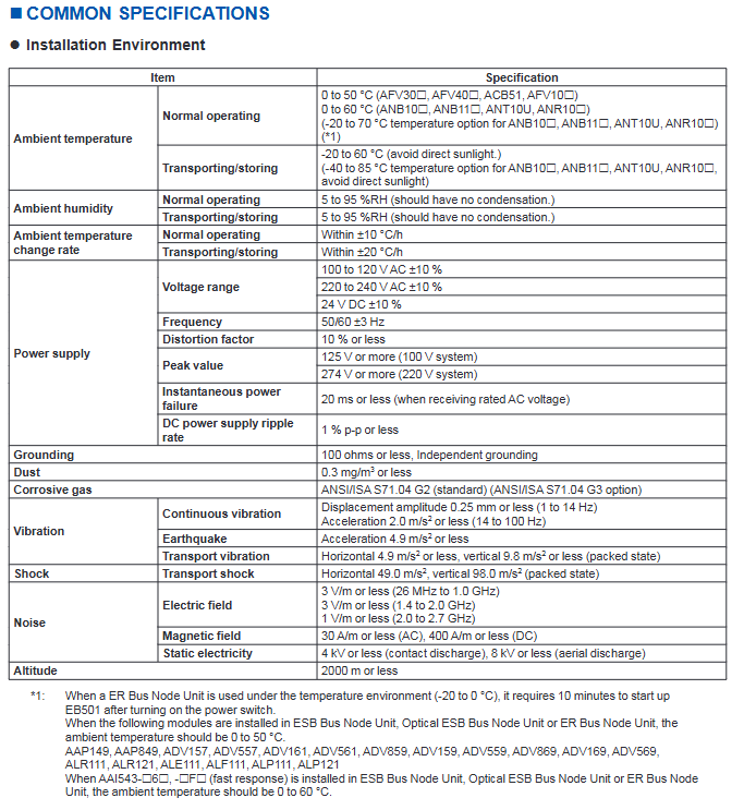
Environmental and power specifications
1. Environmental parameters
Project Standard Scope Extension Options (Partial Modules)
Working temperature 0-50 ℃ (FCU), 0-60 ℃ (node unit) -20-70 ℃ (ANB10 /ANB11 /ANT10U/ANR10 )
Storage temperature -20-60 ℃ -40-85 ℃ (expansion option)
Relative humidity 5-95% RH (non condensing) 5-95% RH (non condensing)
Temperature change rate ± 10 ℃/h (working), ± 20 ℃/h (storage)-
Altitude ≤ 2000m-
Vibration 1-14Hz (0.25mm amplitude), 14-100Hz (2.0m/s ²)-
2. Power parameters
Power type, voltage range, frequency/ripple, instantaneous power-off tolerance
AC power supply 100-120V AC ± 10%, 220-240V AC ± 10% 50/60Hz ± 3Hz, distortion rate ≤ 10% ≤ 20ms
DC power supply 24V DC ± 10% ripple ≤ 1% p-p-
The grounding requirement is independent grounding, with a grounding resistance of ≤ 100 Ω —
Installation restrictions and connection methods
1. Module installation restrictions
Power capacity limit:
Non hazardous area: Node unit module factor B sum ≤ 100;
Dangerous zone (ANB10 - E): total factor B ≤ 88;
Dual redundant FCU (AFV10D/AFV30D): Factor A sum ≤ 5, Factor A+B sum ≤ 65.
Temperature related restrictions:
In an environment of 60-70 ℃, each node can install up to 4 I/O modules, and slots need to be left empty between modules;
AAP149, ADV157 and other modules only support 0-50 ℃, while AAI543- 6 (quick response) supports 0-60 ℃.
Safety distance limit:
The distance between the built-in isolation barrier module and other modules is ≥ 50mm, and an insulation partition (T9083NA/T9083ND) needs to be installed;
AAT141 (thermocouple input) needs to be kept away from the heat source, and only specific modules (such as AAT145, AAR181) can be installed adjacent to it.
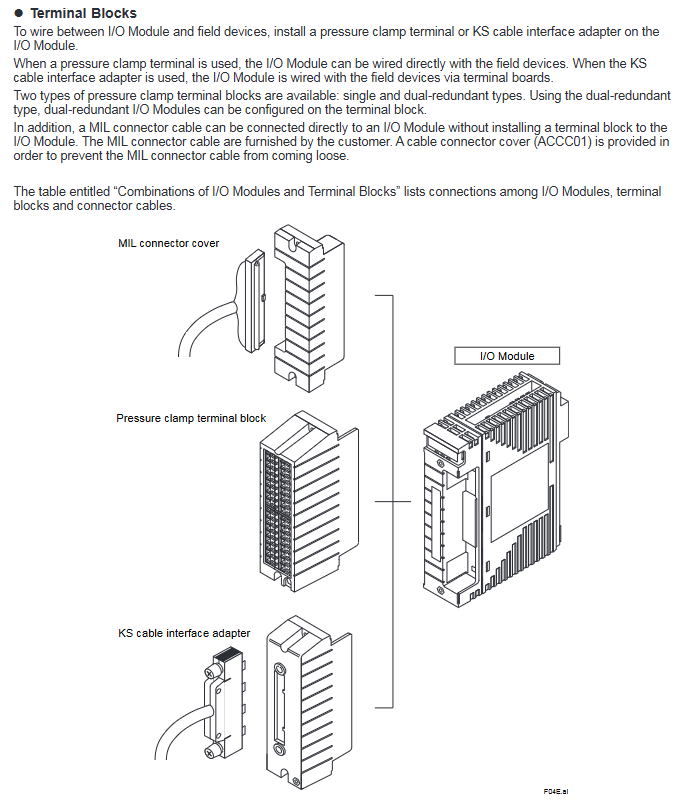
2. Signal connection method
Connection type applicable module media requirements representative accessories
Most analog/digital modules with pressure clamp terminals have a conductor cross-sectional area of ≤ 1.25mm ². ATA4S (single redundancy) and ATA4D (double redundancy) are available
Special cable compatible with ST series module Yokogawa special cable (such as AKB331) ATK4A adapter, KS1 cable
MIL connector cable specific analog module (such as AAI141), customer provided, requires cable connector cover (ACCC01) D-sub 9-pin, M4 terminal block
3. Requirements for dual redundancy configuration
I/O modules need to be installed in adjacent slots (IO1-IO2, IO3-IO4, etc.);
A dual redundant terminal block (such as ATA4D) connects two adjacent I/O modules;
The dual redundancy of communication modules (such as ALR111) needs to be configured according to communication functions, with a maximum of 8 pairs per FCU.
Compliance standards
Safety standards: CSA, CE Marking, EAC Marking (excluding some modules such as ADR541);
EMC standards: CE Marking, EAC Marking, RCM, KC Marking (excluding built-in isolation barrier modules);
Explosion proof standard: CSA Non-Incendive、FM Non-Incendive、Type n、Type i( intrinsic safety)、FM intrinsic safety;
Environmental standards: ANSI/ISA S71.04 G2 (standard), G3 (option).
Key issues
Question 1: What are the core differences between the three communication buses (ESB/Optical ESB/ER) supported by the FIO system? What are the applicable scenarios?
answer:
Core Differences:
Comparison Dimension ESB Bus Optical ESB Bus ER Bus
Transmission rate 128Mbps 128Mbps 10Mbps
Transmission medium specific cable (YCB301) Single mode fiber coaxial cable (YCB141/YCB311)
Maximum distance 10m 50km (relay) 185m (YCB141)
Compatible with FCU AFV10 /AFV30 /AFv40 AFV30 /AFv40 AFV10
Applicable scenarios:
ESB bus: close range (≤ 10m), high transmission rate requirements, suitable for connecting AFV full series FCUs and node units;
Optical ESB bus: Long distance (≤ 50km), anti-interference requirements, suitable for long-distance node expansion of AFV30 /AFV40 ;
ER bus: Medium distance (≤ 185m), low-cost requirement, only applicable to standard FCS configuration of AFV10 .
Question 2: What conditions must be met for the dual redundancy configuration of FIO system I/O modules? How to ensure the effectiveness of redundancy?
answer:
Configuration conditions:
Module installation: I/O modules need to be installed in pairs in adjacent slots (IO1-IO2, IO3-IO4, etc.), with dual redundant terminal blocks (such as ATA4D) connected accordingly;
Module model: It is necessary to use I/O modules that support dual redundancy (modules marked with “X” in the document, such as ADV151 and AAI543), and some modules (such as ADV141) do not support dual redundancy;
Node unit: Dual redundant node units (ANB10D/ANB11D/ANR10D) are required, and single redundant node units (ANB10S, etc.) cannot achieve module dual redundancy;
Bus configuration: The ESB/optical ESB/ER bus needs to enable dual redundancy function, and the FCU needs to install the corresponding dual redundancy coupling module (such as EC402).
Effectiveness guarantee:
The control side and backup side module models and software versions are consistent;
The signal connection needs to be established through dual redundant terminal blocks to ensure signal synchronization on both sides;
Verify the redundant switching function (dual redundant FCU scenario) through APC (Automatic Phase Control) after installation.
Question 3: What module selection and installation requirements should be focused on when installing FIO systems in hazardous environments (explosion-proof requirements)?
answer:
Module selection requirements:
Prioritize selecting modules that support explosion-proof ratings: Type i (intrinsic safety) or Type n (spark free), such as ASI133 (Type i), AAI543 (Type n);
Dangerous areas require the use of I/O modules with built-in isolation barriers (such as ASI133, ASD143) to avoid external isolation barrier configurations;
Exclude modules that do not support explosion-proof, such as ADR541 which does not support Type n and ARS series modules which do not support CE/AAC explosion-proof standards.
Installation requirements:
Distance isolation: The distance between the built-in isolation barrier module and the non intrinsic safety module is ≥ 50mm, and an insulation partition (ANB10 using T9083NA, AFV10 /AFV30 using T9083ND) needs to be installed;
Power restriction: The total factor B of the hazardous area node unit module is ≤ 80 (ANB10 - F) or ≤ 88 (ANB10 - E);
Environmental adaptation: Select G3 level corrosive gas protection module, temperature range follows -20-60 ℃ (extended option);
Wiring specification: Use explosion-proof certified cables with a conductor cross-sectional area of ≤ 1.25mm ², connected from the CH1 terminal.
Leave a comment
Your email address will not be published. Required fields are marked *