Core features and structure of the product
1. Core design and maintenance free advantages
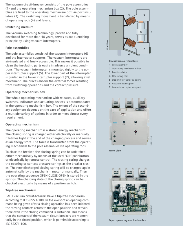
Vacuum arc extinguishing system:
The arc extinguishing chamber adopts air insulation, which can be freely contacted and the insulation components are easy to clean in harsh environments;
The upper bracket of the arc extinguishing chamber is fixed, the lower bracket is axially guided, and the supporting components absorb external forces and contact pressure during opening and closing;
Maintenance free cycle: Under normal conditions (IEC 62271-1), it supports 10000 operating cycles without lubrication or adjustment.
Spring energy storage operating mechanism:
Energy storage method: electric energy storage (standard, motor voltage 24-240V DC/AC) or manual energy storage (with dedicated handle, order number 3AX15 30-4A/B/C);
Opening and closing control: remote electric (closing soleoid voltage 24-240V DC/AC), local mechanical/electric (to prevent accidental closing, switch equipment interlock needs to be connected);
Operation sequence: Supports standard sequence O-3min-CO-3min-CO (normal current), CO-30min-CO (short-circuit current), and some models support O-0.3s-CO-15s-CO (≤ 31.5kA).
2. Key functions and safety design
Free release mechanism: in accordance with IEC 62271-100, when receiving a disconnection command during the closing process, the contact immediately returns to the disconnection position and remains in place to avoid continuous disconnection (“pump effect”);
Interlocking system:
Electrical interlocking: The auxiliary contacts of the circuit breaker control the electromagnetic lock of the isolation switch, which can only be operated when the circuit breaker is opened;
Mechanical interlocking: detecting the position of the circuit breaker through sensors to prevent on load opening and closing, and adapting to drawer type components;
Release signal control: When the NO contact is opened, it instantly closes, triggering the alarm system. Local control requires a series cut-off switch (distinguishing between automatic/manual opening).
Technical parameters and environmental adaptation
1. Core electrical parameters (classified by voltage level)
Voltage level Rated lightning impulse withstand voltage (kV) Rated short-time power frequency withstand voltage (kV) Rated short-circuit breaking current (kA) Rated normal current (A) Pole distance (mm)
7.2kV 60/75 20/32 50/63 1250-4000 210/275
12kV 75/95 28/36 50/63 1250-4000 210/275
17.5kV 95/110 36/42 50/63/72 3150-8000 275/300
24kV 125/145 50/60 50/63/72 3150-8000 275/300
36kV 170/185/195 70/85/95 31.5/40 1250-4000 350
40.5kV 185/195 85/95 31.5/40 1250-4000 350
2. Environmental and installation restrictions
Climate environment: Complies with IEC 60721-3-3, with specific levels as follows:
Key requirements for environmental type level
Climate environment 3K4 low temperature -5 ℃, humidity ≤ 95%/day, ≤ 90%/month
Biological environment 3B1 is free from mold and insect erosion
Mechanical environment 3M2 anti vibration and impact
Chemical active substance 3C2 is resistant to slightly corrosive gases (without freezing/wind blown precipitation)
Mechanical active substance 3S2 requires regular cleaning of insulation components
Elevation and insulation correction:
When the reference altitude is 1000m, the insulation level needs to be corrected according to the altitude coefficient K a, with the formula: U ≥ U 0 × K a; Example: At 2500m, K a=1.2. If a 75kV lightning impulse withstand voltage is required, a 90kV reference insulation level should be selected.
Current carrying capacity: The reference temperature is 40 ℃ (for open type switchgear), and the rating can be increased when the temperature is below 40 ℃. For example, the carrying current of 6300A can be increased by about 15% at 20 ℃ (refer to the current temperature curve in the document).
Selection and Configuration Rules
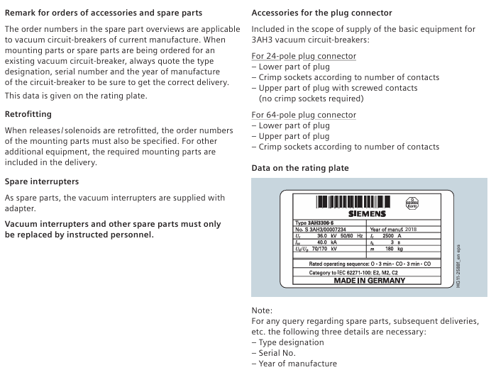
1. Order number structure (16 digits)
Main circuit section (4-8 bits): Define voltage, short-circuit breaking current, rated current, pole spacing, for example:
3AH3 305-6:3 (main group), A (subgroup), H (series), 3 (version), 305-6 (36kV, 40kA, 2500A, 350mm pole spacing);
Secondary equipment section (bits 9-16): Define the combination of release devices, operating voltage, and auxiliary switches, for example:
9-position (release): A (1 shunt release), M (2 shunt releases+1 undervoltage release);
10 positions (closed soleoid): B (24V DC), F (220V DC), K (230V AC);
Option code: End with “- Z” and add a 3-digit code (e.g. Z A20:64 pole plug gold-plated).
2. Core options and auxiliary equipment
Option Category Model/Code Function Description Applicable Scenarios
Automatic tripping device with shunt release (connected to protective relay, 24-240V DC/AC) for overcurrent protection
When the undervoltage release voltage is less than 35% of the rated value, the circuit breaker (24-240V DC/AC) provides abnormal voltage protection
Current transformer operation release without auxiliary power supply, time division switch (0.5/1A rated current), remote and no power supply scenario
Auxiliary switch 6NO+6NC standard, providing regular control requirements for opening and closing status signals
12NO+12NC extended contacts, suitable for complex interlocking multi loop control
Connection interface 24 pole terminal block regular wiring (no plug) fixed installation
64 pole plug for quick insertion and removal, some interfaces can be customized with drawer style switch devices
Additional function Z A30 anti condensation heating (230V AC/50W) for high humidity environment
Z W70 warranty extended to 24 months for critical equipment
Z A70 3AH37 (5000A+) horizontal installation suitable for horizontal installation scenarios
3. Special configuration of generator circuit breaker (IEC/IEEE 62271-37-013)
Additional testing requirements:
Generator side fault: withstand high DC component (130%), no current zero crossing point;
System side fault: higher TRV rise rate, higher test voltage;
Split phase design:
Single pole independent packaging, suitable for 12500A/100kA scenarios, supports parallel operation;
Technical parameter example (17.5kV): Short circuit breaking current 50-90kA, DC component 45-130%, asymmetric breaking current 52-146kA.
Application and maintenance
1. Typical application scenarios
Industrial power distribution: Factory medium voltage power distribution system (high load current 6300A);
Generator protection: 3AH37/38 series (compatible with 17.5/24kV generators, capable of withstanding high DC components);
Special industries: refineries, extruders (harsh environments, compatible with 3C2 grade);
**Retrofit project * *: Replace compressed air generator circuit breakers (6kV, 86.5kA, 3500A).
2. Maintenance and Accessories
Maintenance free range: Within 10000 operating cycles, no lubrication or adjustment is required, only the insulation components need to be cleaned;
Key accessories:
Accessory Name Order Number Usage
Operating handle 3AX15 30-4B manual energy storage
Replacement of vacuum arc extinguishing chamber 3AY17 15-2J 3AH3228-2/6/7 model
Auxiliary switch cable bundle 3AX11 34-2D 64 pole plug wiring (10 wires)
Lubricating grease 3AX11 33-3H Special scenario bearing lubrication (180g Kl ü ber)
Warranty and documentation:
Standard warranty: 12 months, optional Z W70 (24 months), Z W71 (36 months);
Documents: Operating instructions (German/English/French/Spanish), dimension drawings (such as A7E32500008).
Technical data and operational characteristics
1. Operation time (under rated secondary voltage)
Operation type, time parameter value
Closing time from command to contact closure < 75ms
Opening time: 1 shunt release<60ms
2/3 release devices < 55ms
The duration of the arc after the ignition time is opened is less than 15ms
The disconnection time of one shunt release (disconnection+arcing) is less than 75ms
2/3 release devices < 70ms
Energy storage time: Electric energy storage (full capacity) < 15s
2. Release power consumption (reference value)
Release type DC power consumption (W) AC power consumption (VA) Operating range
Closing soleoid 140 140 85-110% rated voltage (DC/AC)
1st shunt release 140 140 70-110% rated voltage (DC), 85-110% (AC)
2nd shunt release 60 60 70-110% rated voltage (DC), 85-110% (AC)
Undervoltage release 20 20 35-0% rated voltage (DC/AC)
Current Transformer Operating Release -10 90-110% Rated Current (AC)
Leave a comment
Your email address will not be published. Required fields are marked *