Product basic information
1. Product positioning and core functions
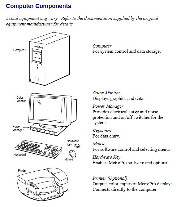
MicroLUPI is a micro aperture laser unequal path interferometer (LUPI) developed by Zygo. Based on phase-shift interferometry technology, it focuses on non-contact high-speed automated measurement of micro optical components, which can accurately detect the surface morphology and curvature radius of spherical/planar optical components. It also supports batch measurement of optical arrays and is equipped with a 3mm diameter collimated measurement beam. The core components include a granite base, a stable gantry column, an electric focusing mechanism, and an X/Y electric stage.
2. Optional configurations
Configuration items, specific parameters/instructions
Objective 50X SLWD (ultra long working distance), NA value 0.45 (usable 0.38); 100X SLWD, NA value 0.73
Laser wavelength standard 632.8nm, customizable blue to near-infrared band
Z-axis digital indicator incremental Z-axis length gauge, used for high-precision curvature radius measurement (standard on some models)
Vacuum suction cup suitable for 3/4/6 inch wafer fixed stage vacuum suction cup
3. Key technical parameters
Laser: Stable frequency helium neon laser (fiber output), power ≤ 1mW, coherence length ≥ 10m
Motion system: The X/Y stage and Z-axis focusing are both driven by DC brushless micro stepper motors, with a stroke of 152mm (6 inches), a resolution of 0.1 μ m (4 μ in), and a maximum speed of 12.7mm/s (0.5in/s)
Imaging and Observation: Maximum 640 × 480 pixel camera, 9-inch monochrome video monitor for real-time display, supports manual/auto focus
Environmental requirements: temperature 15-30 ℃ (59-86 ° F), temperature change rate<1.0 ℃/15 minutes, humidity 5% -95% (no condensation), vibration isolation frequency 1-120Hz
Laser safety: Complies with DHHS Class II laser standards, emits only visible red light, and has no visible radiation
Installation and initialization
1. Preparation before installation
Environmental requirements: Concrete floor should be used to reduce vibration, avoid air conditioning/fan direct blowing causing airflow disturbance, and stay away from optical pollution sources such as smoke and dust
**Utility requirements * *: 100-240VAC 50/60Hz power supply (with grounding), vibration isolation table requires ≥ 60psi compressed air (1/4 inch interface), vacuum suction cup requires 1/8 inch NPT interface vacuum source
Installation restriction: The device must be operated by Zygo trained personnel, and after opening the box, it must be left to stand in the installation environment for 24 hours to adapt to temperature and humidity
2. Core installation steps
Position the vibration isolation system and workbench, and install the granite base, column, Z-axis stage, and MicroLUPI machine head in sequence
Connect the laser power supply, motion controller, motor driver and other cables, ensure that the hardware key is connected to the parallel port of the computer, and the controller board cables are correctly connected
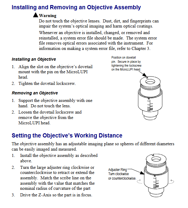
Install the objective lens (align with the dovetail groove pin and tighten the locking screw), adjust the working distance of the objective lens (match the engraved line according to the nominal curvature radius of the measured part)
Calibrate the machine head and X/Y stage: After removing the objective lens, place the optical flat mirror and adjust the X/Y axis adjustment screws to minimize the number of interference fringes
3. Startup initialization process
Turn on the laser power with the key and wait for the “Locked” indicator light to turn on; Turn on all components through the power manager
Log in to Windows NT on the computer (default username “zygo”), open MetroPro software and load MicroLUPI.app application
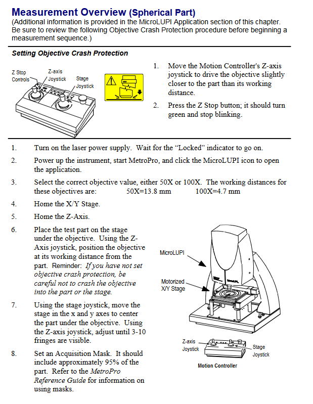
Perform X/Y stage and Z-axis “home” operation, set Z-axis collision protection (move the objective lens to a slightly smaller distance than the working distance, press the Z Stop button until the green light stays on)
Measurement operation process
1. Basic operation preparation
Controller usage: Adjust the height of the objective lens through the Z-axis joystick (push/pull to control lifting, deflection amplitude to control speed), move the stage with the X/Y joystick, and the emergency stop button (Motion Stop) can interrupt all movements
Light intensity adjustment: Press F4 to open the light intensity window, adjust all indicators to green through the numeric keypad (to avoid saturation and data loss), and F5 can automatically set the light intensity
2. System error calibration (key steps)
Calibration purpose: To eliminate inherent errors in the optical system of the instrument and improve measurement accuracy, recalibration is required after replacing the objective lens, adjusting the camera mode/phase resolution, or changing the ambient temperature
Operation steps:
Place the Zygo standard reference ball (avoid touching the optical surface), adjust X/Y/Z to align the center of the ball and hide the stripes
Set the average number of phase measurements in the measurement control window (recommended to be 3 times that of regular measurements, with a minimum of 8 times), and turn off “Subtext Sys Error”
After measuring with F1, save the data (named in a format such as “SysErrLN1x. dat” to distinguish between camera mode and phase resolution). During subsequent measurements, enable “Subtext Sys Error” and load the corresponding error file
3. Typical measurement scenarios (curvature radius of spherical parts)
Select the matching objective lens (50X working distance 13.8mm, 100X working distance 4.7mm), place the test piece and center it through the stage control lever
Enable AutoNULL (optional Power/Focus mode), set Lateral Pass Limit and Power/Focus Pass Limit
Click on “Auto Calibrate” to calibrate the X/Y/Z calibration coefficients (the fitting quality should be close to 1), and execute AutoNULL to optimize the stripes
Start measuring with F1, and the system automatically collects “cat’s eye” and “confocal” data to calculate the curvature radius; Batch measurement can create rectangular/circular measurement paths through the “Pattern Editor” (setting parameters such as row and column count, spacing, etc.)
Maintenance and after-sales service
1. Daily maintenance
Cleaning of optical components:
Dust: Blow off with compressed air, and wipe the remaining dust in one direction with lens paper dipped in isopropanol/methanol
Fingerprints/oil stains: Dip in 1% neutral soap solution to wipe, then use distilled water to remove residue, and finally finish with alcohol (do not reuse wiping materials)
Mechanical and electronic components: Use a soft cloth dipped in mild cleaner to wipe the external surface, and do not disassemble components such as motor drivers and controllers (no user repairable parts)
2. Malfunctions and after-sales service
Warranty Policy: The equipment comes with a 1-year warranty from the date of shipment (for material/process defects), standard support is provided for 5 years after discontinuation, and “best effort” support is provided thereafter; The warranty service includes free repair/replacement (with transportation, cleaning, and calibration fees to be borne), a 90 day warranty for replacement parts, or the remaining warranty period of the original warranty (whichever is longer)
Return requirement: Unused and well packaged products can be returned within 30 days, with a 20% restocking fee charged; Customized products cannot be returned, and returns must first obtain a Return Authorization (RA) number
Technical Support: In North America, you can call (800) 994-6669 (Monday to Friday 8:00-17:00 EST). In other regions, you need to provide the device model, serial number, and software version to contact the local agent
Safety and Compliance
1. Laser safety operation
Do not stare directly at the laser beam or its strong light reflection. When the device is turned on, ensure that the laser exit is unobstructed
Laser emission control: The key switch on the laser power supply is the main control (no radiation after turning off), and the “Emission Indicator” light is on to indicate that there may be laser output
Safety signs: The equipment is labeled with Class II laser warning signs (“CAUTION LASER RADATION DO NOT STARE IN BEAM”), exit port signs, non interlocking protective shell signs, etc., which must be kept clear and visible
2. Compliance certification
Compliant with the EU EMC Directive and Low Voltage Directive, meeting standards such as EN 55011 (ISM equipment RF interference), EN 61010-1 (safety of measuring equipment), EN 60825-1 (laser safety), etc
Having CE certification and JISO 9001 certification, the relevant conformity declaration is archived at Zygo’s US headquarters
Leave a comment
Your email address will not be published. Required fields are marked *