Product Overview
Product positioning and types
VT-HNC100 is a programmable NC controller developed by Bosch Rexroth AG, specifically designed for closed-loop control shafts. It meets the specific requirements of hydraulic drive closed-loop control and can also be used for electric drive control. The products are divided into two main types:
VT-HNC100-1: Single axis version, supports 8 or 24 digital inputs/outputs
VT-HNC100-2: Dual axis version, supports 16 digital inputs/outputs
Both belong to the 2X component series (20-29 series, with unchanged installation and connection dimensions), comply with the EC directive (CE mark), and exhibit excellent anti-interference, mechanical anti vibration and shock resistance, and weather resistance, making them suitable for harsh industrial environments.
Application scenarios
Widely used in the following industrial equipment:
Machine tools, plastic processing machines, special machinery
Presses
Transfer lines
Rail bound vehicles
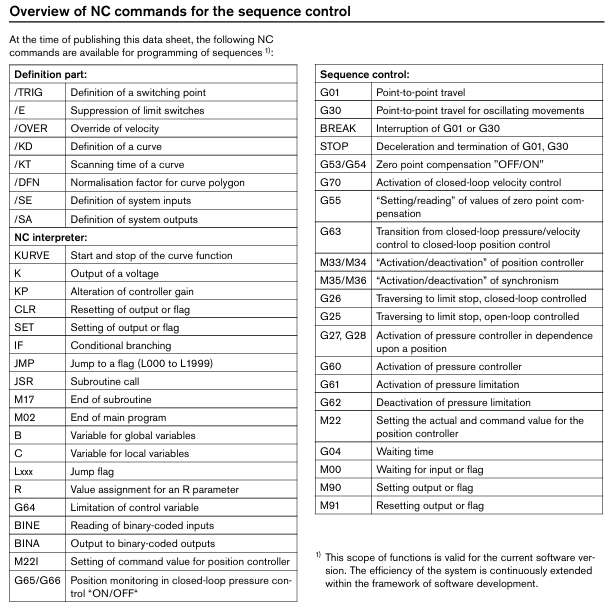
Core functions and operations
(1) Programming and Operations
Programming method
User programming through PC, using NC language with subroutine technology and conditional jump
Support writing exclusive NC programs for functional sequences
Multiple HNC100 parameters can be set through the local CAN bus
Operations Management
Implementing convenient data management on PC
Quickly modify data through handheld control box BB-3 (reference RE 29798) or control panel BF-1 (reference RE 29794)
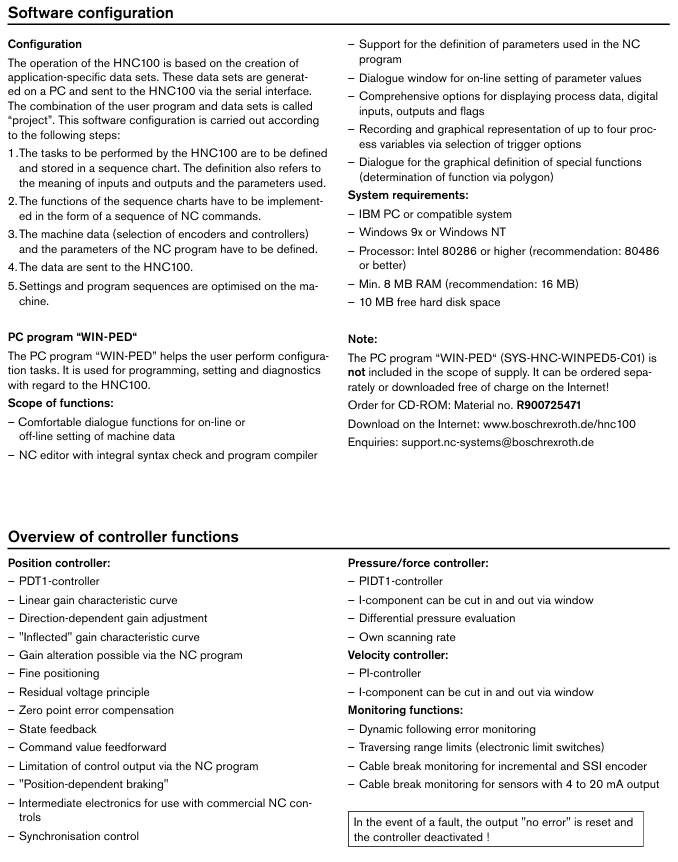
Software Configuration Tool – WIN-PED
It needs to be ordered separately or downloaded for free from the official website (material number R900725471, download address: www.boschrexroth. de/hnc100). The functions include:
Convenient dialogue function for online/offline setting of machine tool data
NC editor with syntax check and program compiler
Support the definition of parameters used in NC programs
Dialogue window for setting parameter values online
Multiple options for displaying process data, digital I/O, and flag bits
Record and graphically display up to 4 process variables (with selectable trigger options)
Graphically defining special functions (determined by polygons)
The operating system requirements are: IBM PC or compatible machine, Windows 9x/NT, Intel 80286 and above processor (recommended 80486), at least 8MB RAM (recommended 16MB), 10MB free hard disk space.
(2) Core functions of the controller
Key functions of controller type
Position Controller (PDT1 Controller) – Linear Gain Characteristic Curve, Direction Dependent Gain Adjustment
-The “bending” gain characteristic curve can be modified by NC program to adjust the gain
-Fine positioning, residual voltage principle, zero error compensation
-State feedback, instruction value feedforward
-Limit control output through NC program and support ‘position dependent braking’
-2-axis synchronous control
Pressure/Force Controller (PIDT1 Controller) – Component I can be cut in and out through a window
-Differential pressure evaluation function
-Independent scanning rate
Speed controller (PI controller) – I component can be cut in and out through a window
Monitoring Function – Dynamic Follow Error Monitoring
-Travel range limit (electronic limit switch)
-Incremental and SSI encoder disconnection monitoring
-4-20mA output sensor disconnection monitoring
-Reset the ‘error free’ output and disable the controller in case of malfunction
(3) Process interface
Support multiple interface methods for communication with PLC:
Digital input/output: single axis version with 8 or 24 channels, dual axis version with 16 channels
Fieldbus: Profibus DP, CANopen, INTERBUS-S, SERCOS (note: interface cables are not included in the supply scope, 3-meter cables can be ordered separately, other lengths need to be consulted); Profibus DP requires an additional order for plug 6ES7972-0BA20-0XA0, material number R900050152)Analog signal, serial interface
Technical parameters
(1) Basic electrical and hardware parameters
Parameter category specific specifications
Working voltage (U ₀) 18-36 VDC
Power consumption (P_int) 8 W (including connected sensor/actuator power supply)
Processor 16/32-bit MC68376
Storage capacity Flash EPROM: 1 MB; EEPROM:8 KB; RAM (Main Memory): 256 KB
Position sensor power supply U ₀ or+5 VDC ± 5%, maximum 200 mA
The maximum voltage of all input signals is U ₀ -1 V (signal without photoelectric isolation)
(2) Simulate input/output parameters
Type and specification
Analog input – Voltage input (differential): 4-channel, input voltage ± 10V (maximum ± 15V), input resistance 200k Ω± 2%, resolution 5mV, nonlinearity<10mV
-Current input: 4-channel, input current 4-20mA, input resistance 100 Ω± 0.2%, resolution 5 μ A
-Impedance input: 4-channel, input voltage ± 10V, input resistance>10M Ω, resolution 5mV
Analog output – Voltage output: 4 channels, output voltage ± 10V (maximum ± 10.7V), output current ± 10mA, minimum load 1k Ω
-Current output: 2-channel, standardized 4-20mA, non standardized ± 23mA, maximum load 500 Ω
-Residual ripple: ± 60mV (no noise), resolution 1.25mV
(3) Digital and Communication Parameters
Parameter category specific specifications
Serial interface standard: RS232 (9.6 KBaud); Optional: Profibus DP (maximum 12 MBaud), CANopen, INTERBUS-S
Switch input 8/16/24 channels, logic level: low level (log 0) ≤ 5V, high level (log 1) ≥ 10V (up to U ₀), input resistance 3k Ω± 10%, supports maximum 1.5mm ² flexible wire
Switch output 8/16/24 channels, logic level: low level (log 0) ≤ 2V, high level (log 1) ≤ U ₀, maximum output current 50mA, supports maximum 1.5mm ² flexible wire
Digital Position Sensor – Incremental (TTL Output): Input voltage 0-1V/2.8-5.5V, input current -0.8mA (0V)/0.8mA (5V), maximum frequency 250kHz (Ua1)
-SSI sensor: Gray code, maximum data width of 28 bits, TTL line receiver/driver
(4) Environmental and physical parameters
Parameter category specific specifications
Working temperature range 0-50 ° C
Storage temperature range -20-+70 ° C
Dimensions (W × H × D) – VT-HNC100-1-2X/-08:71 × 155 × 204 mm
-VT-HNC100-2-2X/. -16, VT-HNC100-1-2X/. -24: 106.5 × 155 × 204 mm
Weight – VT-HNC100-1-2X/-08:1.0 kg
– VT-HNC100-2-2X/.-16、VT-HNC100-1-2X/.-24:1.2 kg
Pin allocation
The pin definitions vary among different models, and the core interface pins are as follows (taking key models as an example):
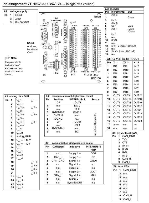
(1) VT-HNC100-1-2X/. -08 (single axis version)
Interface Name Key Pin Function
X4 (COM/local CAN) pin 1: CAN_GND; 8-pin: CAN_SH; 9-foot: CAN_L; 4-pin: 24VN; 5-pin: 0VN
X3 (encoder) pin 3: Ua0; 5 feet: Ua1; 8 feet: Ua2; 12 pins: 5VTTL (maximum 150mA); 14 feet: 24VN (maximum 200mA)
X6 (power supply) pin 1: Shield; Pin 2: GND; 3-pin: 18-36VDC
X2 (analog IN/OUT) 1 pin: Uin1+/In1-; 12 feet: Uref=+10V; 13 feet: Uref=-10V; 14 feet: Iout1; 15 feet: Uout1
X1 (digital IN/OUT) pins 1-8: IN1-IN8; Feet 9-16: OUT1-OUT8; 17 feet:/error
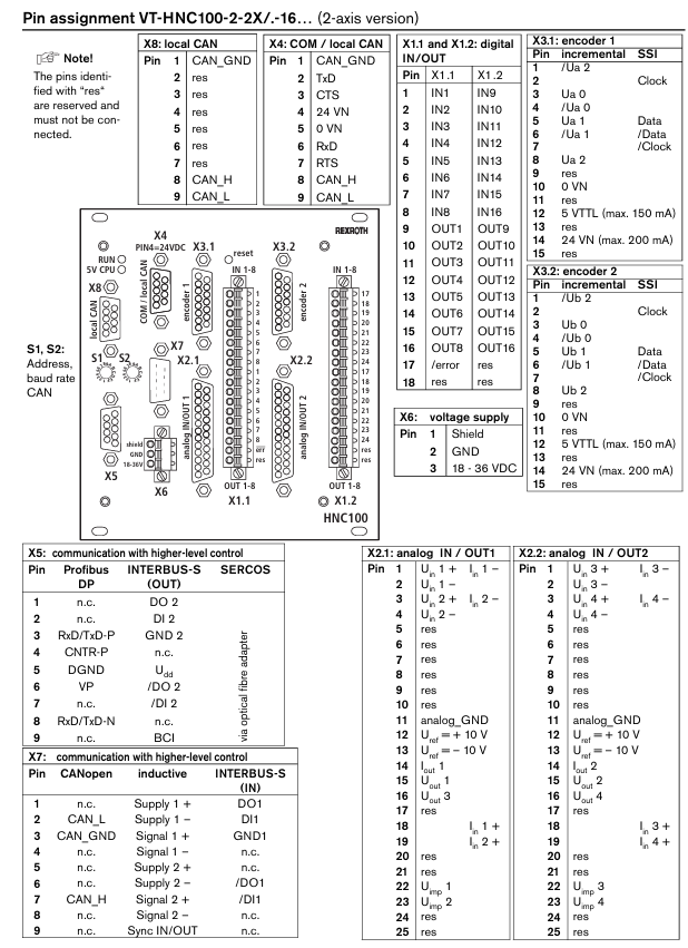
(2) VT-HNC100-2-2X/. -16 (Dual axis version)
The digital IN/OUT is divided into X1.1 (IN1-IN8, OUT1-OUT8) and X1.2 (IN9-IN16, OUT9-OUT16)
The encoder interface is divided into X3.1 (axis 1) and X3.2 (axis 2), and the X3.2 pin function corresponds to X3.1 (such as 1-pin:/Ub2, 3-pin: Ub0, etc.)
The simulation of IN/OUT is divided into X2.1 (axis 1) and X2.2 (axis 2), with functions similar to the single axis version
Preferred model
Bosch Rexroth recommends the following VT-HNC100 models, with specific information as shown in the table below:
Model Material Number
VT-HNC100–1–2X/W-08-0-0 R900955334
VT-HNC100–1–2X/W-08-I-0 R900955332
VT-HNC100–1–2X/W-08-P-0 R900958999
VT-HNC100–1–2X/W–08–C–0 R900959000
Precautions
The pins marked with “res” are reserved pins and cannot be connected
WIN-PED software (SYS-HNC-WINPED5-C01) is not included in the scope of supply and needs to be ordered or downloaded separately
The additional plug required for Profibus DP (6ES7972-0BA20-0XA0) needs to be ordered separately, material number R900050152
For details on environmental simulation tests for EMC (Electromagnetic Compatibility), climate, and mechanical stress, please refer to RE 30131-U (Environmental Compatibility Declaration)
Leave a comment
Your email address will not be published. Required fields are marked *