Module foundation and core characteristics
SKiiP 1213 GB123-2DL V3 is a SKiiP under SEMIKRON ® The 3-series 2-in-1 integrated intelligent power system has high integration and industrial grade reliability, with the following core features:
Core technology: Built in SKiiP technology, using trench insulated gate bipolar transistors (Trench IGBTs) and CAL HD diode technology, balancing efficient switching and low loss;
Integrated components: Equipped with current sensors, temperature sensors, and heat sinks, reducing the need for external accessories and simplifying installation;
Compliance certification: UL certified, document number E63532, meets industrial safety standards.
Typical application scenarios cover fields with high requirements for power control, such as renewable energy, traction systems, elevators, and industrial transmissions (note: MKP capacitors that are compatible with each terminal need to be used).
Key electrical parameters (unless otherwise specified, ambient temperature Ts=25 ℃)
(1) Absolute maximum rated value
Category parameter symbol condition description numerical unit
System VCC working DC link voltage 900 V
Visol DC for 1 second, main terminal to heat sink 4300 V
It (RMS) per AC terminal, terminal temperature<115 ℃ 400 A
IFSM junction temperature Tj=150 ℃, pulse width tp=10ms, sine 180 ° 6900 A
I ² t Tj=150 ℃, tp=10ms (diode) 238 kA ² s
Tstg storage temperature -40~85 ℃
IGBT VCES Tj=25℃ 1200 V
IC Tj=150℃,Ts=25℃ 1145 A
IC Tj=150℃,Ts=70℃ 882 A
ICnom rated current 1200 A
TJ junction temperature (note: -40~150 ℃) -40~150 ℃
Diode VRRM Tj=25 ℃ 1200 V
IF Tj=150℃,Ts=25℃ 925 A
IF Tj=150℃,Ts=70℃ 700 A
IFnom rated forward current 930 A
Tj junction temperature -40~150 ℃
Driver Vs power supply voltage 13~30V
ViH input signal high level voltage 15+0.3 V
VisolPD QPD≤10pC, 1170 V from the primary side to the power end
Dv/dt secondary to primary voltage change rate of 75 kV/μ s
FSW switch frequency 15 kHz
(2) Key characteristic parameters
Category parameter symbol condition description Minimum value Typical value Maximum value Unit
IGBT VCE (sat) IC=600A, Tj=25 ℃ (at the terminal) 1.7-2.1 V
VCE (sat) IC=600A, Tj=125 ℃ (at the terminal) -1.9-V
Eon+Eoff IC=600A,VCC=600V,Tj=125℃ – 221 – mJ
Eon+Eoff IC=600A,VCC=900V,Tj=125℃ – 390 – mJ
Rth (j-s) each IGBT switch, junction to heat sink thermal resistance -0.03 K/W
Diode VF (VEC) IF=600A, Tj=25 ℃ (at the terminal) 1.50-1.80 V
Err IF=600A,VR=600V,Tj=125℃ – 42 – mJ
Err IF=600A,VR=900V,Tj=125℃ – 56 – mJ
Rth (j-s) each diode switch, junction to heat sink thermal resistance -0.058 K/W
Driver Is current formula: 240+k1fsw+k2IAC (k1=29mA/kHz, k2=0.00065mA/A ²) — mA
ITRIPSC overcurrent trip level 1470 1500 1530 A (peak)
Tttrip over temperature trip level 110 115 120 ℃
System Rth (r-a) flow rate=460m ³/h, Ta=25 ℃, altitude 500m -0.0344 K/W
LCE commutation inductor -6- nH
W Weight without heat sink -1.7kg
WH heat sink weight -4.4kg
Isolation and environmental requirements
(1) Isolation coordination (compliant with EN 50178 and IEC 61800-5-1)
Grid voltage: The maximum RMS value of the grounding triangle grid line voltage is 480V+20%, corresponding to an installation altitude of 2000m; the maximum RMS value of the star point grounding grid line voltage is 480V+20%, corresponding to an installation altitude of 5000m;
Transient voltage: The maximum transient peak voltage between the low-voltage circuit and the power grid is 1600V;
Protection level: The heat sink is basically isolated from the power grid, with a protection level of IP00 (compliant with IEC 60529);
Pollution level: molded power part external pollution level 2 (compliant with IEC 60664-1);
Overvoltage category: Grid side overvoltage category III (compliant with IEC 60664-1).
(2) Environmental conditions (compliant with IEC 60721)
Environmental scenario, climate conditions, biological conditions, chemical active substances (excluding salt spray), mechanical active substances, mechanical conditions, pollution of fluids
Storage: 1K2 1B1 1C2 1S1 1M3 (customer customized packaging without declaration)-
Transport 2K2 (extended temperature range -40~85 ℃, shortened operating life near 85 ℃) 2B1 2C1 2S1–
Weather protection fixed use 3K3/1 3B1 3C2 3S1 3M6 (3M7 is feasible but limited by external components)-
Ground installation operation 5K1m 5B1 5C2 5S1 5M3 (no foreign objects/stone impact) 5F1
Ship Environment Operation -6B1 6C2 6S1 6M3-
Other key information
Thermal characteristic chart: including IGBT/diode output characteristics, energy loss (E=f (Ic, VCC)), flow rate and voltage drop/thermal resistance relationship, transient thermal impedance and other charts (as shown in Figure 1-9), which can be used for thermal design and loss calculation;
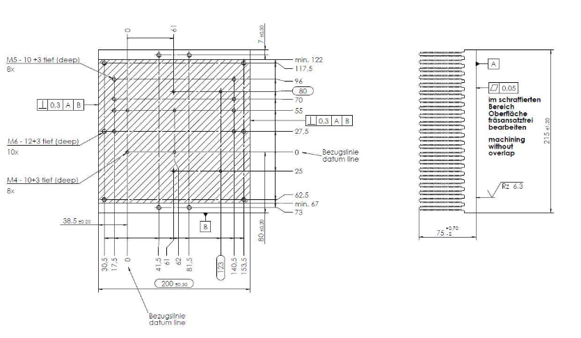
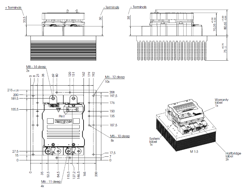
Mechanical dimensions: Provide detailed installation dimensions for modules and heat sinks (such as bolt specifications M4/M5/M6/M8, installation depth, spacing, etc.), which need to be mechanically assembled according to the drawing parameters;
Electrostatic sensitivity: It belongs to electrostatic discharge sensitive devices (ESDS) and should be operated in accordance with the specifications in Chapter 9 of IEC 60747-1;
Usage tip: Component specifications do not represent feature guarantees, and specific application testing is required; Prior written approval from SEMIKRON is required for use in life support equipment, and it is recommended to consult the manufacturer before use.
Leave a comment
Your email address will not be published. Required fields are marked *