Core hardware configuration and performance
1. Processor and cache
Equipped with high-performance MPC7457 PowerPC ® Processor, integrated with 128 bit AltiVec ™ Coprocessor (supporting parallel processing, suitable for vector operation scenarios), with the following core parameters:
Clock frequency: 1.267 GHz, suitable for data intensive applications
Cache system:
Level 1 (L1) cache: 32KB instruction cache+32KB data cache
Level 2 (L2) cache: 512KB (on-chip)
Level 3 cache: 2MB (onboard)
System bus: 133 MHz processor bus, matching processor performance to avoid bus bottlenecks
2. Memory and Storage
Main memory:
Type: Double Data Rate (DDR) ECC SDRAM, supports error checking, improves data reliability
Speed: DDR266 (133 MHz memory bus)
Capacity: Up to 2GB onboard, initially available in two configurations of 512MB/1GB (divided into two memory banks)
Flash memory:
Type: onboard programmable EEPROM, supporting jumper write protection
Capacity: 128MB (divided into two 64MB banks, soldered package, higher stability)
Non volatile memory (NVRAM):
Capacity: 32KB (4KB available for users), equipped with replaceable battery backup
Lifespan: 50 years for storage at 55 ° C, 5 years for use at 25 ° C and 100% duty cycle
Real time clock (TOD): using ST (SGS Thompson) M4T28 device to ensure time synchronization
3. VMEbus and Core Architecture
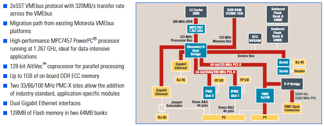
VMEbus protocol: Supports 2eSST (Two Edge Source Synchronous Transfer) protocol, with an actual transfer rate of 320MB/s, which is 8 times higher than traditional VMEbus; Simultaneously compatible with legacy protocols such as ANSI/VITA 1-1994 VME64 and VITA 1.1-1997 extensions
Interface chip: using Tundra Tsi148 ™ VMEbus interface chip, paired with Texas Instruments’ new VMEbus transceiver, supports operation in standard VMEbus backboards, achieving compatibility with existing VME boards and chassis
Host Bridge: Marvel MV64360 Discovery II Host Bridge, supports 133 MHz host bus and 133 MHz DDR memory bus, and provides dual 133 MHz PCI-X buses to connect VME interface chips and PMC expansion slots respectively, ensuring balanced performance of various subsystems
I/O interface and scalability
1. Basic I/O interface
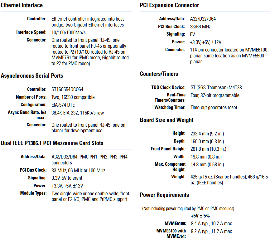
Ethernet:
Controller: Gigabit Ethernet controller integrated into the host bridge, dual interface design
Speed: 10/100/1000 Mb/s adaptive
Connection: One fixed front end (RJ-45), the other can be front end or switched through the P2 interface (10/100 Mb/s routing to MVME761 RJ-45 in IPMC mode, gigabit routing to P2 in PMC mode)
Asynchronous serial port:
Controller: ST16C554DCQ64 (compatible with 16550)
Quantity: 2, supporting EIA-574 DTE configuration
Speed: up to 38.4 Kbps (EIA-232 standard), 115 Kbps (raw mode)
Connection: one front-end (RJ-45), one for development and debugging (onboard header)
Timer: 4 32-bit programmable real-time timers/counters, 1 watchdog timer (timeout triggers system reset, improves system stability)
2. PMC expansion capability
PMC slot: Dual IEEE P1386.1 compatible with PMC-X slot, supporting the following features:
Bus specifications: 32/64 bit address/data, PCI bus frequency 33/66/100 MHz
Power supply:+3.3V,+5V, ± 12V, compatible with 3.3V/5V signals
Module type: Supports 2 single width or 1 dual width PMC/PrPMC (processor PMC) modules, expandable with additional PowerPC processors to achieve multi processor architecture
PCI Expansion: Provides 32/64 bit, 33/66 MHz PCI expansion connectors (114 pins, compatible with MVME5500 position), supports Motorola PMCSpan and other PCI expansion carriers, further expanding I/O capabilities
3. P2 I/O mode and compatibility module
Dual mode configuration: Supports PMC and IPMC P2 I/O modes through jumper cables, continuing the MVME5100/5500 series design and reducing user migration costs:
PMC mode: compatible with MVME2300/2400, MVME5100/5500, P2 interface provides 64 pins for PMC slot 1 and 46 pins for rear I/O in slot 2
IPMC mode: IPMC761/712 modules need to be installed in PMC slot 1, supporting legacy MVME761/712M I/O modules (limited PMC I/O functionality). At this time, some signals in PMC slot 2 are reserved for expanding SCSI
IPMC module function: IPMC761/712 is an optional PMC module that provides rear I/O support to ensure compatibility with previous generation products such as MVME2600/2700
1 single ended Ultra Wide SCSI port
1 parallel port
4 serial ports (IPMC761: 2 asynchronous+2 synchronous/asynchronous; IPMC712: 3 asynchronous+1 synchronous/asynchronous)
Reserve 1 PMC slot for OEM customized expansion
4. Transition Modules
MVME761:
Interface: IEEE 1284 parallel port (HD-36), 10/100BaseTX Ethernet (RJ-45), 2 asynchronous serial ports (DB-9, EIA-574 DTE), 2 synchronous/asynchronous serial ports (HD-26, configurable as EIA-232/EIA-530/V.35/X.21 DCE/DCE through SIM module)
P2 adapter: 3-line adapter supports 8-bit SCSI, 5-line adapter supports 16 bit SCSI and PMC I/O
MVME712M:
Interface: Centronics is compatible with parallel ports (D-36), narrow SCSI ports (8-bit, D-50), 4 synchronous/asynchronous serial ports (DB-25, can be configured as EIA-232 DCE/LTE via jumper)
P2 adapter: 3-line adapter supports 8-bit SCSI; Dedicated 5-line adapter with expandable access to additional user-defined I/O pins for VME64
Software support
1. Firmware Monitor
Firmware name: MOTLoad, residing in Flash memory, providing core functionality:
Power on self-test (POST): comprehensive hardware diagnosis to ensure reliable startup
System initialization: Configure hardware parameters such as processor, memory, I/O interfaces, etc
Operating System Boot: Supports multiple real-time operating systems (RTOS) and kernel booting
Debugging interface: compatible with the “bug” debugging interface of Motorola’s previous generation VME board, reducing development and migration costs
2. Compatible with operating systems
Supports multiple mainstream embedded operating systems, including:
Real time operating system (RTOS): Wind River VxWorks (providing board level support package BSP)
Open source system: Linux (supported by Motorola partners)
Other: Can adapt to various real-time kernels to meet the software requirements of different application scenarios
Physical and Environmental Specifications
1. Size and weight
Size: Compatible with MVME5100 series, single VME slot design:
Board height: 233.4 mm (9.2 inches)
Depth: 160.0 mm (6.3 inches)
Front panel height: 261.8 mm (10.3 inches)
Width: 19.8 mm (0.8 inches)
Maximum component height: 14.8 mm (0.58 inches)
Weight: Scanbe controller version 425 g (15 oz), IEEE controller version 468 g (16.5 oz)
2. Power supply demand
Basic power supply (excluding PMC/IPMC modules):
+5V (± 5%): Typical 8.4 A, maximum 10.2 A
If paired with MVME761 adapter module:+5V typical 9.2 A, maximum 11.2 A
IPMC module additional power supply:
IPMC761/IPMC712:+5V maximum 0.5 A,+3.3V maximum 0.75 A
3. Environmental adaptability
Temperature: Operating temperature 0 ° C to+55 ° C (requires forced air cooling), non operating temperature -40 ° C to+85 ° C
Humidity: Supports 5% -90% in both working and non working states (no condensation, NC)
Vibration: 2G RMS (20-2000 Hz random vibration) in working state, 6G RMS (20-2000 Hz random vibration) in non working state
4. Security and EMC
Safety: All printed circuit boards (PWBs) are manufactured by UL certified manufacturers with a flammability rating of 94V-0, meeting industrial safety standards
Electromagnetic compatibility (EMC):
Launch: Compliant with FCC Part 15 Subpart B (US, Class A, non residential), ICES-003 (Canada, Class A, non residential), EN55022 Class B (EU)
Immunity: Compliant with EN55024 (EU), suitable for industrial, medical and other electromagnetic environment sensitive scenarios
5. Reliability
Mean Time Between Failures (MTBF): 178403 hours (calculated according to Bellcore Standard Version 6, Method 1, Case 3), meeting the requirements of long lifecycle industrial and defense equipment
Ordering information and related products
1. Core module model
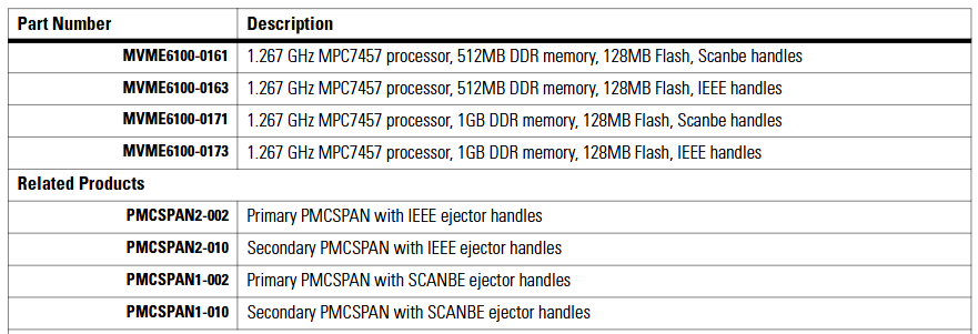
All models offer two options for the front panel: Scanbe controller (suffix – xxx1), IEEE compatible controller (suffix – xxx3), with unified core parameters (1.267 GHz MPC7457, 128MB Flash), with only differences in memory capacity:
Model Memory Capacity Panel Type
MVME6100-0161 512MB DDR Scanbe controller
MVME6100-0163 512MB DDR IEEE controller
MVME6100-0171 1GB DDR Scanbe Handle
MVME6100-0173 1GB DDR IEEE controller
2. Supporting expansion products
PMC extension carrier:
PMCSPN1-002/010: Level 1/Level 2 PMC Extension with Scanbe Pop Up Handle
PMCSP2-002/010: Level 1/Level 2 PMC Extension with IEEE Pop Up Handle
IPMC modules: IPMC761, IPMC712 (providing legacy I/O compatibility)
Adapter modules: MVME761 (with multiple serial ports, Ethernet, SCSI), MVME712M (with serial ports SCSI)
Serial Interface Module (SIM): Supports EIA-232 DCE/LTE, EIA-530 and other configurations, compatible with MVME761
3. Document support
Technical documents can be accessed through Motorola’s official website( http://www.motorola.com/computer/literature )Online viewing, including board installation guides, programmer reference manuals, firmware user manuals, etc., to assist in rapid deployment and development.
Application scenarios and core values
1. Target industry scenario
Defense Aerospace: Suitable for command and control (such as shipborne shielding systems, ground fixed systems, reconnaissance aircraft systems), 320MB/s VME bandwidth, 100 MHz PMC bus eliminates traditional bottlenecks, supports multi processor expansion, and avoids the heat dissipation and I/O management difficulties of multi processor boards
Industrial Automation: Suitable for high-end scenarios such as Semiconductor Processing Equipment (SPE) and Automatic Test Equipment (ATE), AltiVec co processor supports vector computing, dual PMC slots can customize I/O, backward compatibility helps OEMs extend existing design life
Medical imaging: meets the imaging processing requirements of nuclear medicine (NM), positron emission tomography (PET), magnetic resonance imaging (MRI), CT, etc. The 2eSST protocol improves data transmission efficiency, reduces the number of required system boards, and alleviates space limitations
2. Core user value
Investment protection: Compatible with existing VME infrastructure (boards, backboards, software), providing migration paths from MVME2300/2400/2600/2700/5100/5500 to avoid duplicate investments
Balanced performance: processor, memory, VMEbus, PCI-X bus, I/O subsystem performance matching, no obvious bottlenecks, suitable for data intensive and real-time requirements
High reliability: ECC memory, write protected Flash, long-life NVRAM, high MTBF, meeting the stringent requirements for device stability in industrial, defense, and medical fields
Leave a comment
Your email address will not be published. Required fields are marked *