Overview of PLC System
Core composition
Central Processing Unit (CPU): executes instructions and supports standardized programming languages such as Ladder Diagram and Structured Text.
Input/Output Components (I/O):
Digital I/O: Processing switch signals (such as buttons, sensors).
Analog I/O: Processing continuous variables such as temperature and pressure.
Special I/O: Supports high-speed counters, communication modules, etc.
Power module: Provides stable voltage (such as 24VDC/120VAC), with built-in lithium battery to maintain power-off data.
Programming unit: Program development and simulation are carried out through PC software such as PLCLogix and RSLogix.
application area
Petroleum industry: Control the valves, pumps, and sensors of drilling equipment, and use HMI to achieve real-time monitoring.
Glass and cement industry: precise control of raw material ratios and production processes, combined with distributed control systems (DCS) to enhance quality control.
Manufacturing industry: Automated production line control in industries such as automobiles, food, and textiles.
development history
Origin: In 1969, Modicon introduced the first PLC (model 084) to replace relay logic systems.
Evolution: From single control to support Ethernet communication, HMI interface, and modular design, following the IEC 61131-3 programming standard.
Fundamentals of PLC Programming
programming language
Ladder diagram (LD): visually imitates relay circuits, suitable for logic control, using symbols such as normally open/normally closed contacts and coils.
Function Block Diagram (FBD): Representing logical functions (such as timers and counters) in graphical modules for system integration.
Structured Text (ST): A high-level language that is suitable for complex algorithms and supports variable and process control.
Basic instructions and scanning cycle
Scanning cycle: sequentially execute “input reading → program execution → communication processing → output update”, and the scanning time affects real-time performance.
Timer and counter:
TON (Power on Delay): The action is triggered when the timer reaches the preset value.
CTU/CTD (up/down counter): Counting based on input signal changes.
Program control instructions: JMP/LBL jump, SBR/RET subroutine call, optimize program structure.
Data Addressing and Storage
File Addressing System:
I/O File: Stores the physical input/output status (e.g. I: 3/12 represents terminal 12 of input module 3).
Data Files: including bit files (B3), integer files (N7), timer files (T4), etc., supporting addressing by word or bit.
Practical Technology and Optimization
SCADA System Fundamentals
Function: Data collection, network communication, real-time monitoring and control, presenting production status through HMI interface.
Components: Composed of PLC/RTU, sensors, communication networks (such as LAN/WAN), and SCADA software, used for industrial automation management.
Scan time optimization
Strategy:
Place the condition of high frequency being ‘false’ on the left side of the ladder diagram to reduce invalid scanning.
Avoid duplicate instructions and use subroutines (JSR/SBR) and jump instructions (JMP/LBL) to reduce the amount of code running.
Prioritize integer operations and avoid floating-point operations to shorten processing time.
Fault diagnosis and maintenance
Ladder diagram debugging: Test logic through simulation software (such as PLCLogix) and monitor timer/counter status bits (such as DN, EN, TT).
Hardware maintenance: Check the I/O module indicator lights, power supply voltage, and communication connections, and regularly backup programs.
Supplementary content and reference data
Common symbols and devices
Input devices: buttons, limit switches, pressure switches, corresponding ladder symbols (XIC/XIO).
Output devices: relay coils, solenoid valves, motors, symbols include OTE, OTL, etc.
Number Systems and Codes
Binary/Hexadecimal: The internal data storage foundation of PLC, supporting BCD code conversion (such as TOD/FRD instructions).
Gray Code: Adjacent values only change by one bit, used in high-precision scenarios such as encoders to reduce transmission errors.
Core Instruction Set
Position operation: XIC (check for closure), XIO (check for disconnection), OTE (coil output).
Mathematical operations: ADD/SUB/MUL/DIV (addition, subtraction, multiplication, and division), SQRT (square root), trigonometric functions (SIN/COS/TAN).
Data transmission: MOV (data movement), MVM (mask movement), FFL/FFU (FIFO queue operation).
Product positioning and technical specifications
Core functions:
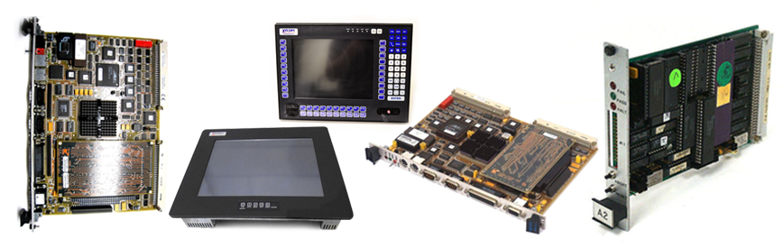
As an HMI device, 4860 A is mainly used for human-machine interaction in industrial automation systems, supporting graphical interface display, parameter settings, and device monitoring.
Technical parameters: 12 inch screen, 115/230V wide voltage input, compatible with 50/60Hz frequency, durable design suitable for industrial environments.
Product positioning and technical specifications
System compatibility:
The communication interface of 4860 A (such as RS-232/422) needs to be matched with the existing PLC or control system. If used for old systems, it is recommended to test protocol compatibility in advance (such as Modbus RTU).
If the original system relies on XYCOM specific software, software compatibility needs to be evaluated when migrating to Pro Face, and some features may need to be redeveloped.
Leave a comment
Your email address will not be published. Required fields are marked *