Call us 24/7uaedcs@163.com
Welcome to the official website of CNIACS Automation Technology Co., Ltd!
Call us 24/7uaedcs@163.com

SCHNEIDER Modicon Quantum Safety PLC

Modicon Quantum Safety PLC is a safety programmable logic controller launched by Schneider Electric, which complies with the IEC 61508 standard and has a certification level of SIL3. Its core revolves around the implementation of safety functions, covering four dimensions: hardware configuration, programming specifications, communication mechanism, and fault diagnosis. It supports two deployment modes: independent/hot standby (HSBY), and ensures functional safety through dual processor execution, redundant I/O design, strict memory partitioning (safe/non restricted area), and dedicated programming software Unity Pro XLS. It is suitable for industrial safety scenarios such as emergency shutdown, burner management, and fire and gas monitoring. At the same time, it provides a complete verification and testing process and maintenance specifications to ensure that the system meets PFD/PFH index requirements in low/high demand modes.

1、 Document Fundamentals and Compliance

(1) Core information of the document

Document Name: Modicon Quantum Safety PLC Safety Reference Manual (Version 10/2017)

Applicable software: Unity Pro XLS V7.0 and above

Target users: Professional technicians with knowledge of functional safety and experience operating Unity Pro

Core objective: To standardize the hardware selection, programming, deployment, and maintenance process of SIL3 level security systems

(2) Compliance and Certification Standards

Standard Name Core Requirements Applicable Scenarios

IEC 61508 (2.0 version) SIL3 level, supports low/high demand mode for general industrial safety systems

IEC 61511 Safety Instrumented Systems (SIS) for Process Industries such as Chemical and Petroleum

EN 54 Fire Detection and Alarm System Fire and Gas Monitoring Scenarios

EN 298 Automatic Gas Burner Control System Burner Management

NFPA 85/86 Boiler Protection Standard Boiler Safety Control

2、 Hardware configuration and core features

(1) Secure CPU module

Model deployment mode core parameter fault detection mechanism

140CPU65160S independently deployed MTBF=600000 hours, supporting 8 secure I/O modules with dual processors (Pentium+application processor) for comparison and memory CRC verification

140CPU67160S hot standby deployment has the same parameters as the standalone version, supporting fiber link synchronization, automatic switching between primary and backup, and application consistency verification

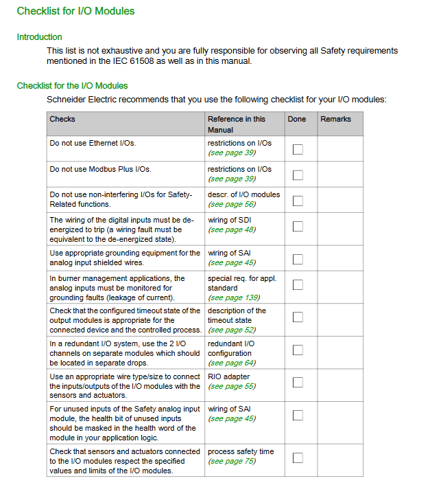
(2) Safety I/O module

Module type, model, core characteristics, diagnostic function

Digital input 140SDI95300S, 32 points, 24Vdc, MTBF=900000 hours, disconnection detection, power monitoring, channel short circuit detection

Digital output 140SDO95300S 32 point, 24Vdc, MTBF=10000000h overload detection, circuit disconnection, timeout state configuration

Analog input 140SAI94000S 8-channel, 4-20mA, MTBF=700000 hours, over range detection, wire breakage detection, measurement linear verification

(3) Auxiliary hardware requirements

Power module: Only supports 140CPS12420 (AC redundancy) and 140CPS22400 (DC redundancy), requiring dual module deployment to ensure availability

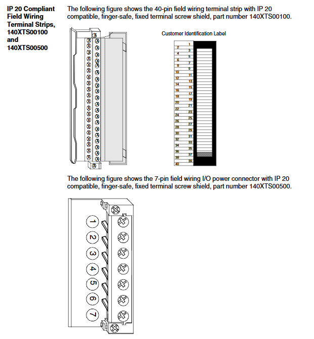
Non interfering modules: including backplane (140XBP series), Ethernet module (140NOE77111), remote I/O adapter (140CRP93200/140CRA93200), not involved in safety functions but must meet compatibility requirements

Wiring specifications: The digital output module needs to be connected in series with a 10A fast fuse, and the analog input needs to be shielded and grounded (recommended STB XSP3000 grounding kit)

3、 Programming standards and software operations

(1) Programming software and language limitations

Unique programming software: Unity Pro XLS (requires secure firmware support)

Language allowed: Function Block Diagram (FBD), Ladder Diagram (LD) only

Disable features: FAST/NTERRUPT tasks, jump statements, ST expressions, derived data types (DDT)

(2) Core programming requirements

Specific requirements and purposes for standardized categories

Task configuration only allows MAST tasks, with a minimum cycle of 20ms to ensure consistency in execution between dual CPUs

The data type only supports basic types such as BOOL/INT/FLOAT+simple arrays to avoid security risks caused by complex data structures

The use of function blocks only allows secure FFB libraries (such as S-AND_ * * *, S-DISIL2, etc.) to ensure the security of logical execution

Memory partition: secure area (write protected), unrestricted area (data transfer only through S2SMOVE-FB), isolated secure/non secure data

(3) Security protection mechanism

Application password: Protect project access, support permission grading (configuration/debugging/maintenance)

Auto lock: After 10 minutes of inactivity (default), the software will be locked and requires a password to unlock

Version stamping: Record the build time when generating binary files for version traceability

Project backup: Regular backup is required (recommended combination of full and incremental backup), with CRC checking for integrity

4、 Operation mode and fault handling

(1) Two operating modes

Mode core feature operation restrictions

Safe mode (default) executes safety functions, prohibits program modification of non downloadable programs, non mandatory variables, and non debuggable

Maintenance mode (temporary) allows program modification, variable forcing, debugging requires unlocking key switch+password, diagnostic results do not automatically execute security actions

(2) Fault diagnosis and handling

CPU failure: When a memory error/inconsistent execution is detected, it enters an error state, and all safety outputs are set to a safe state (power loss). It is necessary to power off and restart, and read the% SW125 error code

I/O module failure: When a channel fails, the single channel is set to a safe state. When a module fails, it automatically restarts and performs a power on self-test. If it fails three times, the module needs to be replaced

Communication failure: When the secure Ethernet communication timeout (configurable) occurs, the HEALTH position is 0, and the receiving end needs to trigger a security action

5、 Communication mechanism

(1) Communication types and restrictions

Core requirements for communication scenario support methods

PC-PLC communication Modbus TCP/RS485/USB requires Unity Pro XLS, verify application password

PLC-PLC communication security requires NTP time synchronization between Ethernet nodes, with unique ID parameters

PLC-HMI communication Modbus TCP/Modbus Plus only allows reading of secure data and writing to restricted non restricted areas

(2) Secure Ethernet point-to-point communication

Synchronization requirement: NTP server polling cycle of 20s, master-slave PLC time difference ≤ 2s

Configuration components: sender end s_WR-ETH FFB, receiver end s_RD-ETH FFB

Timeout configuration: SAFETY VNet ONTROL_TIMEOUT needs to be greater than 2 times (sending cycle+network delay+receiving cycle)

6、 Verification and maintenance

(1) Verification testing requirements

Verification cycle (PTI): up to 10 years, requiring full system testing to be performed in accordance with SIL3 requirements

Verification content: power cycling test, I/O channel verification, safety function triggering test

Document requirements: Keep verification records, fault logs, and project backup files

(2) Maintain standards

Module replacement: Supports hot swapping, and after replacement, a power on self-test (about 30 seconds) needs to be performed

Mandatory operation: Only maintenance mode is allowed, and operation logs need to be recorded and the mandatory operation should be lifted in a timely manner

Firmware upgrade: Only maintenance mode can be executed, and the hot standby system needs to upgrade the backup CPU first

SCHNEIDER Modicon Quantum Automation Series

The Modicon Quantum Automation Series is a hardware reference guide for industrial automation systems launched by Schneider Electric, covering six core sections: system overview, module specifications, installation configuration, power grounding, wiring schemes, and fault codes. It provides detailed technical parameters (voltage/current/accuracy, etc.), LED indicator meanings, wiring diagrams, and configuration requirements for dozens of modules such as power supply, CPU, I/O (analog/discrete/bidirectional), fieldbus, etc. It also provides hardware installation space/torque standards, power grounding specifications, CableFast wiring system details, and fault troubleshooting methods. It is suitable for hardware selection, deployment, and maintenance in industrial automation control scenarios.

Document Structure and System Overview

(1) Basic information of the document

Document Name: Modicon Quantum Automation Series Hardware Reference Guide (Version 11.0)

Document structure: Divided into 2 volumes, consisting of 18 chapters and 7 appendices, covering the entire process from system overview to component failures

Core objective: To provide standardized references for hardware selection, installation, configuration, and maintenance, suitable for professional technicians

(2) Classification of System Core Components

Component Type Key Module Example Core Function

The power modules 140CPS11100 (AC 3A) and 140CPS22400 (DC redundant) provide stable power supply and support stacking/redundant backup

CPU modules 140CP11302, 140CP53414A System Control and Data Processing

I/O module analog (140AVO02000), discrete (140DDO35300) signal acquisition (input) and control output

The communication modules 140NOE2X100 (Ethernet) and 140CRP81100 (Profibus) support protocols such as Modbus/Ethernet/Profibus

Auxiliary module battery (140XCP90000), simulator (140XSM00200) data backup, signal simulation testing

Core module technical specifications

(1) Key parameters of power module

Module model Input voltage Output current characteristics

140CPS11100 115/230 Vac 3A Basic AC Power Supply

140CPS22400 24 Vdc 8A DC redundant power supply

140CPS52400 125 Vdc 8A high-voltage DC power supply, supporting redundancy

(2) Core classification and specifications of I/O modules

Analog input module (such as 140AVI03000)

Number of channels: 8 channels, supporting ± 10V/4-20mA signals

Accuracy: ± 0.05% full scale (25 ℃), resolution of 12 bits

Fault detection: wire breakage/over range alarm, LED red light indication

Analog output module (such as 140AVO02000)

Number of channels: 4 channels, output range ± 10V/0-5V

Output current: ± 10mA max, short circuit protection

Response time: 3ms (all channels are updated synchronously)

Discrete input module (such as 140DDI35300)

Voltage specification: 24 Vdc, 32 points (4 sets x 8)

Response time: 1ms (ON-OFF/Off ON)

Isolation level: 500 Vac between groups, 1 minute

Discrete output module (such as 140DDO35300)

Output current: 0.5A/point, 4A/group

Protection function: overcurrent/short circuit protection, fuse 5A/group

Wiring method: Source/drain output optional

(3) General meaning of LED indicator lights

LED name, color, status, meaning

Active green bus communication is normal

External fault of F red module (disconnection/power shortage/overcurrent)

The green channel/point corresponding to 1-32 is in the ON state

1-32 red corresponds to channel/point faults (overcurrent/disconnection)

Hardware Installation Specification

(1) Mechanical installation requirements

Backboard selection: Supports 2-16 slots, such as 140XBP01600 (16 slots, 7.2kg)

Installation space: A heat dissipation gap of ≥ 100mm is reserved above and below the module, and the side spacing is ≥ 25.4mm

Tightening torque: Module fixing screws 2-4 in lbs (0.23-0.45 Nm), terminal screws 10 in lbs (1.13 Nm)

Bracket requirements: 125mm (front rail)/20mm (rear rail) installation bracket

(2) Power and grounding specifications

Grounding requirements: Each backplane should be individually grounded (green/yellow wire), with a grounding resistance of ≤ 4 Ω

Power configuration: AC power supply needs to be grounded with neutral wire, DC power supply should avoid reverse connection

Redundant power supply: Redundant modules must be of the same model, with a total load of ≤ N-1 module capacity (N is the number of modules)

CE compliance: Both ends of the shielded cable are grounded, and a filter (such as Schaffner FvN670-3/06) is installed on the power side

CableFast cabling system

(1) Types and Adaptation of Core Wiring Blocks

The terminal block model is suitable for I/O type core characteristics

140CFA04000 universal I/O point-to-point direct connection, compatible with most modules

140CFB03200 discrete input 32 point independent fuse (0.8A), anti single point fault

140CFH00800 analog input 8-channel, supports loop power supply, 0.063A fuse

140CFJ00400 analog output 4-channel, including monitoring terminal, 1/16A fuse

(2) Key parameters of wiring

Cable specifications: Control cable shielding layer thickness ≥ 0.2mm ², power line selection based on rated current

Maximum length: Analog signal 400m, discrete signal 1000m (shielded)

Wiring requirements: The power line and signal line should be laid in separate trenches with a spacing of ≥ 20cm

Fault diagnosis and maintenance

(1) Common types of faults and their solutions

Typical causes and solutions for fault phenomena

F LED is always on, disconnected/missing. On site power check wiring/power input

Channel no output overcurrent fuse/parameter error Replace fuse/reconfigure register

Communication interruption (Active light off) Bus looseness/address error check Bus connection/verify module address

(2) Maintenance points

Hot swappable: In addition to the power module, I/O modules can be plugged and unplugged with power on (the terminal block needs to be removed)

Parameter backup: configured through terminal panel or software backup module

Regular inspection: Check the wiring tightness, fuse status, and heat dissipation every 6 months

SEW MOVIDRIVE ® MD-60A industrial grade frequency converter

SEW MOVIDRIVE ® MD-60A is an industrial grade frequency converter launched by SEW, covering 5 sizes (1-5) and 2 voltage specifications (230V/400-500V). It supports three core control modes: VFC/CFC/SERVO, adapts to asynchronous/synchronous motors, has a rated power of 1.5-75kW and a current of 4-130A, and has two debugging methods: DBG11A panel and MOVITOOLS software. It supports RS-485/Bus communication and multi class option expansion. It has passed EMC/UL certification and is suitable for machine tools, automated production lines and other scenarios. It also has complete fault diagnosis (99 fault codes) and safety protection functions. Installation needs to meet specific heat dissipation gaps and wiring specifications.
1、 Product System and Core Parameters
(1) Product classification and specifications
Classification Dimension Specific Information Key Values
Size models 1-5, corresponding to different power ranges 1 (1.5-4kW)~5 (55-75kW)
Voltage specifications 230V series (3 × 200-240V), 400-500V series (3 × 380-500V), frequency 50/60Hz ± 5%
Rated parameters: rated current 4-130A, rated power 1.5-75kW, speed range -5000~+5000rpm, resolution 0.2rpm
Protection level 1-3 size IP20, 4-5 size IP00 (with protective cover IP10) Working temperature 0-50 ℃ (over temperature reduction of 3%/K)
(2) Core control mode
Mode type applicable scenario key characteristics
VFC (Voltage Flux Control) ordinary speed regulation scenario, supports open-loop control without encoder, PWM frequency adjustable from 4/8/12/16kHz
CFC (current flux control) high-precision speed regulation requires encoder closed-loop control and a fixed PWM frequency of 8kHz
SERVO (servo control) positioning control scenarios (such as machine tools) are adapted to synchronous motors, supporting precise positioning and torque control
2、 Installation and wiring specifications
(1) Mechanical installation requirements
Installation method: Vertical installation only, horizontal/inclined/inverted is prohibited
Heat dissipation gap: Reserve ≥ 100mm above and below, and there are no thermal sensitive components within 300mm of the top of size 4-5
Tightening torque: No.1 0.6Nm, No.2 1.5Nm, No.3 3.5Nm, No.4-5 14Nm
Altitude limit: ≤ 1000m (over 1000m, 1% current reduction per 100m)
(2) Electrical wiring specifications
Cable requirements: The cross-section of the power line should be selected according to the rated current, and the electronic wire should be 0.2-2.5mm ² (single core)/0.2-1mm ² (dual core)
Shielding and grounding: Control cables need to be shielded, and both ends of the shielding layer should be extensively grounded; PE conductor cross-section ≥ 10mm ² (when power supply line ≥ 10mm ²)
EMC compliance: 1-2 built-in input filters, 3-5 require optional NF series filters; HD series output choke coil is optional on the motor side
UL Compliance: Only use copper cables, fuse specifications match (230V maximum 350A/250V, 400V maximum 500A/600V)


3、 Debugging and operation
(1) Debugging method
Debugging Tools/Carrier Core Processes Applicable Scenarios
DBG11A panel, DBG11A button panel, connect to the TERMINAL slot → enter the startup menu → input motor parameters → calculate and save on-site quick debugging, without PC scenarios
MOVITOOLS software computer+USS21A adapter installation software → connect RS-232/RS-485 → select motor type → configure parameters → download batch debugging, complex parameter configuration
(2) Startup and control mode
Source of Setting Values: Analog Input (-10~+10V/4-20mA), Internal Fixed Setting Values (3 sets/parameter set), Communication Settings
Running operation:
Analog control: Input the set value through the X11 terminal, and control the start and stop through the X13 terminal
Manual operation: Set the speed (0-5000rpm) on the DBG11A panel, and select the direction through the buttons
Fixed setting value: Switch 3 sets of preset speeds through X13 terminal
4、 Options and Communication Expansion
(1) Core Options
Option model, functional key parameters
DIO11A expansion I/O with 8 inputs and 8 outputs, 2 analog inputs and 2 analog outputs
USS21A communication adaptation conversion to RS-232/RS-485, maximum transmission distance of 200m
Encoder card position feedback supports 5V TTL/24V HTL/sin/cos encoder, with a maximum line length of 100m
Rotary transformer card high-precision feedback adaptation for 2-pole rotary transformer, signal frequency 7kHz
Fieldbus card bus extension supports protocols such as PROFIBUS/DeviceNet (corresponding options required)
(2) Communication interface
RS-485: up to 32 nodes, transmission distance of 200m, supporting master-slave synchronization
SBus (system bus): up to 64 nodes, baud rate 125/250/500/1000kbaud, corresponding transmission distance 320/160/80/40m
Data interaction: supports periodic transmission of process data and non periodic parameter reading and writing
5、 Fault diagnosis and maintenance
(1) Common faults and solutions
Fault code, fault type, typical cause, handling measures
F01 overcurrent output short circuit, motor mismatch troubleshooting cable short circuit, confirm motor power adaptation
F11 overheating load is too large, poor heat dissipation reduces the load, clean the heat sink, and ensure the heat dissipation gap
F14 encoder fault wiring error, cable breakage inspection, encoder wiring and shielding layer grounding
F84 motor overload exceeds the set value and extends the ramp time. Check the motor cooling system
(2) Maintenance points
Storage requirements: -25~+70 ℃, long-term storage, power on for at least 5 minutes every 2 years
Parameter backup: The DBG11A panel can copy parameter sets (P806/P807) and supports batch copying across multiple devices
Reset methods: power-off reset, manual reset (panel/software), automatic reset (up to 5 times, P841)

SEW MOVIDRIVE ® Technology application frequency converter

MOVIDRIVE ® The complete process of technology application frequency converter debugging through PROFIBUS DP-V1 fieldbus revolves around CFP21A fieldbus card (supporting addresses 1-125) MOVISUITE ® Engineering design software and TIA Portal programming tools are developed, covering PROFIBUS network configuration, frequency converter address setting, process data configuration MOVIKIT ® The key operations such as software module application (Velocity Drive/Positioning Drive) and equipment replacement emphasize EMC compliant wiring, diagnostic alarm function, and safety debugging specifications, which are suitable for industrial automation integration scenarios with PLCs such as SIMATIC S7.
1、 Basic information of the document
Project Details
Applicable equipment MOVIDRIVE ® Technology application frequency converter (MDX9 series)
Core bus PROFIBUS DP-V1 (supports periodic/non periodic communication)
Key hardware includes CFP21A fieldbus card, USM21A interface adapter, CBG21A handheld controller
Support software MOVISUITE ® (Engineering Design), TIA Portal (PLC Configuration) MOVIKIT ® software module
Compliance standards PROFIBUS PI specification, IEC 61158 (bus cables), EMC wiring requirements
2、 PROFIBUS network basic configuration
(1) Hardware and wiring requirements
Bus cable: shielded twisted pair (IEC 61158 type A), with a large area of grounding at both ends of the shielding layer
Bus terminal: PROFIBUS segment head and tail devices enable terminal resistors (integrated into the plug)
Address setting: Set through the DIP switch of CFP21A (1-125), default address is 4, and it needs to be restarted to take effect after modification
Wiring specifications: laid in separate trenches with power cables, with a spacing of ≥ 20cm; metal cable racks for industrial environments
(2) Equipment Description Document (GSD)
File Name: SEW_6011.gsd (Non modifiable)
Download path: SEW official website → Online Support → Data and Files → Software → Search for “GSD Files”
Function: Provide all the parameters required for frequency converter engineering design and data exchange, which is a prerequisite for PLC configuration


3、 Core debugging process
(1) Preliminary preparation
Hardware connection: Engineering design computer → USM21A → Inverter X32 interface (9-pin D-type)
Address setting: Use the DIP switch of CFP21A to set the PROFIBUS address (1-125)
Software preparation: Install MOVISUITE ®、 TIA Portal, Download the latest GSD file
(2) PLC side configuration (TIA Portal)
Key instructions for steps and operation content

  1. Create a new project and install the GSD file to import SEW_6011.gsd, ensuring version matching
  2. Add PLC and set PROFIBUS interface to select SIMATIC S7, configure IP address
  3. Add frequency converter device path: Other on-site devices → PROFIBUS DP → SEW-EURODRIVE → MOVI-C MOVIDRIVE
  4. Allocate PROFIBUS address consistent with CFP21A set address
    Add 5 configuration process data words from slot 2 onwards (5 words/8 words, up to 16 words)
    Download the project to PLC, save the project, and establish the communication link
    (3) Inverter side configuration (MOVISUITE) ®)
    Network scanning: Select USB network type, scan and apply frequency converter devices
    Device configuration: Assign device name, download MOVIKIT ® Software modules (recommended) or manually configuring process data sources
    Parameter settings: Configure the mapping between set values and actual values, save the project and download it to the frequency converter
    (4) Process data validation
    Method 1: MOVIKIT ® Diagnostic Monitor
    Monitoring mode: Observe the process data transmission between PLC and frequency converter (control word/status word/speed, etc.)
    Control mode: Disable fieldbus data and set parameters directly through software (dangerous area needs to be locked)
    Method 2: MOVISUITE ® Process data buffer
    Check the consistency between PO data (PLC set value) and PI data (actual value of frequency converter)
    4、 Key functional modules
    (1)MOVIKIT ® software module
    Module Type Core Function Process Data Word Quantity Applicable Scenarios
    Velocity Drive speed regulation drive, torque control 5-word ordinary speed regulation scenario
    Positioning Drive 8-character high-precision positioning scene (machine tool/robot)
    (2) Parameter access function module
    Module Name: SEW-MOVI-CSingleParameterAccess (FB200)
    Function: Read and write frequency converter parameters through non periodic communication via PROFIBUS
    Supporting Protocol: Simple MOVILINK ® Protocol(SMLP)
    Example project: TIA Portal example can be downloaded from the SEW official website
    5、 Fault diagnosis and equipment replacement
    (1) LED indicator diagnosis
    Measures for handling the meaning of LED name status
    BF (red) long on communication interruption/unrecognized baud rate check cable/PLC configuration
    BF (red 2Hz flashing) not addressed by PLC/configuration error check address/GSD file
    RUN (green) constantly on, bus hardware is normal, no
    RUN (red 2Hz flashing) Address 0 or>125 Reset address and restart
    (2) Diagnostic Alert
    Enabling method: TIA Portal device view → Slot 0 → General DP parameters → Enable diagnostic alerts
    Function: Report fault number/description in text form to PLC component diagnosis
    Default state: Factory enabled
    (3) Equipment replacement
    Operation: Insert the memory module of the old device into the new device (of the same model)
    Inheriting data: driver parameters MOVIKIT ® Configuration, fieldbus settings, address information
    Advantage: No need for reconfiguration, PLC automatically recognizes new equipment
    6、 Safety regulations
    Network security: Restrict Ethernet/engineering interface access and comply with IT security standards
    Debugging safety: Lock the hazardous area in control mode and activate existing safety devices
    Wiring safety: Power cables and signal cables are laid in separate trenches, and the shielding layer is reliably grounded
    Operation permission: Only trained professionals are allowed to perform software operations

SEW MOVIDYN ® servo controller

MOVIDYN ®  The servo controller is an industrial grade servo drive device launched by SEW-EURODRIVE, designed specifically for permanent magnet synchronous AC servo motors. It covers three core products: power module (MPB/MPR), shaft module (MAS), and compact controller (MKS). It supports 380-500V three-phase power input, rated current of 5-60A, power of 11-55kW, and has speed/torque/position control functions. It has passed EMC, UL and other certifications and is suitable for high-precision control scenarios such as machine tools and automated production lines. It also has complete safety protection and fault diagnosis capabilities.

Product System and Basic Parameters

(1) Core product types

Product Type Core Function Key Parameter Example Applicable Scenarios

MPB power module with brake chopper, providing DC bus power with rated power of 11~55kW, braking power of 14~45kW, multi axis system power supply, requiring braking energy recovery scenario

MPR power module regenerative power supply, energy feedback to the grid rated power of 15-37kW, no external braking resistor, high energy-saving requirements for multi axis systems

MAS axis module single axis drive control, supporting expansion options with rated current of 5~60A, suitable for 500V motor multi axis linkage equipment (such as assembly lines, robots)

The MKS compact controller integrates power and drive functions, with a small size and a rated current of 5-15A. It is equipped with built-in heat dissipation single axis high-precision equipment (such as CNC machine tools)

(2) Basic technical parameters

Power specification: 3 × 380~500V AC (± 10%), frequency 50/60Hz (± 5%)

Control accuracy: speed range 0~5000rpm (resolution 0.2rpm), position control supports 1024 pulses/rotary encoder

Environmental conditions: Operating temperature range of 0~45 ℃ (output capacity reduction of 3%/K at 45~60 ℃), protection level of IP20

Installation altitude: ≤ 1000m (after exceeding 1000m, the current drops by 1% every 100m)

Core functions and operations

(1) Control mode

Basic mode: speed control, torque control, supporting analog (-10~+10V)/digital set value input

Expansion mode: IPOS positioning control (optional), master-slave synchronous control (RS-485 interface linkage)

Protection functions: 24 types of fault protection, including overcurrent (F01), ground fault (F06), thermal overload (F03/F11), encoder fault (F14), etc

(2) Debugging and operation methods

Applicable scenarios for operating methods, tools/carriers, core processes

Software debugging MD_SHELL software (≥ 4.20 version) connects PC and controller → sets axis address → inputs motor parameters → automatically calculates control parameters → downloads effective system integration and batch configuration

Panel operation S1 button+7-segment digital tube short press S1 to view address → long press for 2 seconds to enter settings → adjust tens/units bit → confirm and save on-site quick address configuration and status viewing

External control binary/analog terminal (X21) terminal allocation function (such as enable, emergency stop, limit) → external signal triggering → operation monitoring industrial PLC linkage, automation production line

(3) Key Option Expansion

Option Model Type Core Function Adaptation Scenarios

AIO11 analog I/O expansion card expands analog input/output, supports oscilloscope monitoring, multi signal interaction, parameter optimization

AFC11A/AFP11A bus module supports CANopen/Profibus protocol for multi device networking and centralized control

API12/APA12 positioning control card for high-precision position positioning, supporting reference operation of machine tools and robot positioning scenarios

USS21A communication adapter enables software debugging and data transmission between PC and controller via RS-232/RS-485 connection

Installation and wiring specifications

(1) Mechanical installation requirements

Installation position: Fixed installation inside the switchgear, the power module and shaft module need to be tightly attached to the heat sink (35mm grid mounting hole)

Heat dissipation gap: Reserve ≥ 100mm heat dissipation space above and below, and the multi axis module heat sink needs to be grounded with copper bars/braided wires for conduction

Braking resistor: Installed on a well ventilated area (such as the top of a cabinet), avoiding proximity to thermal sensitive components, and the wire cross-section is adapted to the maximum braking current

(2) Key points of electrical installation

Wiring specifications: Power lines (L1/L2/L3, U/V/W) should be wired separately from signal lines, with a spacing of ≥ 20cm; encoder/rotary transformer cables should use twisted pair shielded wires (up to 100m in length), with both ends of the shielding layer grounded

EMC compliance: NF series filters are required for the input end, and HD00X output chokes can be selected for the output end; The distance between the filter and the controller is ≤ 400mm

UL compliance: Only use 60/75 ℃ copper wire, power terminal tightening torque of 3.5Nm (MKS is 1.5Nm), fuse specification ≤ 30A/600V

Fault diagnosis and maintenance

(1) Common faults and solutions

Fault code, fault type, typical cause, handling measures

F01 overcurrent motor short circuit, output stage fault troubleshooting cable short circuit, replace faulty module

F07 DC bus overvoltage brake resistor fault, short deceleration slope check brake resistor wiring, extend deceleration time

F14 rotary transformer fault cable breakage and poor shielding inspection of rotary transformer wiring, repair of shielding layer

F27 limit switch is missing and not connected, or the wiring is disconnected and connected to the limit switch, or X21.7/X21.8 is short circuited to 24V

(2) Maintenance points

Regular maintenance: Power on for at least 5 minutes every 2 years (when stored for a long time), clean the dust on the heat sink

Reset method: Supports power restart, terminal reset, software reset. Automatic reset requires enabling P630 parameter (default off)

Spare parts and services: If the fault cannot be resolved, please contact SEW Electronic Service Department to provide the equipment model, fault code, and application scenario

Core advantages and application scenarios

Core advantages: high integration (MKS compact model does not require additional power modules), high control accuracy (supports IPOS positioning), flexible expansion (rich bus/IO options), complete protection (24 types of fault protection)

Typical applications: Industrial scenarios requiring high-precision speed/position control, such as CNC machine tools, automated assembly lines, robot joint drives, precision conveying equipment, etc

SEW MOVIDRIVE ® MDX60B/61B frequency converter

MOVIDRIVE ®  The MDX60B/61B frequency converter is a high-performance variable frequency drive device launched by SEW-EURODRIVE. It supports 380~500V (3-phase) and 200~230V (3-phase) power inputs, with a power coverage of 0.55kW~132kW. It offers 7 specifications from 0 to 6 and is suitable for three-phase asynchronous motors and permanent magnet synchronous motors. The equipment has multiple operating modes such as VFC, CFC, SERVO, etc., and supports DBG60B operation panel MOVITOOLS ®  Software or external terminal debugging, expandable encoder cards, communication modules and other options to meet speed/torque/position control requirements, certified by CE, UL, C-Tick, etc., widely used in industrial machinery, lifting equipment and other scenarios, with complete safety protection and fault diagnosis functions.

Product Overview

Core positioning: A high-precision variable frequency drive equipment designed specifically for medium to high power industrial motors, supporting multi-mode control and flexible expansion, suitable for industrial scenarios with strict requirements for speed, torque, and position

Compliance standards: Complies with low voltage standards (73/23/EEC), EMC standards (89/336/EEC), certified by CE, UL, C-Tick, CSA, and meets standards such as EN 61800-3 and EN 55011

Core advantages: wide specification coverage, rich control modes, strong scalability, complete security protection, global service support

Equipment specifications and basic parameters

Specification adaptation, power range, rated output current (example), size range (width x height x depth), weight range

0 380~500V (3-phase) 0.55kW~1.5kW 2.0A~4.0A 45 × 317 × 260mm 2.0kg~2.8kg

380~500V/200~230V (3-phase) 1.5kW~4.0kW 4.0A~9.5A 105 × 314 × 234mm 3.5kg~6.6kg

2S/2 380~500V/200~230V (3-phase) 5.5kW~11kW 12.5A~24A 105 × 335 × 294mm 6.6kg~14.3kg

3 380~500V/200~230V (3-phase) 15kW~30kW 32A~60A 200 × 465 × 308mm 15.0kg

4 380~500V/200~230V (3-phase) 37kW~45kW 73A~89A 280 × 522 × 307mm 27kg

5 380~500V (3-phase) 55kW~75kW 105A~130A 280 × 610 × 330mm 35kg

6 380~500V (3-phase) 90kW~132kW 170A~250A 280 × 1000 × 382mm 60kg

Core functions and operation mode

(1) Classification of operating modes

Core characteristics of applicable scenarios for operation mode

VFC ordinary industrial loads and constant/variable torque loads have a simple structure and high stability, supporting DC braking and fast starting

VFC-n-Control requires precise speed control in scenarios with speed closed-loop control, adapted to encoder feedback

CFC requires high dynamic performance and fast load torque response, supporting torque feedforward control

SERVO high-precision position control scene supports IPOSplus ®  Positioning function, high positioning accuracy

VFC – Lift mode lifting equipment (cranes, elevators) adapted to lifting load characteristics, with pre magnetization function

(2) Debugging and operation methods

Applicable scenarios for operation mode tools/carrier core functions

DBG60B operation panel parameter setting, fault reset, data copying, manual speed regulation on-site quick debugging, simple operation

Software operation MOVITOOLS ®  MotionStudio (≥ 4.20 version) visualization debugging, parameter monitoring, batch configuration, IPOS programming, complex system integration, remote control

External control binary/analog terminal external signal triggering, fixed speed control, remote enabling industrial PLC linkage, automated production line

Extended control encoder/rotary transformer speed closed-loop control, high-precision position positioning control scenarios (such as machine tools, robots)

(3) Security and protection functions

Electrical protection: overcurrent (F-01), ground fault (F-03), DC side overvoltage (F-07), power phase failure (F-06)

Thermal protection: frequency converter thermal overload (F-11), motor temperature monitoring (TF/TH/KTY sensor)

Operation protection: speed monitoring (F-08), slope timeout (F-34), encoder failure (F-14), limit switch protection (F-27)

Safety mechanism: Safety stop (compliant with EN 50178), controller prohibition, emergency stop ramp, supports manual/automatic reset

Option Expansion and Communication

(1) Core Options

Option Model Type Core Function Adaptation Scenarios

DEH11B encoder card supports HIPERFACE ®、 Sine/cosine, TTL encoder input speed/position closed-loop control

DER11B rotary transformer card is connected to a 2-pole rotary transformer, supporting encoder simulation output for high-precision speed feedback scenarios

DIO11B I/O expansion card expands 8-channel binary input/output and 2-channel analog input/output for multi signal interaction scenarios

DFC11B CAN bus module supports CANopen/MOVILINK ®  Protocol to achieve bus communication, multi device networking, and centralized control

USB11A/UWS21A communication adapter realizes USB/RS232 connection software debugging and data transmission between PC and inverter

(2) Communication parameters

System Bus (SBus): Supports CANopen protocol, baud rate 125~1000 kBaud, maximum 64 nodes, maximum transmission distance 320m (125 kBaud)

RS485 interface: Supports Modbus protocol, baud rate of 9.6~57.6 kBaud, maximum 32 devices connected to the network, maximum transmission distance of 200m

Fieldbus: Supports Profibus, Ethernet and other extensions, compatible with industrial bus control systems

Fault diagnosis and maintenance

(1) Fault handling mechanism

Typical fault code processing points for fault type response methods

Immediately shut down F-01 (overcurrent) and F-03 (ground fault) to cut off the output in case of serious faults, and reset after troubleshooting for short circuits/grounding issues

Emergency stop F-11 (high temperature) and F-84 (motor overload) for general faults, stop according to the emergency ramp, reduce the load and restart

Warning fault: Quickly abort F-28 (fieldbus timeout) and F-43 (RS485 timeout) prompts an alarm, and automatically resets after communication is restored

(2) Maintenance points

Environmental requirements: working temperature of 0~+50 ℃, storage temperature of -25 ℃~+75 ℃, relative humidity of 20%~95% (non condensing)

Storage and maintenance: For long-term storage, power on for at least 5 minutes every 2 years; Failure to maintain as required requires graded voltage boosting (230V equipment is divided into 3 levels: 170V → 200V → 240V)

Cleaning and maintenance: Regularly clean the dust on the heat sink, check the tightness of the terminal wiring, and ensure that the shielding layer is grounded at both ends

Key technical parameters (general)

Parameter category specific specifications

Speed range -6000~+6000 rpm (resolution 0.2 rpm)

PWM frequency 4/8/12/16 kHz (VFC mode); 8 kHz (CFC/SERVO mode)

Current limit 150% IN (specification 1-6), 200% IN (specification 0), duration depends on capacity

Analog input -10~+10V (impedance>40k Ω), 4~20mA (impedance 250 Ω), resolution of 12Bit

Binary input signal level+13~+30V (1), -3~+5V (0), response time 1ms

Binary output maximum load current 150mA (DB00), 50mA (DO02~DO05), short circuit protection

Cooling methods include self cooling (small size) and forced air cooling (medium to high power)

SEW MOVITRAC ®  B frequency converter

MOVITRAC ®  The B frequency converter is a drive control device launched by SEW-EURODRIVE, suitable for various motors. It complies with multiple international standards such as CE and UL, and provides various specifications from 0XS/0S/0L to 4/5. It is compatible with 230V (1-phase/3-phase) and 400/500V (3-phase) power supplies, with a power coverage of 0.25kW~75kW. The device supports multiple operation modes such as V/f and VFC, and can be operated through the FBG11B/DBG60B control panel MOVITOOLS ®  MotionStudio software or external terminals are used for debugging and operation, with comprehensive safety protection, fault diagnosis, and data communication functions. It can be flexibly expanded with options such as FSC11B communication module and FIO11B analog module, and is widely used for motor drive control in scenarios such as pumps, fans, and industrial machinery.

Product Overview

Core positioning: A variable frequency drive control device designed specifically for industrial motors, supporting SEW and non SEW motors, providing flexible control and expansion capabilities

Compliance certification: Complies with low voltage standards (2006/95/EC), EMC standards (2004/108/EC), EN 61800-5-1 and other standards, and has passed multiple international certifications such as CE, UL, CSA, etc

Core advantages: complete specifications, diverse operation modes, flexible debugging methods, complete security protection, strong scalability, global service support

Equipment specifications and basic parameters

Specification series: Suitable for power supply, power range, key dimensional features (width x height x depth, example), weight range

0XS/0S/0L 230V (1-phase/3-phase), 400/500V (3-phase) 0.25kW~4.0kW 0XS: 54.5 × 185 × 163.5mm 1.3kg~2.2kg

1/2S/2 230V (3-phase), 400/500V (3-phase) 3.7kW~15kW 1:105 × 315 × 173mm 3.5kg~6.6kg

3 230V (3-phase), 400/500V (3-phase) 11kW~30kW 200 × 465 × 251mm 15kg

4/5 400/500V (3-phase) 37kW~75kW 4:280 × 522 × 250mm 27kg~35kg

Core functions and operating modes

(1) Classification of operating modes

Core characteristics of applicable scenarios for operating modes

V/f characteristic curve for ordinary loads, no special dynamic requirements, simple scene structure, high stability

The scenario where V/f+DC braking requires rapid shutdown has fast braking response and reduces downtime

VFC has high torque, low-speed operation, and precise slip compensation requirements. It has good dynamic performance and precise slip compensation

VFC+lifting device is suitable for lifting load characteristics of lifting equipment (such as cranes), with high safety redundancy

VFC+Fast Start: Industrial machinery that requires fast start response can start quickly and meet high-frequency start stop requirements

(2) Debugging and operation methods

Applicable scenarios for operation mode tools/carrier core functions

FBG11B panel operation includes parameter setting, fault reset, data copying, manual speed regulation, on-site quick debugging, and simple operation

DBG60B panel operation supports multiple languages, parameter group copying, user menu customization for complex parameter configuration, and batch debugging of multiple devices

Software operation MOVITOOLS ®  MotionStudio offers visual debugging, parameter monitoring, data backup, batch configuration, remote debugging on the computer, and complex system integration

External control binary/analog terminal external signal triggering, fixed speed control, remote enabling industrial control system linkage (such as PLC)

Extended Control MBG11A Rated Value Regulator Multi device Speed Synchronization, Precise Rated Value Setting Multi motor Linkage Scenario

(3) Security and protection functions

Electrical protection: overcurrent (F-01), ground fault (F-03), intermediate circuit overvoltage (F-07), power phase fault (F-06)

Thermal protection: frequency converter thermal overload (F-11), motor winding temperature monitoring (TF/TH sensor)

Operation protection: speed monitoring (F-08), ramp timeout (F-34), equipment load overload (F-44)

Safety mechanism: Controller prohibition, safety stop, braking enable control, in compliance with EN 61800-5-1 safety standard

Option Expansion and Communication

(1) Core Options

Option Model Type Core Function Adaptation Scenarios

FSC11B communication module supports RS-485, SBus (CANopen), centralized data collection and remote control for multi device networking

FIO11B analog module extends analog input/output, supporting multiple analog signal interaction scenarios with -10~+10V voltage and 4~20mA current

MBG11A rated regulator for multi device speed synchronization control, supporting RS-485 communication pipeline, linkage machinery and other multi motor scenarios

FKE12B/FKE13B EMC module enhances electromagnetic compatibility and reduces interference in complex industrial environments

HD series output choke coil limits radiation interference and protects motor cables for long-distance motor cable connection scenarios

(2) Communication parameters

Communication protocols: Modbus, MOVILINK ®、 CANopen

RS-485 baud rate: 1200~19200bps (RS-232), 1200~38400bps (RS-485)

SBus baud rate: 125/250/500/1000kBaud, supports up to 64 bus devices

Data transmission: Supports bidirectional transmission of measurement values, parameter status, fault information, and control instructions

Fault diagnosis and maintenance

(1) Fault handling mechanism

Fault response type triggers scenario handling method

Immediately shut down serious faults (such as overcurrent and grounding faults), cut off the output stage, start braking, and manually reset

Stop general faults (such as high temperature, slope timeout) according to the set slope shutdown, and restart after the fault is reset

Timeout (warning) communication timeout (such as RS-485 timeout), quick shutdown, retain the ready to run signal, and automatically reset after communication is restored

(2) Maintenance points

Long term storage: power on for at least 5 minutes every 2 years; Failure to maintain as required requires graded voltage increase (230V equipment is divided into 3 levels: 170V → 200V → 240V)

Environmental requirements: working temperature -10 ℃~+60 ℃, storage temperature -25 ℃~+75 ℃, relative humidity 20%~95% (non condensing)

Cleaning and maintenance: Regularly clean the dust on the heat sink, check the tightness of the terminal wiring, and avoid electromagnetic interference sources from approaching

Technical Parameters (General)

Parameter category specific specifications

Power supply voltage tolerance ± 10% (compliant with EN 50160)

Operating frequency range 0~600Hz

Current limit 150% IN (minimum 60 seconds)

Analog input 0~10V (impedance>200k Ω), 4~20mA (impedance 250 Ω), resolution 10 Bit

Binary input signal level+11~+30V (1), -3~+5V (0), response time 5ms

Binary output maximum load current 150mA (DO02), 50mA (DO03), short circuit protection

Cooling methods: self cooling (≤ 1.1kW), external cooling (≥ 1.5kW, fan startup threshold 45 ℃)

SHINKAWA VM-5 Series Monitor

1、 Product Overview
Manufacturer: SHINKAWA Sensor Technology, Inc
Core positioning: A monitoring system designed specifically for rotating machinery, compliant with API standard 670, suitable for all scenario requirements from small and medium-sized equipment to large turbine TSI (Turbine Monitoring Instrument)
Certification qualifications: Passed CE certification, multiple classification society standards (Japan NK, South Korea KR, UK LR)
Core advantages: flexible configuration, convenient operation (full front-end operation without downtime), comprehensive functions, high reliability
2、 Equipment form and installation
Equipment type, model, core parameters, installation characteristics
Rack mounted VM-5H3 with 8 slots, capable of accommodating up to 8 monitoring units and 1 communication/phase marking unit. The front-end is equipped with monitoring units, while the back-end is equipped with modules/power supply units
Rack mounted (dual power) VM-5W1 10 slot, capable of accommodating up to 10 monitoring units and 1 communication/phase marking unit, supporting 2 VM-5Z power units with redundant dual power design, seamless switching in case of failure
Single machine VM-5G built-in power supply, pre installed relay module does not require additional module installation, plug and play


3、 Core constituent units
(1) Monitoring units (18 types, classified by function)
Functional category, model, core use, key parameters
Vibration Monitoring VM-5K (Dual Vibration) 2-channel Shaft Vibration Monitoring Monitoring Range 0-500 μ m pk pk, Accuracy ± 0.5% F.S. (25 ℃)
Vibration monitoring VM-55 (vibration) simultaneously monitors relative/absolute vibration or relative/seismic vibration within the monitoring range of 0-800 μ m pk pk, with an accuracy of ± 3.0% F.S. (25 ℃)
Vibration monitoring VM-5U (dual seismic) 2-channel velocity sensor signal input monitoring range 0-500 μ m pk pk or 0-50mm/s pk, accuracy ± 0.5% F.S
Vibration monitoring VM-5B (dual acceleration) 2-channel acceleration sensor signal input monitoring range 0-200m/s ² pk, accuracy ± 0.5% F.S
Vibration monitoring VM-5M (dual path) simultaneously monitors speed/acceleration, displacement/velocity monitoring range including 0-200m/s ², 0-500 μ m and other multiple specifications
Displacement/eccentricity VM-5C (eccentricity) monitoring of shaft deflection during turbine rotor start-up/turning, monitoring range 0-1000 μ m pk pk, accuracy ± 1.0% F.S. (25 ℃)
Displacement/eccentricity VM-5T (dual thrust) monitoring rotating mechanical shaft position monitoring range -2.0~+2.0mm, accuracy ± 0.5% F.S. (25 ℃)
Temperature difference expansion VM-5D/5N/5L/5J/5E measures the thermal expansion difference between the rotor and the casing. Some models support complementary input and the range is expanded by 2 times
Speed monitoring VM-5S (dual speed) monitors rotor speed and zero speed with a maximum range of 99999 rpm and an accuracy of ± 0.5% F.S. (25 ℃)
Speed monitoring VM-5Q (reverse rotation) detects peak reverse speed with a maximum range of 20000rpm
Speed monitoring VM-5R (speed) monitors speed and acceleration, supports independent threshold setting acceleration range -9999~+9999rpm/min
Temperature monitoring VM-5F (dual temperature) monitors the temperature of rotating machinery (not applicable to VM-5G) with a range of 0-1000 ℃ and an accuracy of ± 1.0 ℃ when the temperature is ≤ 500 ℃
Other monitoring VM-51 (rod drop) measures the clearance between the piston rod and the sensor, converts the rider ring wear range from 0-10.0mm, and has an accuracy of ± 2.0% F.S. (0-65 ℃)
Other monitoring VM-52 (bottom hold) measures the clearance between the piston and sensor to obtain the wear range of 0-4.5mm, with an accuracy of ± 1.0% F.S. (25 ℃)
(2) Module unit
Module type, model, core function, key parameters
The relay module VM-5Y series outputs alarm, OK and other contact signals, supports sequence control of 2-6 relay points, and has a contact capacity of 250VAC/5A
Interface module VM-5X series allocates recorder output signals, simplifies wiring input 1-5VDC/4-20mA, outputs up to 8 points
Communication module VM-53 (dual communication) dual serial port, Modbus protocol, supports multi rack Daisy Chain connection baud rate 1200-38400bps (RS-485)
Phase marking module VM-5P3 processes phase marking signals, detects power supply faults with 2-channel input and output impedance of 500 Ω
The VM-5Z series power module provides DC power output of 24VDC/4mA or -24VDC/40mA for units inside the rack, with fault alarm indication
When the power backup module VM-5Z0 experiences an instantaneous power outage, it will backup for 0.2 seconds under the maximum load of the backup power supply, occupying space for 2 monitoring units
(3) Supporting sensors
Types: FK/VK series vibration sensors, CV/CA series speed/acceleration sensors, RD series speed sensors, LS series LVDT linear sensors, etc
Advantages: High reliability, strong adaptability to specifications, ensuring monitoring stability
4、 Key functions and technical parameters
(1) Core functions
Multivariate monitoring: covering full dimensional parameters such as vibration, displacement, eccentricity, temperature expansion, rotational speed, temperature, and rod drop
Data communication: Output measurement data to PC or InfiSYS RV-200 diagnostic system through VM-5P/VM-53 unit, supporting PC end alarm settings
Alarm mechanism: multi-level alarm (DANGER1/2, ALERT1/2), LED visual indication, relay contact output
Reliability design: VM-5W1 dual power redundancy, VM-5Z0 0.2 second power-off backup to ensure continuous operation
Flexible Expansion: Supports optional feature upgrades such as RMS rectification, insulation output card, and tropical specifications
(2) General Technical Parameters
Parameter category specific specifications
Working temperature 0-65 ℃ (monitoring unit/module), some power modules 0-50 ℃
Recorder output standard: 1-5VDC (impedance 250 Ω), 4-20mA (maximum load 500 Ω); Optional 0- ± 10VDC, etc
Monitor the output of the buffer amplifier, with an impedance of approximately 100 Ω
Accuracy range ± 0.5%~± 3.0% F.S. (varies depending on unit model and temperature)
Storage temperature -30~+85 ℃ (most units)

TOSHIBA N300 Pro NAS Internal Hard Drive

The Toshiba N300 Pro series NAS hard drive is a 3.5-inch SATA hard drive designed specifically for high load scenarios in medium to large enterprises. Its core features include 4TB-24TB full capacity coverage, 7200 RPM high speed, cache capacity of 512MB-1.0GB, and a maximum continuous transfer speed of 309MB/s. It supports 24 × 7 24/7 operation, is compatible with up to 24 hard drive slots, and is equipped with RV vibration and impact sensors. It has an annual workload of up to 550TB and an MTTF of up to 2.5 million hours. It comes with a 5-year limited warranty and uses CMR technology and NCQ functionality, complying with RoHS environmental standards. It is suitable for high load NAS systems, RAID arrays, and enterprise level data storage scenarios.

​1、 Product core positioning and adaptation scenarios

1.1 Core positioning

Product type: 3.5-inch enterprise SATA interface NAS hard drive

Design objective: To meet the high load, multi-user, 24/7 operation needs of medium and large enterprises, while balancing reliability, scalability, and performance

Core advantages: CMR technology ensures compatibility and stability, dual sensor protection adapts to multi disk RAID environments, high workload and long MTTF meet enterprise level data storage needs

1.2 Adaptation scenarios

Medium to large enterprises: high load NAS systems, 24 disk RAID optimized storage, centralized data sharing servers

Key applications: massive business data storage, multi-user collaborative file sharing, continuous read and write high load scenarios

2、 Comparison of Core Parameters for Full Capacity Specifications

Capacity retail model bulk model cache size continuous transfer speed (MB/s) annual workload (TB) MTTF (hours) unrecoverable error rate working power consumption (W) active idle power consumption (W) weight (g) noise (idle/dB)

4TB HDWG740XZSTD HDWG740UZSVD 512MB 281 300 1,200,000 1/10¹⁵ 7.43 4.14 710 34

6TB HDWG760XZSTB HDWG760UZSVB 512MB 281 300 1,200,000 1/10¹⁵ – 4.92 730 34

8TB – – 512MB 281 300 1,200,000 1/10¹⁵ 9.07 5.74 755 34

10TB – – 512MB 281 300 1,200,000 1/10¹⁵ 9.07 5.74 755 34

12TB – – 512MB 281 300 1,200,000 1/10¹⁴ 6.5 3.30 720 20

14TB – – 512MB 281 300 1,200,000 1/10¹⁴ 7.38 4.14 720 20

22TB HDWG62CXZSTB HDWG62CUZSVB 512MB 281 300 1,200,000 1/10¹⁵ 8.02 4.35 720 20

24TB HDWG82EXZSTB HDWG82EUZSVB 1024MB 309 550 2,500,000 1/10¹⁵ 7.62 4.35 730 20

3、 Core Technology and Performance Parameters

3.1 Hardware and Interface Specifications

Physical dimensions: The entire series is uniformly 147.0mm (length) × 101.85mm (width) × 26.1mm (height)

Interface type: SATA 6.0 Gbit/s, ensuring high-speed data transmission

Storage Technology: Adopting CMR (Vertical Magnetic Recording) technology to enhance data read and write stability and compatibility

Core function: Supports Native Command Queuing (NCQ) and optimizes read-write queue management; Equipped with Toshiba cache technology and ramp loading technology to extend the lifespan of hard drives

Sensor configuration: Built in Rotational Vibration (RV) vibration sensor and impact sensor to reduce vibration interference in multi disk environments, compatible with RAID arrays

3.2 Key Performance Performance

Speed: 7200rpm for the entire series, ensuring continuous performance in high load scenarios

Continuous transmission speed: The typical value of 4TB-22TB model is 281MB/s, and the 24TB model has increased to 309MB/s, meeting the fast migration needs of large capacity data

Multi bay support: compatible with up to 24 hard bays, suitable for medium to large enterprise level multi bay NAS storage systems

4、 Reliability and Warranty

4.1 Core reliability indicators

Annual workload: 4TB-22TB model is 300TB/year, 24TB model can reach up to 550TB/year, supporting high-intensity continuous read and write

Mean Time to Failure (MTTF): 1.2 million hours for the 4TB-22TB model and 2.5 million hours for the 24TB model, with industry-leading stability

Unrecoverable error rate: 4TB-10TB, 22TB-24TB are 1/10 ¹⁵, 12TB-14TB are 1/10 ¹⁴, high data security

Operation mode: Supports 24/7 continuous operation, adapted to the year-round online needs of enterprise NAS

Load/unload cycle: Unified at 600000 times across the entire series, with excellent durability

4.2 Warranty Policy

Provide a 5-year limited warranty service, covering hardware failures, performance abnormalities, and other issues to ensure enterprise level usage needs are met

5、 Environmental adaptability and power consumption

5.1 Environmental Parameters

Temperature range: working state 5-60 ℃ (surface), non working state -40-70 ℃, suitable for various computer room environments

Vibration protection: 0.75G (7.35m/s ²) for 5-300Hz and 0.25G (2.45m/s ²) for 300-500Hz during operation; When not working, 5-500Hz is 3.0G (29.4m/s ²)

Impact protection: 50G (490m/s ², 2ms continuous) during operation; 200G (1960m/s ², 2ms continuous) during non working hours

Acoustic noise: 4TB-10TB idle mode is 34dB; 12TB-24TB idle mode is 20dB, with better mute performance

5.2 Power consumption parameters

Power supply voltage: 5VDC (+10%/-7%), 12VDC (± 10%)

Working power consumption: typical value 6.5W-8.02W, 24TB model as low as 7.62W, balancing performance and energy saving

Active idle power consumption: typical value of 3.30W-4.41W, reducing energy consumption during idle time

6、 Model and physical characteristics

Model naming: Retail models start with “HDWGXXXZST”, bulk models start with “HDWGXXXUZSV”

Bottom hole type: The entire series is unified as TYPE1, compatible with standard mounting brackets

Weight: 710g (4TB), 730g (6TB/24TB), 720g (12TB-22TB), 755g (8TB/10TB)

TOSHIBA N300 series NAS hard drive

The Toshiba N300 series NAS hard drive is a 3.5-inch SATA hard drive designed specifically for NAS and high-performance storage systems. Its core features include 4TB-22TB full capacity coverage, 7200 RPM high speed, and 512MB large cache, with a continuous transfer speed of 281MB/s. It supports 24 × 7 all-weather operation and has dual protection from RV vibration sensors and impact sensors. The annual workload is 180TB and MTTF is up to 1.2 million hours (some capacity is 1 million hours), with a 3-year limited warranty. It is compatible with up to 8 hard drive slots and meets RoHS and halogen-free environmental standards. It is suitable for personal, home office, and small business NAS storage, private cloud, desktop RAID and other scenarios.
1、 Product core positioning and adaptation scenarios
1.1 Core positioning
Product type: 3.5-inch SATA interface NAS dedicated hard drive
Design objective: To meet the 24/7 high-capacity storage requirements, while balancing reliability, durability, and real-time performance
Core advantages: CMR vertical magnetic recording technology+dual sensor protection, compatible with multi hard drive NAS systems
1.2 Adaptation scenarios
Personal/Home Office: NAS Storage, Multimedia Server, Private Cloud Storage
Small businesses: server storage, desktop RAID arrays, data backup storage
Technical adaptation: compatible with NAS and storage systems with up to 8 hard drive slots
2、 Comparison of Full Capacity Specifications (Summary of Key Parameters)
Capacity model (Bulk) Weight (g) MTTF (hours) Unrecoverable error rate Operating power consumption (W) idle power consumption (W) Acoustic noise (idle)
4TB MN10ADA400ES 710 1,000,000 1/10¹⁵ 7.43 4.14 34dB
6TB MN10ADA600S 730 1,000,000 1/10¹⁵ 8.19 4.92 34dB
8TB MN10ADA800S 755 1,000,000 1/10¹⁵ 9.7 5.4 34dB
10TB MN10ADA10TS 755 1,000,000 1/10¹⁵ 9.07 5.74 34dB
12TB HDWG51CUZSVA 690 1,200,000 1/10¹⁴ 7.38 3.77 20dB
14TB HDWG51EUZSVA 705 1,200,000 1/10¹⁴ 7.38 3.77 20dB
16TB HDWG51GUZSVA 720 1,200,000 1/10¹⁴ 7.8 – 20dB
18TB HDWG51JUZSVA 720 1,200,000 1/10¹⁴ 7.8 – 20dB
20TB HDWG62AUZSVA 720 1,200,000 1/10¹⁵ 8.02 4.41 20dB
22TB HDWG62CUZSVA 720 1,200,000 1/10¹⁵ 8.02 4.35 20dB
3、 Core Technology and Performance Parameters
3.1 Hardware and Interface Specifications
Physical dimensions: uniformly 147mm (length) × 101.85mm (width) × 26.1mm (height)
Interface type: SATA 6.0 Gbit/s, stable transmission rate
Storage Technology: Adopting CMR (Vertical Magnetic Recording) technology to enhance storage density and reliability
Cache capacity: 512MB is standard across the entire series, optimizing data read and write efficiency
Speed: 7200rpm, ensuring high sustained transmission speed
3.2 Key Performance Performance
Continuous data transmission speed: typical value of 281MB/s, meeting the fast read and write requirements for large capacity data
Multiple hard drive support: compatible with up to 8 hard drive slots, suitable for multi slot NAS systems
Sensor configuration: Built in Rotational Vibration (RV) vibration sensor and impact sensor, reducing vibration interference in multi disk environments and improving stability


4、 Reliability and Warranty
4.1 Core reliability indicators
Annual workload: Unified at 180TB/year for the entire series, supporting high-intensity data read and write
Mean Time to Failure (MTTF): 12TB-22TB with a capacity of 1200000 hours; 4TB-10TB capacity for 1000000 hours
Unrecoverable error rate: 12TB-18TB is 1/10 ¹⁴; 4TB-10TB and 20TB-22TB are 1/10 ¹⁵, providing higher data security
Operating mode: Supports 24/7 continuous operation, adapted to NAS’s year-round online needs
4.2 Warranty Policy
Provide a 3-year limited warranty service, covering hardware malfunctions and performance abnormalities
5、 Environmental adaptability and power consumption
5.1 Environmental Parameters
Temperature range: working state 5-60 ℃, non working state -40-70 ℃
Vibration protection: 0.75G (7.35m/s ²) for 5-300Hz and 0.25G (2.45m/s ²) for 300-500Hz during operation; When not working, 5-500Hz is 3.0G (29.4m/s ²)
Impact protection: 50G (490m/s ², 2ms continuous) during operation; 200-250G (1960-2450m/s ², 2ms continuous) during non working hours
Acoustic noise: 4TB-10TB idle mode is 34dB; 12TB-22TB idle mode is 20dB, with better mute performance
5.2 Power consumption parameters
Supply voltage: 5V DC (+10%/-7%), 12V DC (± 10%)
Working power consumption: typical value of 7.38W-9.7W, slightly different due to different capacities
Active idle power consumption: typical value 3.77W-5.74W, balancing performance and energy efficiency
6、 Logistics and origin information
Origin: Philippines
Bulk packaging: 20 pieces/main box, main box size 410-500 × 285-310 × 228mm, weight 15-17 kg; 600 pieces/pallet, pallet size 870-1050 × 970-990 × 1200-1272mm, weight 460-510kg
Retail packaging: 4 pieces/main box, main box size 265 × 150 × 210mm, weight 3-4kg; 480 pieces/pallet, pallet size 1120 × 1060 × 1200mm, weight 441-472kg

Search for products

Back to Top
Product has been added to your cart