REXRTOH Drive Controllers Control Sections CSB01, CSH01, CDB01
Product Overview and Core Positioning
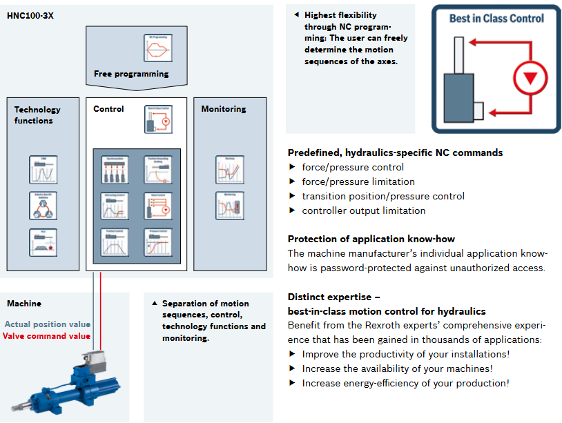
IndraDrive CSB01/CSH01/CDB01 is a modular servo drive control unit launched by Bosch Rexroth. As the control core of the IndraDrive drive system, it is divided into two series: BASIC (basic type) and ADVANCED (advanced type), suitable for single axis or dual axis drive scenarios. The product focuses on modular expansion, multi protocol compatibility, and high-precision control, which can be seamlessly matched with Rexroth IndraDyn series motors and various encoders. It is widely used in industrial automation equipment such as machine tools, packaging, printing, and material handling, meeting the driving and control needs of single machine or multi axis collaboration.
Product series and core configuration
Series model classification, number of axes, configuration characteristics, core differences
BASIC CSB01.1N (FC/SE/PB/AN) single axis fixed configuration, no additional expansion slots, only supports preset communication protocols, non expandable optional modules
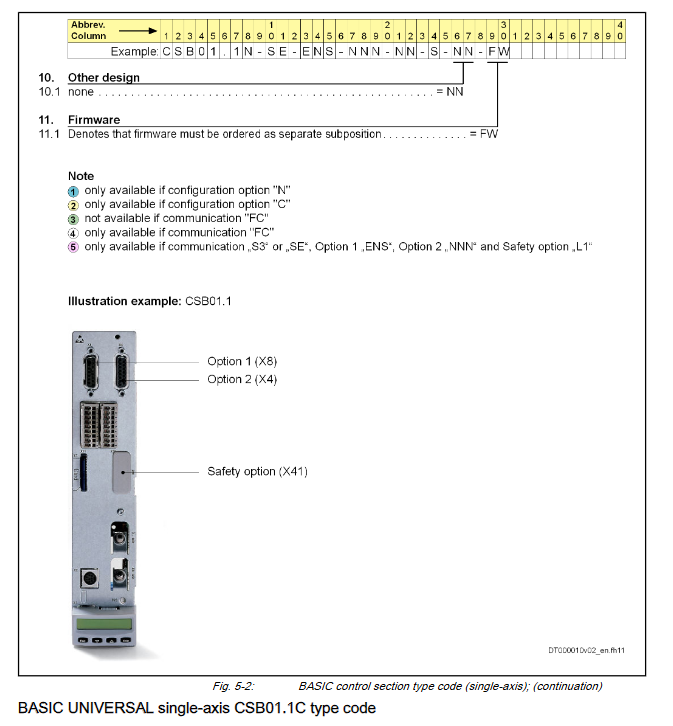
BASIC CSB01.1C single axis configurable, including expansion slots to support communication, encoder, and security module expansion
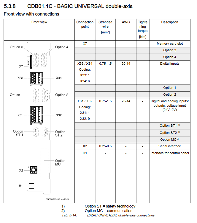
BASIC CDB01.1C dual axis configurable, dual axis independent control supports dual axis synchronization, multiple expansion slots
ADVANCED CSH01.1C/CSH01.2C/CSH01.3C Single axis Advanced Configurable, Multiple Expansion Slot Supports Cross Communication (CCD), Higher Control Frequency (62.5 μ s)
Core functions and technical parameters
control performance
Control cycle: current control 62.5-125 μ s, speed control 250-500 μ s, position control 500-1000 μ s.
Switching frequency: Supports 2kHz-16kHz, adjustable through parameter P-0-0001.
Compatible with encoders: Supports 12V (ENS module), 8V (EN1 module), 5V (EN2 module) power supply, compatible with various encoder types such as Sin cos, Hiperface, EnDat 2.1, etc.
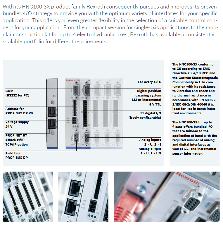
communication interface
Built in protocols: BASIC series supports fixed protocols such as Sercos, PROFIBUS, analog, etc; The ADVANCED series supports Multi Ethernet (EtherCAT/ProfiNet) and CANopen/DeviceNet.
Extension protocol: Supports Sercos III, Parallel interface, Cross Communication (CCD), etc. through optional modules.
Debugging interfaces: RS232 serial port (X2), Engineering Ethernet interface (X26), supporting control panel and MMC card parameter reading and writing.
I/O and scalability
Digital I/O: The basic unit includes 5-22 digital inputs and 0-4 digital outputs, supporting Type A/B/C/D inputs (24V, 3mA).
Analog I/O: The basic unit includes 2 analog inputs (± 10V/0-20mA) and 2 analog outputs (0-10V), which can be extended to 4-6 inputs and 4 outputs through AN/MA1 modules.
Expansion module: Supports encoder simulation (MEM), digital I/O expansion (MD1/MD2), SSI encoder evaluation (MD2 module integration).
safety technology
Basic security: L1 (start lock, compliant with EN60204-1 stop category 0) L2(Safe Torque Off,SIL3/PL e)。
Advanced security: S1 (Safe I/O), S2 (Safe Motion), supporting functions such as safe stop and safe speed limit, SIL2/PL d)。
Safe power supply: Independent 24V power supply (19.2-30V), maximum current 1.6A.
Environmental and power supply parameters
Power supply requirements: Control voltage DC 24V (fluctuation range 19-30V), basic unit power consumption 8-16W, optional module 1-6W.
Environmental conditions: working temperature 0-45 ℃, storage temperature -30-85 ℃, protection level IP20, anti electromagnetic interference (compliant with EN 61000 series standards).
Optional module details
Module type represents the model, core functions, and key parameters
Communication module SE (Sercos) fiber optic communication, supporting 16MBaud with fiber optic cable, maximum transmission distance of 100m
Communication module PB (PROFIBUS) bus communication, supports 12MBaud 9-pin D-Sub interface, shielded twisted pair cable
Encoder module ENS 12V encoder evaluation, compatible with Hiperface/EnDet 2.1 input frequency 400kHz, 12 bit A/D conversion
Encoder module EN1 8V rotary transformer/HSF encoder evaluation input frequency 18kHz, 12 bit A/D conversion
I/O expansion module MA1 2 analog inputs+2 analog outputs 12 bit resolution, ± 10V output
I/O expansion module MD2 16 channel digital I/O+SSI encoder evaluation digital I/O support 24V/0.5A, SSI clock frequency 100-1000kHz
The safety module S2 (Safe Motion) requires encoders for safety stop, speed limit, and position limit, and supports multiple safety function combinations
Installation and maintenance requirements
Installation specifications
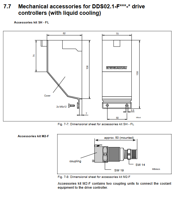
Installation method: 35mm standard guide rail (EN 60715), vertically installed, with at least 2cm of reserved heat dissipation space above and below.
Wiring requirements: Digital I/O requires external 24V power supply. It is recommended to connect protective diodes in series to prevent polarity reversal; The signal cable and power cable are wired separately, and the shielding layer is grounded at both ends.
Insertion and removal restrictions: The control unit and power unit should not be inserted or removed more than 20 times to avoid poor contact.
Maintenance points
Firmware update: Update firmware through MMC card (PFM02.1) or Engineering interface, supporting parameter backup and recovery.
Fault diagnosis: Read fault codes through LED indicator lights, control panel or upper computer, and support 16 channel real-time data recording.
Spare parts requirements: Only Bosch Rexroth certified spare parts are allowed, and parameters need to be reconfigured after module replacement.
Typical Applications
Single machine drive: machine tool spindle/feed axis, packaging machinery actuator, printing machine tension control.
Multi axis collaboration: Material handling robots, assembly line multi axis synchronization, automated production line drive system.