REXRTOH IndraControl VDP 16.3, VDP 40.3, VDP 60.3 Operator Display
The official operation manual for Bosch Rexroth IndraControl VDP 16.3/VDP 40.3/VDP 60.3 series operator displays (March 2014 version) revolves around safety specifications, product parameters, assembly wiring, debugging and maintenance, and service support. It specifies that the three models are equipped with 12 inch (800 × 600 pixels), 15 inch (1024 × 768 pixels), and 19 inch (1280 × 1024 pixels) TFT displays, with a protection level of IP65 (front panel)/IP20 (rear panel), supporting touch/button operations and CDI/USB/XSER/XVID interfaces. It provides detailed specifications for 24V power supply connection, cable selection (such as CDI cable with a maximum length of 50 meters), installation spacing (≥ 50mm around the perimeter), and troubleshooting process. The product complies with UL/CSA/CE certification and provides full process operation guidance for professionals in industrial scenarios such as machine tools and packaging machinery.
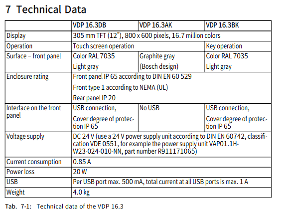
Core technical parameters
Parameter category VDP 16.3 VDP 40.3 VDP 60.3 Remarks
Display screen specifications include 12 inch TFT, 800 × 600 pixel 15 inch TFT, 1024 × 768 pixel 19 inch TFT, and 1280 × 1024 pixel, all of which support 16.7 million colors
Operation mode: Touch/Button (some models) Touch/Button/Touch+Button Touch Operation button models include 16 M keys (L1-L8/R1-R8)
Protection level: front panel IP65, rear panel IP20, front panel IP65, rear panel IP20, front panel IP65, rear panel IP20 in accordance with DIN EN 60529
Power supply requirement: DC 24V, current consumption: 0.85A DC 24V, current consumption: 1.05A DC 24V, current consumption: 1.7A. The power supply must comply with DIN EN 60742 standard
Power loss 20W, 25W, 40W-
USB interface front panel 1 (some models)+back panel 4 front panel 1 (some models)+back panel 4 front panel 1+back panel 4 single port maximum 500mA, total current ≤ 1A
Equipment weight 4.0kg 5.8kg 7.3kg-
External dimensions (width × height) 350 × 290mm (standard)/360 × 300mm (customized) 407 × 370mm (standard)/417 × 380mm (customized) 483 × 400mm Installation depth of 41mm
Key points of safety regulations
(1) Electrical safety
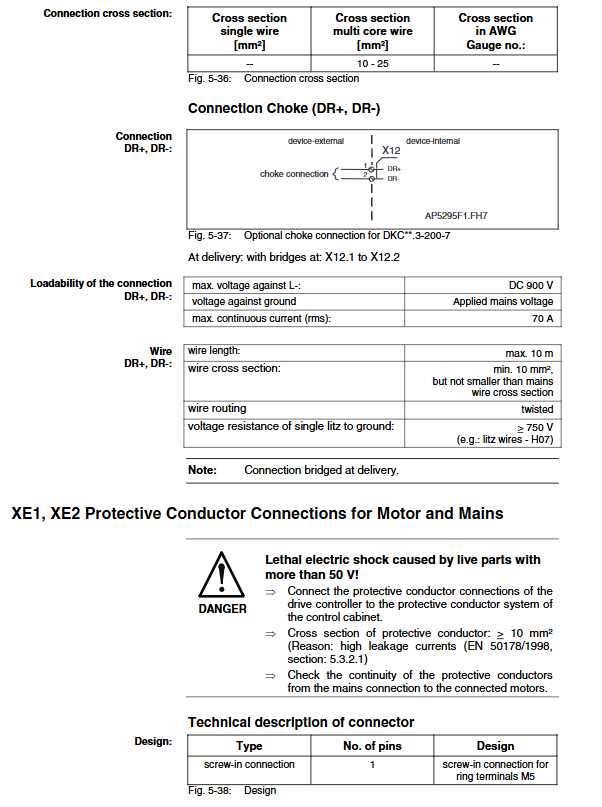
The power supply must comply with overvoltage category II, and the 230V/400V wiring must strictly distinguish between phase lines, neutral lines, and protective grounding (PE). The cross-sectional area of the protective grounding wire should be ≥ 6mm ² (green/yellow).
It is prohibited to connect power units suitable for low voltage (such as 24V) to non design supply voltage to avoid the risk of electric shock.
Functional grounding (FE) must be connected, otherwise the potential difference between VDP and PC may damage electronic components when the voltage is interrupted and restored.
(2) Operational safety
The touch screen is only allowed to be operated with fingers or a dedicated touch pen (part number 1070923266), and sharp objects are prohibited to avoid damaging the screen or front panel.
Do not use solvents (such as diluents) and high-pressure cleaning equipment during cleaning to prevent damage to the film surface and seals.
The equipment needs to be installed vertically with a maximum deviation of ± 45 °. A space of ≥ 50mm should be reserved around it for heat dissipation and cable layout to avoid blocking the LED indicator lights on the connectors.
(3) Compliance requirements
The product complies with the EMC Directive 2004/108/EC and follows EN 61000-6-4 (emission standard) and EN 61000-6-2 (immunity standard).
It has been certified by UL508 (Industrial Control Equipment) and CSA C22.2 No.142-M1987, with UL document number E210730. The certification is only valid in the delivery state and needs to be revalidated after modification.
Assembly and connection specifications
(1) Installation requirements
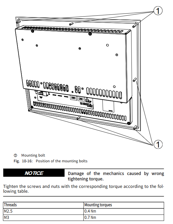
Installation Cut Size (Table): | Model | Installation Cut Width × Height (mm) | Installation Bolt Hole Diameter (mm) | Bolt Quantity | | —- | —- | —- | | | | | VDP 16.3 | 335 × 275 | 5 | 8 | | | VDP 40.3 | 392 × 355 | 5 | 8 | | VDP 60.3 | 463 × 370 | 5 | 8|
Tightening torque: 0.4Nm for M2.5 bolts, 0.7Nm for M3 bolts, 1.4Nm for M4 bolts, and 2.8Nm for M5 bolts to avoid damaging mechanical structures due to improper torque.
Cable layout: CDI cables should be kept away from interference sources such as motor cables, with a bending radius of ≥ 4 times the cable diameter (during installation) and ≥ 8 times the cable diameter (during permanent movement), to avoid mechanical stress (tension, torsion, etc.).
(2) Wiring specifications
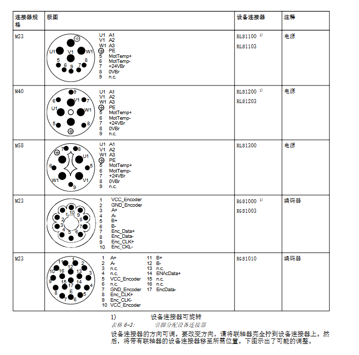
Power supply connection: Connect a 24V power supply through the X1S1 interface, with pin 1 being+24V, pin 2 being 0V, and pin 3 being empty. Copper wires are required, and it is recommended to use VAP01.1H-W23-024-010-NN power supply unit (part number R911171065).
Control cabinet PC connection: Connected through CDI interface (XSER purple/RJ45 data interface, XVID black/RJ45 image interface), requires the use of 2 dedicated CDI cables, with a maximum distance of VDP 16.3 (80 meters), VDP 40.3 (70 meters), VDP 60.3 (60 meters), exceeding which Y-Repeater (VAC01.1S-YD1-NNN, part number R911171187) is required.
USB connection: USB 2.0 cable up to 5 meters long, high anti-interference USB cable (such as RKB0050/001.0, part number R911172944) is required for noisy environments. XUSBIN interface (Type B) is used to connect to the control cabinet PC, up to 5 meters long.
(3) DIP switch settings
S1/2 switch: OFF (CDI cable length ≤ 30 meters), ON (CDI cable length>30 meters), S1/1 has no function.
USB speed: When the cable is ≤ 5 meters and S1/2=OFF, it supports 480Mb/s (additional USB cable is required); When the cable is greater than 5 meters, the speed is 12Mb/s and USB hubs are not supported.
Debugging and maintenance
(1) Debugging
The product does not require configuration and can be used directly. When starting, the VDP power supply needs to be turned on first or turned on simultaneously with the control cabinet PC to ensure normal screen display.
Resolution setting: The corresponding resolution (VDP 16.3:800 × 600) needs to be set in the graphics card driver of the control cabinet PC; VDP 40.3:1024×768; VDP 60.3:1280 × 1024), after setting, restart the PC to take effect.
(2) Maintenance points
Regular maintenance: Check the tightness of the plug and terminal connection and whether the cable is damaged at least once a year. Damaged parts should be replaced immediately.
Backlight management: The backlight life is about 50000 hours (in a 25 ℃ environment), and the backlight off time can be set through the “Power Options” in the Windows Control Panel to extend its service life.
Cleaning requirements: Use a dry soft cloth for cleaning, avoid solvents and high-pressure water flow, and avoid seal failure that may cause a decrease in protection level.
(3) Troubleshooting (Table)
Possible causes and solutions for the fault phenomenon
No image display power supply not connected, CDI cable reversed, resolution setting error check X1S1 power supply, reconnect CDI cables (XSER-XSER, XVID-XVID), set correct resolution and restart PC
USB devices cannot be used due to excessively long cables, improper DIP switch settings, replacement of ≤ 5-meter USB cables, and setting S1/2 switches based on CDI cable length
Touch screen unresponsive and uncalibrated, driver issues recalibrate touch screen, confirm pre installed English keyboard driver unchanged
Screen resolution error. Improper graphics card driver settings. Select the corresponding model resolution in the graphics card driver and restart the PC
Environmental disposal
The product can be returned to Bosch Rexroth AG for free disposal, provided that there is no oil, grease, or other contaminants. The return address is Bosch Rexroth AG, Electric Drives and Controls, B ü rgermeister Dr. Nebel Stra ß e 2, 97816 Lohr am Main, Germany.
Packaging materials (cardboard, plastic, wood, polystyrene) are recyclable and do not need to be returned; The product contains electronic components and metals, which need to be classified and recycled to avoid environmental pollution.