Call us 24/7uaedcs@163.com
Welcome to the official website of CNIACS Automation Technology Co., Ltd!
Call us 24/7uaedcs@163.com

Woodward easYgen LS-6XT Multi-Breaker control

Basic Information

Product model easyYgen LS-6XT series (circuit breaker controller)

High end circuit breaker control with core positioning for complex power management scenarios, integrating synchronization, protection, and communication functions

Target users: OEM switchgear manufacturers, generator set installers, and system integrators

Adapt to scenarios such as parallel operation of power grids, islanding operation, multi unit linkage, peak shaving, and import/export power control

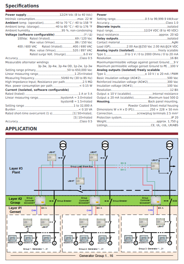
Core hardware configuration and specifications

(1) Power supply and environmental parameters

Category specific specifications

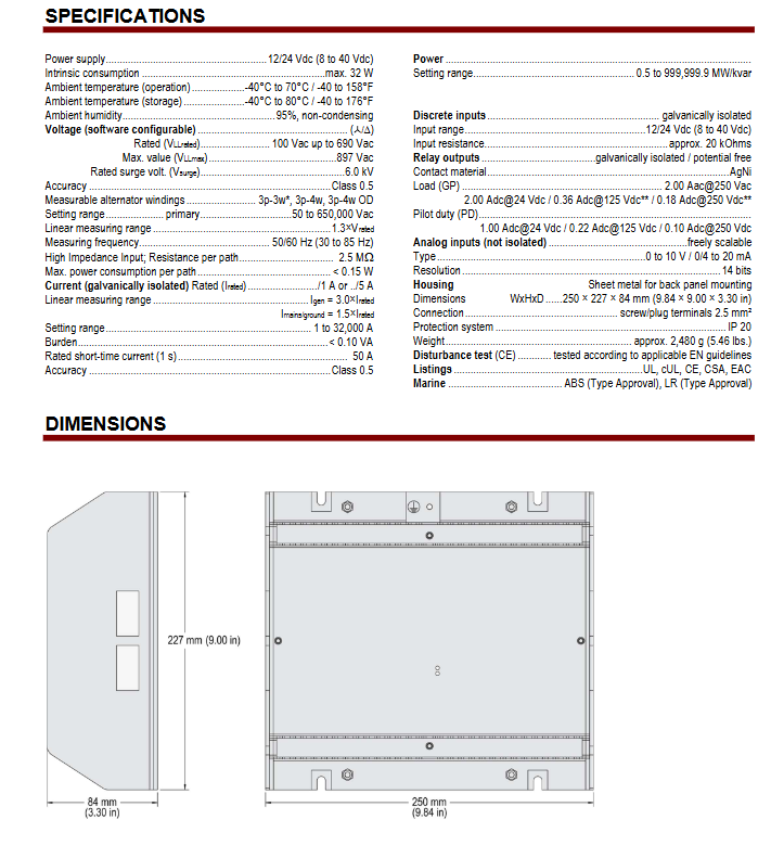
Power input voltage range 8-40Vdc (supports 12/24VDC), maximum power consumption 22W

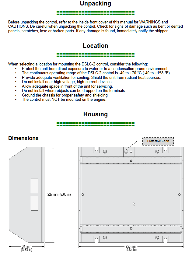
Working environment temperature -40 ° C~70 ° C, humidity 95%, no condensation

Storage environment temperature -40 ° C~80 ° C

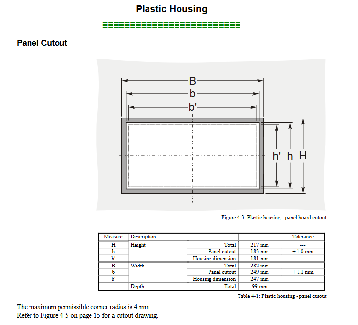
Structural specifications: Metal powder coated shell, size 250 (W) × 228 (H) × 50 (D) mm (P1 model), weight approximately 1.75kg, protection level IP20

Certification compliance CE, UL, cUL, LR (Lloyd’s Register), ABS (American Bureau of Shipping) certification

(2) Measurement and I/O interface

Interface type specification details

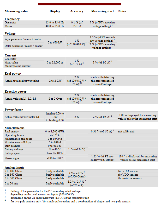
Voltage measurement supports independent measurement of system A, system B, and auxiliary voltage; Suitable for 100/400/600/690Vac; Measurement accuracy Class 0.5; Support 3Ph3W/3Ph4W/1Ph2W/1Ph3W wiring

Current measurement support system A and system B for current measurement; CT input 1A/5A software optional; The linear measurement range of System A is 3.0 × Irated, and System B is 1.5 × Irated; Measurement accuracy Class 0.5

Discrete Input (DI) 12 channel optically isolated input, voltage range 8-40Vdc, input resistance of approximately 20k Ω; supports IKD module expansion to 32 channels

Discrete Output (DO) 12 relay outputs, contact material AgNi, load 2A@250Vac /24Vdc; Support IKD module expansion to 32 channels

Analog input (AI) with 3 isolated inputs, supporting 0-1V/0-2000 Ω/0-20mA, with a resolution of 16 bits; Freely calibratable

Analog output (AO) with 2 isolated outputs, supporting ± 10V/± 20mA/PWM, with a resolution of 12 bits; AO # 1 insulation voltage 100Vac, AO # 2 reinforced insulation 300Vac

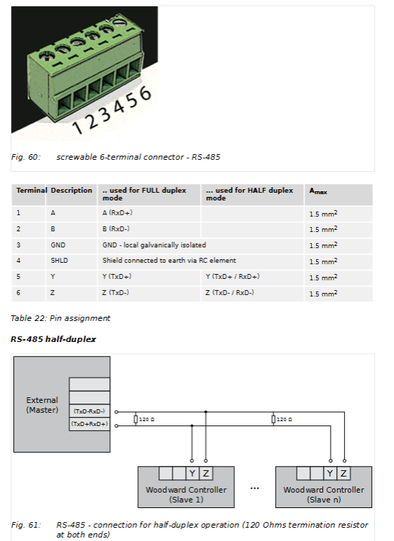
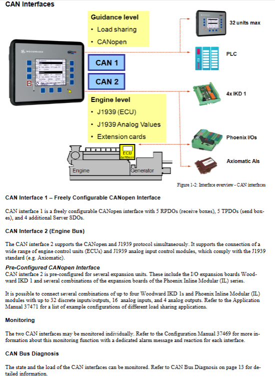
(3) Communication interface

Core parameters of communication type

Redundant communication supports CAN ETH and Eth ETH redundancy schemes to avoid single point failures

Ethernet 3 independent RJ-45 ports, supporting 10/100Base-T, used for remote control, visualization, and group controller linkage

RS-485 supports Modbus RTU protocol for remote control and data exchange

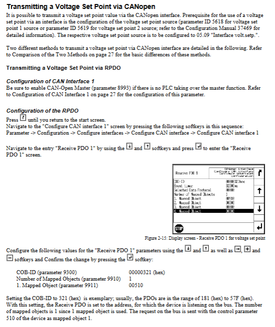
CAN bus supports CANopen protocol for IKD module expansion I/O and device interconnection

USB for ToolKit software configuration and maintenance

Core functions and features

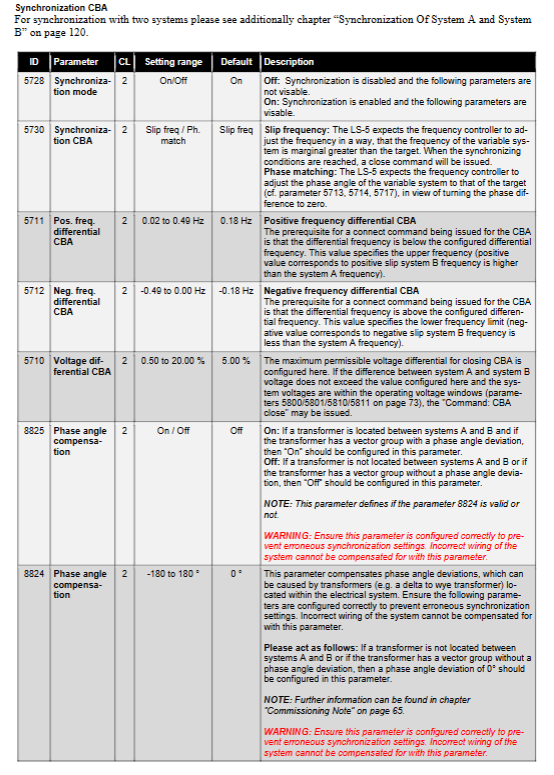
(1) Control and synchronization function

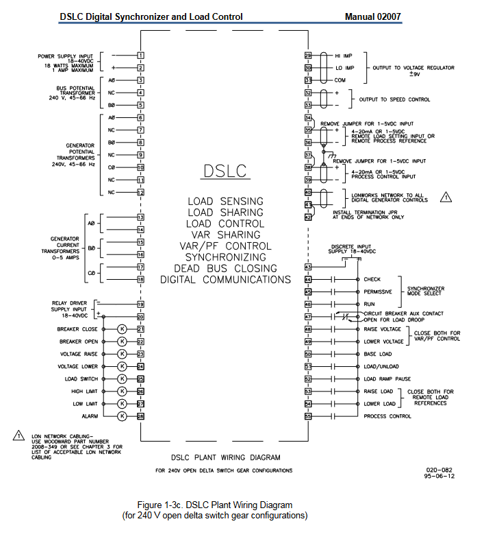
Circuit breaker control: Supports 1-2 circuit breakers (CBA/BBB), configurable closing/opening logic, supports pulse (<100ms) or continuous output

Load transfer mode: 4 options (Open Transition/Lost Transition/Interchange/Define Parallel), suitable for different power switching scenarios

Synchronous grid connection: supports phase matching, slip frequency synchronization, and has voltage matching function; Support forward/reverse synchronization between the power grid and the unit group

Dead bus closure: automatically detects no voltage bus, safely closes circuit breaker after meeting conditions, supports multi device negotiation mechanism

(2) Measurement and protection functions

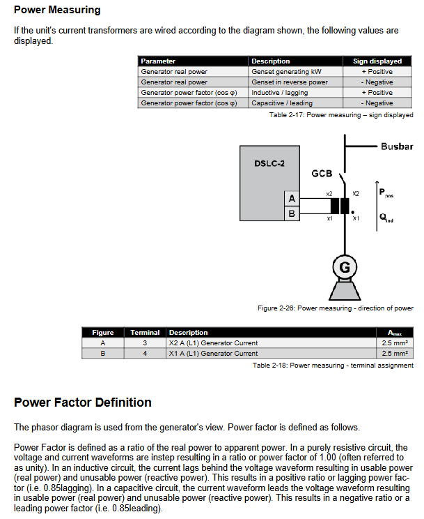
Power measurement: Class 1 accuracy, supports active/reactive power calculation, can access external sensor data

Built in protection: including ROCOF (rate of change), phase offset, flexible limit protection, etc., customizable protection logic

Monitoring range: key parameters such as voltage, current, frequency (30-85Hz), phase, power factor, etc

(3) Programming and Extension Features

LogicsManager: supports custom logic programming, associating I/O signals, alarm conditions, and control instructions

AnalogManager: Analog processing, supporting sensor curve calibration and custom conversion formulas

I/O Expansion: Connected to IKD module via CAN bus, expandable up to 32 DI/32 DO channels

Custom configuration: supports personalized configuration of HMI screen (RP-3000XT), alarm information, and logic rules

(4) System linkage and management

Scale support: up to 32 LS-6XT and 32 easyYgen-3400XT/3500XT linked; Or 64 LS-6XT units and 16 GC-3400XT units (with a maximum of 31 units per group) are linked together

Segmented control: supports load sharing management for 128 bus segments

Data synchronization: LS-6XT automatically synchronizes date and time with associated devices

Diagnostic function: Detailed communication diagnosis, visual monitoring of the status of all networked devices for easy troubleshooting

Woodward easyYgen LS-6XT series circuit breaker control unit

Basic Information

Product model easyYgen LS-6XT series (representative model LS-612XT-P1/P2)

Core positioning circuit breaker control, dual system synchronous monitoring, fault alarm, logic expansion

Adaptation target engine generator set (GCB/MCB/GGB control)

Certification qualifications UL/cUL, CE, Lloyd’s (ENV1/ENV2), ABS classification certification

System hardware and interface configuration

(1) Core interface parameters

Interface type specification details

The input voltage range of the power supply is 8-40Vdc. It is recommended to connect a 6A slow melting fuse in series, with a power consumption of about 6W

Voltage measurement (dual system) supports 3Ph4W/3Ph3W/1Ph3W/1Ph2W wiring; Measurement range 120/480/690Vac (PT secondary side)

Current measurement (dual system) supports L1/L2/L3 three-phase or single phase to ground measurement; CT input 1A/5A optional, system A occupies 6 terminals, system B occupies 2 terminals

Discrete Input (DI) 12 channel optical isolation, input voltage 8-40Vdc, supports NO/NC configuration; Can be extended to 32 channels (P2 model) through IKD module

Discrete Output (DO) 12 way relay, passive contacts, universal load 2A@250Vac /24Vdc; Can be extended to 32 channels (P2 model) through IKD module

Analog input (AI) 3 channels, supporting 0-2000 Ω (resistance type), 0/4-20mA (current type), 0-1V (voltage type), supporting Pt100/Pt1000/VDO sensors

Analog output (AO) 2 channels, supporting ± 20mA, ± 10V, PWM output, galvanic isolation, configurable filtering time constant

Communication interface RS-485: supports half/full duplex, with maximum transmission distance dependent on baud rate; USB 2.0: Service port, ToolKit connection; CAN Bus: Supports CANopen, up to 2500m (20kBaud); Ethernet: 3 RJ-45 ports, supporting 10/100Base-T, maximum transmission of 100m

(2) Structure and environmental specifications

Category specific parameters

The shell structure is made of metal material, with dimensions of 227 (width) x 250 (height) x 50 (depth) mm; the panel openings must comply with the drill plan

Protection level IP66 (screw installation), IP54 (fixture installation), IP20 (back)

Environmental tolerance working temperature -20 ° C~70 ° C, storage temperature -30 ° C~80 ° C; humidity 95%, no condensation (85% when ≤ 40 ° C)

Anti interference performance vibration: 5-100Hz sine sweep frequency (4G), 10-500Hz random vibration (1.04Grms); Shock: 40G sawtooth wave pulse (11ms)

Core functions and operations

(1) Core control function

Circuit breaker control: supports the closing/opening of CBA (main circuit breaker) and CBB (backup circuit breaker), can be configured with pulse (0.1-9.9s) or continuous output mode, supports automatic unlocking (Pre open pulse) function

Synchronous grid connection control: Monitor the voltage difference (0.50-20.00%), frequency difference (± 0.49Hz), and phase difference (± 60 °) of the dual systems, trigger grid connection after meeting the conditions, and support phase compensation (-180 °~180 °)

Dead bus closure: supports both A/B dual systems to be dead, one dead and one active scenario closure, detection threshold 0-30% rated voltage, delay 0-20s, supports multi device negotiation mechanism

Load transfer: Supports four modes: Open Transition, Closed Transition, Interchange, and Parallel

Fault decoupling: Monitor thresholds such as over/under frequency, over/under voltage, phase offset, df/dt, etc., and automatically disconnect the designated circuit breaker (CBA/BBB or both) upon triggering

(2) Programming and configuration methods

Configuration Method Operation Path Core Function

Local operation front-end panel (LCD+buttons) parameter viewing, mode switching, manual control of circuit breakers, alarm confirmation

Remote Panel RP-3000XT (Ethernet) fully functional visual operation, supporting Full/Annunciator/Off modes

PC configuration ToolKit software (Windows 7/8.1/10) includes full parameter configuration, logic programming, analog processing, data trend monitoring, and log export

LogicsManager supports logical combinations such as AND/OR/NAND, and can customize discrete I/O associations and alarm triggering conditions

Analog Manager supports 8 types of sensor curves, 2 custom tables (9-point calibration), and unit conversion (° C → ° F, bar → psi) for analog processing

(3) Alarm and Log

Alarm level: Level 6 (A-F), Level A/B for warning (no trip), Level C-F for shutdown (disconnect circuit breaker)

Event log: records 300 system events (including timestamps), supports FIFO storage, and can be manually cleared

Alarm monitoring: covering 20+types of alarms such as voltage/frequency exceeding limits, phase rotation mismatch, I/O faults, communication abnormalities, etc

Key configuration parameters

(1) Permission and password grading

Permission level, access method, core permissions

CL0 (user level) no password, only view data, confirm alarms

CL1 (basic level) password 0001 modification of non critical parameters (such as language, unit)

CL3 (debugging level) password 0003 full parameter configuration, logic programming, factory reset

CL5 (Super Debugging Level) Password 0500 Firmware Update, Advanced Parameter Configuration

Temporary permission algorithm generates password for temporary access to corresponding level, automatically exits upon timeout

(2) Example of Core Function Configuration Parameters

Parameter Category Key Parameters Default Value Configuration Range

Synchronous Control Voltage Difference Threshold (CBA) 5.00% 0.50-20.00%

Frequency difference threshold (CBA) ± 0.18Hz -0.49-0.49Hz

Phase difference threshold (CBA) ± 7.0 ° -60.0-60.0 °

Dead bus control detection threshold 10% 0-30%

Closing delay 5.0s 0.0-20.0s

Communication configuration CANopen baud rate 125kBaud 20-1000kBaud

Ethernet IP Mode Static/Dynamic (DHCP)

Load Transfer Time (CBA) ↔ CBB) 1.00s 0.50-99.99s

Key issue

Question 1: How is the dual circuit breaker (CBA/BBB) control function of LS-6XT implemented, and what are the core configuration differences?

Answer: The dual circuit breaker control is achieved through the “CBA/BBB mode”, and the core is the independent control and linkage logic of the two circuit breakers: ① Hardware configuration: CBA corresponds to the main circuit breaker, CBB corresponds to the backup/load circuit breaker, both support closing/opening pulse/continuous control, and can be configured with automatic unlocking (Pre open) function; ② Core differences: CBA focuses on main circuit grid connection, dead bus closure, and system A decoupling, while CBB focuses on backup circuit switching and system B associated control, with CBA having higher closure priority than CBB; ③ Linkage logic: supports load transfer (four modes), synchronous grid connection linkage (CBB synchronization after CBA closure), and selective disconnection in case of failure (such as CBA disconnection in case of system A failure and CBB disconnection in case of system B failure); ④ Configuration points: It is necessary to switch between “CBA”/”CBA/BBB” modes through parameter 9018 (Breaker mode), and configure the synchronization threshold, dead bus condition, and linkage delay of both modes separately.

Question 2: How to configure and use the extended I/O (IKD module) of LS-6XT, and what extension scenarios are supported?

Answer: The IKD module is an external I/O expansion solution, with the following core configurations and scenarios: ① Supported module types: IKD1 (8DI+8DO), IKD-IN-16 (16DI), IKD-OUT-16 (16DO), P1 model supports 2 IKDs (16DI+16DO), P2 model supports 4 IKDs (32DI+32DO); ② Connection method: Connected through CAN1 bus, CAN baud rate and module address need to be configured, shielded cable exposed length ≤ 25mm; ③ Configuration path: “Configure Input/Output → External Discrete Input/Output” in ToolKit, can set DI alarm level, delay time, and logical association of DO; ④ Extended scenarios: Suitable for complex systems that require more discrete signal acquisition (such as multi-sensor alarms) or output control (such as multi actuator linkage), such as multi loop state monitoring in ship power systems and multi device linkage control in industrial units.

Question 3: What is the core logic and safety mechanism of the synchronous grid connection and dead bus closure function of LS-6XT?

Answer: Both are the core functions of circuit breaker closure, and the logic and safety mechanism are as follows: ① Synchronous grid connection logic: Real time monitoring of dual system voltage/frequency/phase, meeting preset thresholds (voltage difference ≤ 20%, frequency difference ≤± 0.49Hz, phase difference ≤± 60 °) and continuously setting time (default 3s), triggering closure; Supports two synchronization modes: “slip frequency” and “phase matching”, which can offset transformer phase offset through phase compensation; ② Dead bus closure logic: detects that the system voltage is below the threshold (0-30% rated voltage) and has a continuous delay time (0-20s), triggering after meeting the “no other device closure request” (multi device negotiation), supporting three scenarios: A dead B dead, A dead B live, A live B dead; ③ Security mechanism: Verify phase sequence consistency (CW/CCW) before synchronous grid connection, and block closure if inconsistent; The closure of the dead bus requires the “Enable close” logic to be enabled through LogicsManager, and there should be no C/F level alarms; In multi device scenarios, using “device number priority” to avoid simultaneous closure and automatically releasing permissions after closure failure ensures system security.

WOODWARD LS-5 Series | LS-521 V2 Circuit Breaker Control

Basic Information

Product Model LS-521 V2 (Option K12)

Core positioning: Circuit breaker closing/opening control, dual system synchronous monitoring, fault alarm and log recording

Suitable for generator circuit breaker (GCB) and grid circuit breaker (MCB) control

Certification qualifications UL/cUL (ordinary area), CE, Lloyd’s (ENV1/ENV2), ABS classification certification

System hardware and interface configuration

(1) Core interface parameters

Interface type specification details

The input voltage range of the power supply is 8-40Vdc, with a power consumption of about 6W; it is recommended to series connect a 6A slow melting fuse

Voltage measurement (dual system) supports 3Ph4W/3Ph3W/1Ph3W/1Ph2W wiring; Measurement range: 120Vac (0-150Vac), 480Vac (0-600Vac)

Current measurement (System A) supports L1/L2/L3 three-phase or single phase to ground measurement; CT input 1A/5A optional

Discrete Input (DI) with 8 channels and optical isolation design; Supports NO/NC configuration, input voltage 8-40Vdc, input resistance approximately 20k Ω

Relay output (DO) 6 channels, passive contacts; Universal load 2A@250Vac / 2A@24Vdc , Piloted load 1A@24Vdc

Communication interface CANopen: default 125kBaud, maximum transmission distance 2500m (20kBaud); RS-232: default 19.2kBd, supports ToolKit configuration

(2) Structure and environmental specifications

Category specific parameters

Shell structure made of plastic material, dimensions 219 (width) × 171 (height) × 61 (depth) mm; panel opening 186 × 138mm

Protection level IP66 (screw installation), IP54 (fixture installation), IP20 (back)

Weight approximately 850g

Working environment temperature -20 ° C~70 ° C, storage temperature -30 ° C~80 ° C; humidity 95%, no condensation (85% when ≤ 40 ° C)

Anti interference performance vibration: 5-100Hz sine sweep frequency (4G), 10-500Hz random vibration (1.04Grms); Shock: 40G sawtooth wave pulse (11ms)

Core functions and operations

(1) Core control function

Circuit breaker control: supports the closing/opening control of one circuit breaker (CBA), and can be configured with one or two relay drivers; Closed pulse width 0.1-0.5s, open pulse width 0.1-9.9s

Synchronous grid connection control: Monitor the voltage difference (maximum 20% rated voltage), frequency difference (± 0.49Hz), and phase difference (maximum 20 °) between system A and system B. When the conditions are met, trigger grid connection and support transformer phase compensation (-180 °~180 °)

Dead bus closure: supports closure control for both A/B dual systems in dead and one dead/active scenarios; Dead bus detection threshold 0-30% rated voltage, delay time 0-20s

Phase sequence monitoring: Support system A/B phase sequence detection (CW/CCW), block circuit breaker closure and alarm when phase sequence mismatch occurs

(2) Configuration and operation mode

Configuration Method Operation Path Core Function

Front panel buttons+LCD display screen parameter viewing, mode switching (automatic/manual), circuit breaker manual control, alarm confirmation

ToolKit software PC installation (supports Windows 7/8.1/10) full parameter configuration, logic programming (LogicsManager), data trend monitoring, event log export

(3) Alarm and Log

Alarm level: Level 6 alarm (A-F), Level A/B warning (no trip), Level C-F shutdown (immediately disconnect the circuit breaker)

Event log: 300 FIFO storage records alarm triggering/recovery, operation status changes (such as automatic/manual switching, circuit breaker action), supports manual clearing

Key configuration parameters

(1) Password and permission grading

Default password for permission level, core permissions

CL0 (user level) does not only view data, set language/time

CL1 (Service Level) 0001 modifies non critical parameters (such as units, alarm reset time)

CL3 (debugging level) 0003 full parameter configuration, factory reset, logic programming

(2) Example of Core Configuration Parameters

Parameter Category Key Parameters Default Value Configuration Range

Synchronous control voltage difference threshold 5.00% 0.50-20.00%

Frequency difference threshold (positive/negative) ± 0.18Hz -0.49-0.49Hz

Phase difference threshold 20 ° 0-20 °

Dead Bus Control Dead Bus Detection Threshold 10% 0-30%

Dead bus closure delay 5.0s 0.0-20.0s

Communication configuration CANopen baud rate 125kBaud 20-1000kBaud

RS-232 baud rate 19.2kBd 2.4-115kBd

Woodward MicroNet TMR ® 5009 Digital Control System

Basic Information

Product series MicroNet TMR ®  five thousand and nine

Core positioning: High reliability prime mover control (focusing on fault tolerance and safety control)

Suitable for gas turbines, steam turbines, generators, and various types of prime movers

Certification qualifications UL/cUL (Class I Division 2), CE (EMC/LVD), Lloyd’s (ENV1/ENV2)

System hardware configuration

(1) Chassis specifications

Chassis Type: Main Control Chassis, Power Chassis

The core function supports the control module and I/O module to provide redundant power output

Module capacity: 3 core areas (each area contains 6 slots), 2 main power module slots

Size Weight 22kg (48lb) Weight 8kg (17lb)

Cooling method: Top forced air cooling fan (1 per 6 slots) with dual cooling fans on top and bottom

(2) Core module parameters

Module type key specifications

CPU module processor: Motorola 68040; Memory: Built in RAM/Flash; Redundancy quantity: 3; Real time clock: NiCd battery (non user replaceable, 16 hours of charging, 3 months of battery life)

Main power module input specifications: 18-36Vdc/88-132Vac/180-264Vac, etc; Output: 24Vdc x 6 channels (6A per channel); Redundancy features: load sharing, hot swapping

Core power module input: 24Vdc; Output: 5VDC (10A)+5V pre charge; Function: Power supply for single core area modules

Analog I/O module speed input: 4 channels (MPU/proximity probe, 0.5-25kHz); Analog input: 8 channels (4-20mA, accuracy 0.1%); Analog output: 4 channels (4-20mA, load 600 Ω); Output of actuator: 2 channels (4-20mA/20-160mA, software optional)

Discrete I/O module discrete input: 24 channels (optically isolated, 18-32Vdc/100-150Vdc, input current) 13mA@24V ); Discrete output: 12 channels (relay, Form-C contact, 3A resistive load)

SIO communication module serial port quantity: 4; Supporting protocols: RS-232 (1/2 port), RS-232/422/485 (3/4 port); Transmission distance: RS-232 (15m), RS-485 (1219m)

(3) Terminal module configuration

Number of terminal module types and core functions

ATM (Analog Terminal Module) 2 analog signal/speed signal wiring conversion; Built in 100mA fuse; Support MPU/proximity probe wiring

DTM (Discrete Terminal Module) 4 discrete signal/relay output wiring conversion; Support internal/external 24V power supply; Integrated potential fault detection circuit

Core functions and features

(1) Control function

Speed control: Supports input from MPU (100-25000Hz) and proximity probe (0.5-25000Hz), with an accuracy of 0.03%

Analog control: 8 channels of 4-20mA analog inputs (supporting two-wire/three wire sensors), 4 channels of 4-20mA analog outputs (accuracy 0.2%)

Actuator driver: 2-channel PWM output (4.88kHz), supports single coil/double coil actuators, configurable jitter current (25Hz)

Discrete control: 24 discrete inputs (including 4 preset functions: emergency stop/reset/speed up/down), 12 relay outputs (including 2 dedicated outputs: stop/alarm)

(2) Redundancy and Fault Protection

The third mock examination Redundancy (TMR): three CPU modules work in parallel, two out of three signals vote, and single module failure does not affect system operation

Potential Fault Detection (LFD): Relay outputs are configured in series parallel with 6 relays, periodically detecting contact status to avoid potential fault accumulation

Fault safety state: When the I/O Lock function is triggered, the discrete output loses power and the analog output returns to zero, ensuring equipment safety

Redundant power supply: load sharing of two main power modules, seamless takeover of the other module in case of single power failure

(3) Communication and Compatibility

Communication protocol: Supports Modbus ASCII/RTU, DDE (PCI engineering station docking)

Interface types: CPU with built-in RS-232 ports (3), SIO module serial ports (up to 8)

Compatible products: DSLC synchronous load controller, RPS active power sensor (4-20mA power signal input), OCP operation panel

Installation and environmental specifications

(1) Environmental parameters

Category specifications

Working temperature: 0 ° C~55 ° C (without external heat source)

Storage temperature -20 ° C~70 ° C

Relative humidity 5%~85% (no condensation)

Vibration protection Lloyd’s ENV2: 13-150Hz @ 1.0G (10 frequency sweeps)

Impact protection US MIL-STD-810C: 15g 11ms half sine pulse

(2) Power supply and wiring specifications

Power type, input range, fuse specifications, wire specifications

Low voltage DC 18-36Vdc 40A slow melting 10mm ² (8AWG)

Medium voltage AC/DC 88-132Vac/100-150Vdc 20A slow melting 4.0mm ² (12AWG)

High voltage AC/DC 180-264Vac/200-300Vdc 10A slow melting 2.5mm ² (14AWG)

(3) Maintenance cycle

Maintain project cycle

Cooling fan replacement for main/power chassis fan: 50000 hours; Cabinet fan: 60000 hours

Air filter cleaning for 60 days to 18 months (depending on environmental dust concentration)

Regular CPU battery inspection (no fixed cycle, replacement in case of leakage/damage)

Woodward MicroNet ™  Simplex/Plus digital controller

Basic Information

Product series MicroNet Simplex (single CPU), MicroNet Plus (dual CPU redundancy)

Core positioning: full lifecycle control of the prime mover (start-up, operation, monitoring, shutdown)

Suitable for gas turbines, steam turbines, diesel engines, gas engines, and water turbines

Certification qualifications UL/cUL, CE, CSA, EAC, ABS (Classification), LR (Classification) ATEX Zone 2

System hardware configuration

(1) Chassis specifications

Specification: 14 slot chassis, 8 slot chassis

Slot distribution: 2 power slots+2 CPU slots+10 I/O slots, 2 power slots+2 CPU slots+4 I/O slots

Size (W × H × D) 356 × 340 × 178mm, suitable for small installation scenarios

Redundant intelligent fans for heat dissipation (6/14 slots, 4/8 slots), redundant intelligent fans for 65 ° C over temperature alarm (4), 65 ° C over temperature alarm

Grounding of chassis PE, installation of screw grounding (M4/# 8-32) is the same as 14 slot chassis

(2) Core module parameters

① CPU module

Model P1020 PowerPC CP5-200 (Motorola)

Processor 800MHz dual core MPC5200

Storage 512MB RAM+768MB Flash 128MB DDR RAM+64MB Flash

Communication interfaces: 4 Ethernet (2 × 1000Mbps), 5 CAN, 1 USB, 2 Ethernet, 2 CAN, 1 RS-232/485

Working temperature: 0 ° C~55 ° C -40 ° C~85 ° C

Redundancy Support (Slot A1/A14) Support (Slot A1/A8)

② Power module

Input specifications 24Vdc (18-36Vdc) 110Vac/dc (88-132Vac/100-150Vdc) 220Vac (180-264Vac)

Output power 600W 1250VA (AC)/600W (DC) 1250VA

output voltage 24V@12A The 5V@32A 、 5V pre charge @ 3A same left same left

Redundancy feature dual module load sharing, supporting cold plugging with same left and same left

Protection function: Input overvoltage/undervoltage, over temperature, and output short circuit protection are the same as left and left

③ I/O module

Key parameters of module type

Discrete I/O (48/24 Combo) with 48 DI (optically isolated, 18-32Vdc) and 24 DO (relay output), update time 5ms

Discrete DI (48Ch) 48 channel optically isolated input, supporting internal/external 24V power supply, input current 3mA@24Vdc

Discrete DO (64Ch) 64 channel open drain output, compatible with 16Ch/32CH relay modules, maximum load 2A@250Vac

Speed sensor module with 4 inputs (optional MPU/Eddy/Prox), frequency range 1Hz~25kHz, accuracy 0.01%

Analog I/O (24/8) with 24 channels of AI (4-20mA/0-5V) and 8 channels of AO (4-20mA), with a resolution of 16 bits and an accuracy of 0.1%

④ Communication module

Module type functional parameters

Remote RTN supports rack expansion, copper cable 30m/fiber optic 2km, up to 8 racks interconnected

SIO module with 4 serial ports (2 x RS-232, 2 x RS-232/422/485), baud rate of 110Bd~57.6kBd

Core functions and features

(1) Control function

Core control: speed control, load distribution, sequence control, surge control, auxiliary system control

Monitoring and alarm: over temperature/over pressure/over speed monitoring, module fault alarm, trend recording

Redundancy guarantee: CPU redundancy (automatic fault switching), power redundancy (load sharing), I/O redundancy (dual sensors/dual modules)

(2) Communication and Expansion

Communication protocols: TCP/IP, Modbus RTU, Modbus TCP, CANopen, DeviceNet

Scalability: Supports 7 expansion racks, copper cable transmission for 30m, fiber optic transmission for 2km (multimode)

Remote access: Supports PLC/DCS access via Modbus TCP, supports USB/Ethernet local configuration

(3) Safety and Compliance

Safety features: IOLOCK fault safety (output power loss), requirement for independent overspeed protection device, ESD protection

Environmental compliance: ATEX Zone 2 (explosion-proof), Class I Division 2 (hazardous area)

Electromagnetic compatibility: Complies with EN 61000 and needs to be installed in a metal cabinet

Software and Configuration

Development environment: Woodward GAP (graphical programming) Ladder Logic, Support rate group scheduling (minimum 5ms)

Configuration tools: AppManager (firmware upgrade, network configuration, fault monitoring), ToolKit (visual debugging)

Diagnostic functions: module LED fault codes, real-time status monitoring, historical fault records, remote diagnosis

Installation and maintenance

Installation requirements: The chassis should be installed vertically, with 8cm of heat dissipation space reserved above and below, and shielded cables should be grounded

Module replacement: Supports hot swapping (CPU/Remote RTN module needs to be reset first)

Maintenance cycle: The module undergoes health checks every 6 years, with an increased frequency of checks every 20 years or more

Woodward MSLC-2XT ™ Main synchronizer and load controller

Product basic information

Product Name MSLC-2XT ™  Master Synchronizer and Load Control

Core positioning and DSLC-2XT ™ Cooperate to achieve power system control with multiple generators, multiple segments, and multiple main/connecting circuit breakers

Adapt to complex industrial power systems and ship power systems (ABS/LR classification certification)

Certification qualifications UL/cUL, CE, CSA, EAC, ABS Type Approved, LR Type Approval

Alternative compatibility can directly replace the old version MSLC-2, supporting mixed use of old and new devices (Woodward update file required)

Core functions and features

(1) Synchronization and closing control

Synchronization mode: supports two optional modes: phase matching and slip frequency synchronization

Non voltage busbar closing: Bidirectional support for non voltage busbar closing function, suitable for contact circuit breaker scenarios

Phase angle compensation: It can compensate and correct the phase deviation caused by transformers

Segmented synchronization: supports synchronous control between 8 bus segments and inter segment communication

(2) Power control function

Active power control

Mode: Base load control, import and export power limitation, no impact load transfer (between grid/generator)

Accuracy: Three phase RMS measurement, resistant to voltage fluctuations and three-phase imbalance effects

System level control: capable of controlling the import and export power levels of the entire plant across multiple MSLC-2XT

Reactive power control

Control objects: VAR (reactive power), power factor (PF)

Features: Smooth switching of reactive power to avoid grid impact during load transfer

System level control: supports unified control of power factor throughout the factory

(3) System Expansion and Compatibility

Upper limit of system size

Generator: Up to 32 units (DSLC-2XT required)

Main/contact circuit breakers: up to 16 units

Busbar segmentation: up to 8, supporting automatic segmentation recognition

Communication compatibility

Protocol: Modbus TCP, Modbus RTU

Docking equipment: PLC, DCS system

Configuration interface: 3 Ethernet ports (supporting redundant communication), 1 USB port (local configuration), 1 RS-485 interface

(4) New core features added

Characteristic type, specific content, value

Hardware enhancement directly connects to 690Vac voltage without additional voltage reduction, suitable for medium voltage scenarios

1A/5A CT input software is optional and does not require hardware modifications, suitable for different CT specifications

Enhanced hardware isolation enhances anti-interference capability and ensures stability

Three Ethernet communication ports support redundant communication to enhance reliability

Software enhanced automatic segmentation recognition simplifies complex system configuration

The system update and reconstruction function supports later expansion or reconstruction of the system

ToolKit visualization configuration includes overview page and trend chart, simplifying debugging

Compatibility with old MSLC-2 mixed use to protect existing investments and smoothly upgrade

Key specification parameters

(1) Electrical specifications

Category parameter details

Power supply 12/24VDC (wide voltage 8-40Vdc), maximum power consumption 32W

Voltage measurement software configurable (star/triangle), rated 100-690Vac (line voltage), maximum 897Vac, surge voltage 6.0kV

Current measurement 1A/5A software optional, range 1-32000A (primary), linear range: generator side 3.0 x rated value, grid/ground side 1.5 x rated value

Measurement accuracy: Voltage/current are both at level 0.5

Frequency measurement 50/60Hz (compatible with 30-85Hz)

(2) I/O interface specifications

Interface type specification details

Discrete Input (DI) 23 channels, globally isolated, input range 8-40Vdc, input resistance ≈ 20k Ω

Relay output (DO) 12 channels, galvanic isolated/potential free, AgNi contacts; Universal load 2.0A@250Vac DC load 2.0A@24Vdc  /  0.36A@125Vdc  /  0.18A@250Vdc

Analog input (AI) 3-channel, non isolated, configurable 0-10V/0-20mA/4-20mA, resolution 14 bits

(3) Environmental and mechanical specifications

Category parameter details

Working environment temperature -40 ° C~70 ° C (-40 ° F~158 ° F)

Storage environment temperature -40 ° C~80 ° C (-40 ° F~176 ° F)

Environmental humidity 95% (no condensation)

Mechanical dimensions (W × H × D) 250 × 227 × 84mm (9.84 × 9.00 × 3.30 inches)

Weight approximately 2480g (5.46 pounds)

Protection level IP20

Installation method: Backboard installation (metal shell)

Configuration and maintenance

Configuration tool: Woodward ToolKit software, supports menu tree configuration, system overview, and parameter trend chart viewing

Configuration interface: ToolKit can be accessed through Ethernet or USB ports

System maintenance: supports the “system update” function, which can achieve system reconstruction or expansion in the later stage

Spare parts support: Provide connector spare parts kit (model 8923-2320), control unit including installation kit (model 8440-2298)

image.png

Woodward DSLC Digital Synchronizer and Load Controller

​Basic Information

Product positioning: Suitable for microprocessor control equipment of three-phase AC generators, replacing traditional analog control

Functional differentiation: Full functional models including VAR/PF control and process control; Simplified functional model: No independent VAR/PF, process control

Suitable for electrical specifications PT configuration: 120/240V star (Y)/open delta; CT rated: primary current compatible with 5A secondary

Power supply requirements: Input voltage of 18-40Vdc (maximum 77Vdc withstand for 5 minutes), power of 18W, maximum current of 1A

Networking capability supports LonWorks ®  Network, communication with up to 16 DSLCs, maximum network transmission distance of 500m

Detailed explanation of core functions

(1) Synchronous control

control mode

Off: Synchronization function disabled; Check: Synchronize matching but do not output closing command; Permissive: only verifies synchronization conditions; Run: Normal synchronization+closing command output

Key functions

Synchronization method: phase matching (fast synchronization, suitable for backup power supply), slip frequency synchronization (ensuring forward power, slip reference 0-0.25Hz)

Non voltage bus closing: Parameters need to be enabled to avoid multiple machines closing simultaneously through network arbitration. Bus voltage below 40Vac is judged as non voltage

Voltage matching: Automatically adjust the generator voltage to the bus voltage window (0-10%), supports enabling/disabling

Core parameters

Parameter Name Setting Range Default Value Unit

Slip frequency reference 0.00-0.25 0.05 Hz

Maximum phase window 2-20 10 °

Circuit breaker delay 0.00-2.00 0.10 s

Closing attempts 1-20 1 times

Voltage window 0.0-10.0 1.0%

(2) Load control

control mode

Core purpose of mode triggering conditions

CB Aux contact disconnection in droop mode, single machine operation or parallel stable

Constant frequency load sharing CB Aux closed+base load/process control disconnected multi machine parallel load sharing

Basic load mode CB Aux+Basic load+Load/UNload Closed fixed load operation

Process Control Mode CB Aux+Load/UNload+Process Control Close Tracking Process Signal

Key functions

Soft loading/unloading: loading time 1-7200s, unloading time 1-7200s, supports slope pause (DI input)

Reverse power protection: instantaneous tripping (-1~-50% load) or delayed tripping (0.1-20s), can be mapped to relay output

Remote load reference: Supports 4-20mA (0-30000kW) or 1-5VDC input, linear interpolation to calculate load target

Core parameters

Parameter Name Setting Range Default Value Unit

Load sag 0.0-100 5.0%

Rated load 0-30000 1000 kW

Unloading trip level 0-30000 0 kW

Loading rate 0.01-100.00 1.00%/s

Reverse power level -1~-50-1.0% load

(3) VAR/PF Control (Full Function Model)

Control mode: disabled (voltage matching only)/PF control (maintaining set power factor)/VAR control (maintaining set reactive power)

Key functions

PF sharing: When multiple machines are connected in parallel, the reactive load is evenly distributed based on the average power factor

Voltage fine-tuning: Maintain the bus voltage within the range of reference value ± voltage regulation rate (1.0-10.0%)

Reactive power limit: The rated kVAR can be set to 60% of the generator kVA (corresponding to a lag PF of 0.8)

Core parameters

Parameter Name Setting Range Default Value Unit

PF reference 0.00 lag -0.00 lead 0.8 lag-

PF dead zone 0.000-1.000 0.025-

Rated kVAR 0-30000 20 (generator side) kVAR

Voltage regulation rate 1.0-10.0 2.0%

Voltage ramp time 1-600 60 seconds

(4) Process Control (Full Function Model)

Adaptation scenarios: cogeneration, power grid import and export control, pressure/liquid level maintenance, etc

Key functions

Signal input: Supports 4-20mA/1-5V process signals, configurable for direct/indirect actions

PID control: proportional gain (0.0001-1000000), integration time (0-20s), dead zone (0-20mA)

Reference adjustment: Local reference (0-20mA) or remote reference (4-20mA), supporting speed adjustment (0.01-20mA/s)

Core parameters

Parameter Name Setting Range Default Value Unit

Process dead zone 0.00-20.00 0.10 mA

Process reference 0.0-20.0 12.0 mA

High limit pickup 0.0-25.0 15.0 mA

Low limit pickup 0.0-25.0 10.0 mA

Process filtering 0.1-5.0 1.0 Hz

Hardware and Communication Configuration

(1) Hardware interface

Key Explanation of Interface Type Quantity/Specification

PT input 3-phase (star/open triangle) 120V (65-150Vac)/240V (150-300Vac)

CT input 3-phase 0-5A rms (maximum 7A), accuracy 0.1% full scale

Discrete Input (DI) 13 channels 18-40Vdc, with a nominal current of 10mA per channel

Relay output (DO) with 8 channels of 200mA current, including circuit breaker closing/opening, alarm and other outputs

Analog input (AI) 2-channel 4-20mA (243 Ω) or 1-5VDC (10k Ω)

Analog output (AO) with 2 speed biases (± 3Vdc/0.5-4.5Vdc, etc.) and voltage biases (± 9Vdc)

(2)LonWorks ®  network

Communication speed: 1.25Mbps

Maximum transmission distance: 500m (bus), branch length ≤ 300mm

Number of nodes: up to 64 (0-70 ℃), 20 (-40-85 ℃)

Core functions: Multi machine load sharing, VAR/PF sharing, arbitration of non voltage bus closing authority, remote metering and control

Configuration and Calibration

Configuration tool: Handheld programmer (model 9905-292), supporting 10 major menu operations, including parameter adjustment, calibration, and diagnosis

Key calibration steps

Configuration menu (Menu 5): PT ratio, CT rating, system frequency (50/60Hz), network address (1-16)

Synchronous control calibration: slip frequency, phase window, circuit breaker delay

Load control calibration: load sag, loading/unloading time, reverse power protection parameters

Analog calibration: PT/CT sampling calibration, speed/voltage bias zero calibration

Safety Specifications

Electrostatic protection: Discharge before coming into contact with PCB, and do not touch electronic components

CT protection: The CT wiring cannot be disconnected while the engine is running, and a short circuit is required first

Power protection: The polarity of the power supply cannot be reversed, and the voltage should not exceed 77Vdc

Diagnosis and maintenance

Diagnostic function

Menu 0 (Diagnostics): Self test results (normal is 49), network status (number of active DSLCs, number of transmission errors)

Status monitoring: synchronizer mode, load control mode, alarm status (frequency/voltage/load exceeding limit, etc.)

Common troubleshooting

Possible causes and solutions for the fault phenomenon

Unable to power on, power supply not connected/polarity reversal check 18-40Vdc power supply and polarity

Abnormal power factor display, CT/PT phase reversed, CT/PT phase wiring swapped

Correction of incorrect rated load parameters due to uneven load sharing among multiple machines Menu 2 “Rated Load” is the actual rated power of the generator

Synchronization cannot be closed. The phase window is too small/the circuit breaker delay is improper. Adjust the maximum phase window (≥ 5 °) to match the actual closing time of the circuit breaker

Maintenance support

Repair: Contact Woodward authorized dealer to provide part number, serial number, and fault description

Replacement parts: The part number on the equipment nameplate (such as 9905-355, etc.) needs to be provided

Woodward DSLC-2 Digital Synchronizer and Load Controller

Basic Information

Core positioning: Integrated controller for synchronization, load, reactive power, power factor, and process control of three-phase AC generators

Applicable scenarios include isolated operation, parallel operation of power grids, and adaptation to industrial computer rooms, ships, and other scenarios

An independent overspeed/overtemperature/overpressure shutdown device is required as a prerequisite for safety, and unauthorized modification of parameters is prohibited

Detailed explanation of core functions

(1) Synchronous control

control mode

Operation mode: Execute synchronization and output circuit breaker closing command

Check mode: Synchronize matching but do not output closing command

Allow mode: Only verify synchronization conditions, manually control speed/voltage

Off mode: Sync function disabled, manual operation

Key functions

Synchronization methods: phase matching (fast synchronization), slip frequency synchronization (ensuring forward power)

Non voltage busbar closing: supports single segment/multi segment closing, avoids conflicts through network arbitration

Voltage matching: Automatically adjust the generator voltage to the bus voltage window (default 0.5%)

Automatic Resynchronization: After the circuit breaker is accidentally disconnected, it can be retried infinitely to close (parameter 7514 needs to be enabled)

Core parameters

Slip frequency offset: 0.02-0.49Hz (default 0.18Hz)

Maximum phase window: ± 60 ° (default ± 7 °)

Circuit breaker delay: 40-300ms (default 80ms), matching the circuit breaker closing time

(2) Load control

control mode

Core purpose of mode triggering conditions

CB Aux in droop mode is disconnected, and there is no RUN/CHECK command for single machine operation or parallel stable operation

Constant frequency load sharing CB Aux closure, load/UNload closure, base load/process control disconnection, multi machine parallel load sharing

Basic load mode CB Aux+Load/UNload+Basic load input closed fixed load operation

Process control mode CB Aux+Load/UNload+Process control input closed tracking process signal (such as inlet and outlet power)

Key functions

Soft loading/unloading: Slope rate 0.01-100%/s (default 3%/s), supports pause (DI09)

Reverse power protection: instantaneous tripping (-50~-1% rated power) or delayed tripping (0.1-20s) can be set

Load limit: High/low load limit (0-150% rated), triggering alarm/relay output when exceeding the limit

Core parameters

Sag coefficient: 0-100% (default 3%)

Unloading trip level: 0.5-99.9% (default 3% rated power)

Load sharing gain: 0.00-100.00 (default 0.50)

(3) Reactive power/PF control

control mode

VAR control: maintain the set reactive power (kvar)

PF control: Maintain the set power factor (-0.5~0.5, default 0.5)

Disable mode: Only retain voltage matching, return to initial voltage bias after matching

Key functions

VAR sharing: When multiple machines are connected in parallel, the reactive load is evenly distributed proportionally

Voltage fine-tuning: Compensate for voltage deviation through PID and stabilize system voltage

Reactive power limit: The reactive power output of the generator is limited to -10%~100% of the rated reactive power (parameter 1758)

Core parameters

Reactive droop coefficient: 0-20% (default 0%)

VAR sharing gain: 0.00-100.00 (default 0.50)

PF reference: -0.999~0.999 (default 0.50)

(4) Process control

Adaptation scenarios: cogeneration, power grid import and export control, pressure/liquid level maintenance, etc

Key functions

Signal input: Supports analog signals such as 0-20mA/4-20mA/0-10V, and can be configured with engineering units (kW/℃/kPa, etc.)

PID control: proportional gain 0.01-100.00 (default 2.00), supports direct/indirect actions

Process filtering: 0-8 levels (default 0 level), suppresses noise signal interference

Core parameters

Process reference: -999999.9~999999.9 (default 0.0)

Reference lifting rate: 0.01-20.00%/s (default 0.10%/s)

Process load sharing coefficient: 1-99% (default 10%)

Hardware and Communication Configuration

(1) Hardware interface

Measurement input

Voltage measurement: Generator (3Ph 3W/4W/4W OD), Bus (1Ph 2W/3Ph), Auxiliary Bus (3Ph 3W/4W)

Current measurement: Generator L1-L2-L3 or single phase to ground, CT ratio 1-32000A/x

Power measurement: supports active power (kW), reactive power (kvar), apparent power (kVA), and PF measurement

I/O interface

Type, quantity, key specifications

Discrete Input (DI) 23 channels support positive/negative signals, with a wire diameter of ≥ 2.5mm ²

Relay output (DO) 12 normally open contacts, used for alarm, circuit breaker control, etc

Analog input (AI) with 3 channels supporting 0-20mA/4-20mA/0-10V/1-5V

Analog output (AO) with 2 speed biases and voltage biases, supporting ± 20mA/± 10V

(2) Communication interface

serial communication

RS-232 (Serial 1): ToolKit configuration (ServLink protocol) Modbus RTU, Baud rate 9.6-115kBd

RS-485 (Serial 2): Modbus RTU slave, supports half duplex/full duplex, slave ID 0-255

Ethernet communication

Dual Ethernet ports (A/B): Supports single mode/redundant mode, configurable IP address (subnet mask 255.255.255.0)

Protocol: Modbus TCP, UDP (device to device communication), up to 10 TCP/IP connections

Redundancy function: In the event of a single network failure, the redundant network will automatically take over and trigger a communication alarm

System networking and segmentation

Network scale

Up to 32 DSLC-2s (generator side) and 16 MSLC-2 (grid/tie circuit breaker side)

Up to 8 segments, supporting two modes of bus segmentation/equipment segmentation

Segmentation rules

The segment numbering needs to be configured in linear order and can be closed into a circular shape

Up to one MSLC-2 can be used as the main controller within the same segment (priority given to the device with the smallest number)

Segmented recognition through DI13-DI20 (segmented activation signal), supporting cross segment non pressure closing

Safety and Diagnosis

Safety Specifications

Electrostatic protection: Discharge before contacting PCB, do not touch components, support 85kV electrostatic spraying

Electrical safety: PE grounding (wire diameter ≥ 2.5mm ²), power circuit connected in series with 6A slow melting fuse

Wiring taboos: CT secondary side must not be open circuited, voltage input must not be short circuited, and different signal types should be wired separately

Diagnostic function

Alarm types: frequency/voltage/load overload, communication failure, missing members, circuit breaker failure, etc

Diagnostic tool: ToolKit real-time monitoring, trend analysis, event recording, supports CSV export

Counter: Operating hours, active/reactive energy counter (can be preset and reset)

What are the core configuration points and networking capabilities

Basic Information

involving models  8440-1922、8440-1923、8440-1924、8440-1925、8440-1930、8440-1931、8440-1932、8440-1933

Core positioning focuses on communication interface configuration (CAN bus Modbus)、 Remote control, data transmission, and diagnosis

Applicable scenarios: ordinary industrial computer rooms, ship generator sets (compatible with LR/ABS classification society certification related ECUs)

The safety prerequisite must comply with the requirements of independent overspeed/overtemperature shutdown devices, and unauthorized modification of equipment parameters is prohibited

Hardware interface configuration

(1) CAN bus interface (2 channels)

CAN interface 1 (freely configurable)

Protocol: CANopen

Transmission components: 5 receive PDOs (RPDO), 5 send PDOs (TPDO), 4 additional Server SDOs

Key parameters: Baud rate 20-1000 kBd (default 250 kBd), Node ID 1-127 (default 1), heartbeat time 0-65500 ms (default 2000 ms)

Function: Load sharing, multi device networking, transmission of set values (frequency/voltage/power, etc.)

CAN interface 2 (engine bus)

Protocol: Supports both CANopen and J1939 simultaneously

Compatible devices: Woodward IKD1, Phoenix expansion module (up to 32 DI/DO, 16 AI, 4 AO)

J1939 support: compatible with 10+ECU models such as S6 Scania and EMR2 Deutz, supporting engine start stop and speed deviation control (0-1400 rpm)

Load sharing parameters: transmission rate 0.10-0.30 s (default 0.10 s), CAN-ID optional 2xx/3xx/4xx/5xx Hex (default 5xx Hex)

(2) Serial interface (2 channels)

Interface type, model, core function, key parameters

RS-232 Serial 1 local debugging Modbus、ServLink、 Modems connect to slave station ID 0-255 (default 1), response delay 0.00-1.00 s (default 0)

RS-485 Serial 2 Modbus RTU Slave, PLC interconnection, remote configuration slave ID 0-255 (default 1), response delay 0.00-2.55 s (default 0)

Core communication function

(1) CAN communication core function

Data transmission mode

TPDO: Supports cyclic sending (default 20 ms) and on-demand sending (triggered by Sync messages)

SDO: default communication channel+4 additional channels, supports Node ID extension (0-127)

Remote control capability

Basic control: start stop (Bit0/1), alarm confirmation (Bit4), supports RPDO/SDO two modes

Set value transmission: frequency (0-7000 × 0.01 Hz), voltage (50-650000 V), power factor (-710-1000-710), active power (0-999999 × 0.1 kW)

Multiple setting value transmission: A single PDO can map 3 objects (such as frequency+power+power factor)

Diagnostic function

Load diagnosis: More than 21 messages within 20 ms trigger ‘CAN bus overload’, automatically disabling the bus until the load drops below 22 messages/20 ms

Status diagnosis: Monitor PDO mapping errors, Node ID conflicts, RPDO receive timeouts, etc

(2) Modbus communication core function

Address planning

Configuration/control area: 40001-450000, supports single register/multi register writing

Visualization area: Starting from 450001, supports reading 1-128 register blocks (including electrical parameters, alarm status, etc.)

core operation

Remote control: Implement start stop and alarm confirmation through parameter 503 (address 40504)

Set value modification: Switch the second set of set values (voltage/frequency/power, etc.) through parameter 504

Maintenance functions: Clear event history (parameter 1706), reset default values (parameter 1701), single alarm confirmation (parameter 522)

Data type adaptation

Basic types: UNSIGNED8/16/32, INTEGER16/32 (occupying 1-2 registers)

Special types: LOGMAN (7 registers), TEXT (length/2 registers)

Data protocol and ECU adaptation

(1) Core Data Protocol

Protocol Number Usage Key Content

4103 diagnostic fault code includes DM1 (10 active DTCs), DM2 (10 historical DTCs), SPN/FMI/OC information

5003 Control and Measurement Data Generator Voltage (0.1 V accuracy), Frequency (0.01 Hz accuracy), Battery Voltage, etc

5010 visualization data covers generator/grid/bus electrical parameters, alarm status, engine operation data (445+items in total)

6000 load sharing messages support networking of 32 devices, including power allocation and synchronization signals

(2) J1939 ECU adaptation

Supports 10 ECU models including Woodward EGS, MTU ADEC, Volvo EMS2, etc

Remote control functions: engine start stop, idle mode, 50/60Hz switching, speed deviation adjustment, etc

Data collection: supports 20+parameters such as engine speed (0.1 rpm accuracy), coolant temperature (1 ℃ accuracy), etc

Safety and fault handling

Safety Specifications

Electrostatic protection: discharge before contacting the circuit board to avoid plastic/foam materials close to PCB

Power operation: Turn off the charging device before disconnecting the battery, and connect the power line in series with a 6A slow melting fuse

Parameter modification: A password of level 2 or above is required, and the modified values must be within the set range (such as baud rate, Node ID)

Common troubleshooting

CAN communication: No data transmission required. Check if the device is in operation mode and PDO parameter configuration

Modbus communication: Address error requires confirmation of protocol agreement (some PLCs require address+1), function code support (only 03/06/10)

Bus conflict: Node ID duplication will trigger CAN2 status Bit13 alarm, ID needs to be reassigned

Key issues

Question 1: What are the core configuration points and networking capabilities of the CAN bus interface of the easyYgen-3000 series in load sharing scenarios?

Answer: The core configuration and networking capabilities focus on three points: ① Hardware limitations: up to 32 devices can be networked, and the CAN2 interface is dedicated for load sharing, requiring configuration of transmission rate (0.10-0.30 s) and CAN-ID (2xx/3xx/4xx/5xx Hex); ② Parameter consistency: All participating devices need to have a unified baud rate (default 250 kBd), Node ID (recommended low value), and load sharing interface (default CAN1); ③ Bus load control: It is recommended that the total load not exceed 100%, which can be optimized by increasing the baud rate, reducing the frequency of visual data transmission, and disabling redundant Sync/TIME messages. Suitable for power balance allocation scenarios of small and medium-sized generator clusters.

Question 2: How to achieve remote control of generator set start stop and parameter modification in Modbus communication, and what are the key addresses and operating logic?

Answer: ① Remote start stop: Operated through Modbus address 40504 (parameter 503), Bit0 is set to 1 to start, Bit1 is set to 1 to stop, and Bit4 needs to be set to 1/reset twice to complete alarm confirmation; ② Parameter modification: Basic parameter (such as generator rated voltage) address=40000+parameter ID+1 (parameter ID<10000) or 400000+parameter ID+1 (parameter ID ≥ 10000), the corresponding interface password needs to be entered first (such as serial port 1 password parameter 10401); ③ Setpoint switching: To enable the second set of voltage/frequency/power factor/power setpoints through Bit4-7 at address 40505 (parameter 504), the setpoint source needs to be configured as “Interface” first. The operation must follow the Modbus RTU protocol and support single register (function code 06) or multi register (function code 10) writing.

Question 3: What are the adaptation capabilities and core interaction functions of the easyYgen-3000 series for J1939 ECU, and what should be noted during the adaptation process?

Answer: Adaptability and interactive functions: ① Compatibility range: Supports 10+mainstream ECUs (such as Scania S6, Deutz EMR2), which can achieve 8 core functions including engine start stop, idle control, and speed deviation adjustment (0-1400 rpm) through CAN2 interface; ② Data exchange: Collect 20+parameters such as engine speed and coolant temperature, and support DM1/DM2 fault code transmission; ③ Attention: Select the corresponding ECU model in parameter 15102 (device type). The J1939 self address (parameter 15106) defaults to 234, and the engine control address (parameter 15107) defaults to 0; Even if the ECU is not connected, if the J1939 analog input device is connected, the device type cannot be set to “Off”, and some ECUs require the manufacturer to enable remote control function.

Woodward easyYgen-3000 series (Package P1) generator set controller

Overview

The Woodward easyYgen-3000 series generator controller is an advanced device designed specifically for controlling generator sets, providing comprehensive monitoring, protection, and automation functions. This manual (37223E version) provides a detailed introduction to the installation, wiring, and technical specifications of two models, easyYgen-3200 (plastic casing) and easyYgen-3100 (metal casing). The software version is 1.10xx, suitable for products with part numbers 8440-1816, 8440-1817, 8440-1818, and 8440-1831.

Safety Warning and Important Reminder

Critical safety warning

Independent overspeed protection: The prime mover must be equipped with an overspeed (over temperature or over pressure) shutdown device that is completely independent of the controller to prevent equipment damage or personnel injury caused by the failure of the governor or control system.

Unauthorized modifications are prohibited: Any unauthorized modifications beyond the prescribed mechanical, electrical, or operational limitations may result in personal injury and/or property damage, and render product warranty and certification invalid.

Electrostatic protection: The electronic control unit contains electrostatic sensitive components, and before operation, body static electricity must be released by contacting the grounding surface to avoid contact with components and conductors on the printed circuit board.

Important Definition

Warning: Indicates a potentially dangerous situation that, if not avoided, may result in death or serious injury.

Attention: Indicates a potential hazardous situation, which may result in equipment damage if not avoided.

Explanation: Provide other useful information that does not belong to the warning or caution category.

Installation and mechanical characteristics

Shell type

Plastic casing (easyYgen-3200)

Used for front panel flat installation with graphic LCD display screen

Protection level: IP54 when installed with fixtures, can be raised to IP66 when installed with screw kits

Overall dimensions: 282 × 217 × 99 mm

Panel opening size: 249 (+1.1) × 183 (+1.0) mm

Metal casing (easyYgen-3100)

Used for installing switch cabinet backboards without display screens

Protection level: IP20

Size: 249.6 × 227.4 × 84.1 mm

Installation key points

Plastic shell installation: can be installed using fixtures or screw kits, using all 12 screws can achieve IP66 protection level

Metal shell installation: Installed on the back panel of the switchgear using 4 screws with a maximum diameter of 6mm

Panel thickness limit: If the panel thickness exceeds 2.5mm, screws with a length equal to the panel thickness plus 4mm must be used

Detailed explanation of electrical connections

Power supply

Voltage range: 8-40 VDC

Protective grounding: A protective grounding wire with a cross-sectional area of ≥ 2.5mm ² must be connected

Recommended protective device:

Fuse: NEOZE D01 6A or equivalent product

Miniature circuit breaker: 6A/C type (such as ABB S271C6)

Voltage measurement (FlexRange technology)

Input type: Two sets of input terminals, 100V and 400V, are provided and cannot be used simultaneously

Configuration rules:

Secondary rated voltage 50-130V: using 100V input terminal

Secondary rated voltage 131-480V: using 400V input terminal

Wiring method: Supports multiple configurations including 3-phase 4-wire, 3-phase 3-wire, 1-phase 3-wire, and 1-phase 2-wire (phase neutral or phase phase)

current measurement

Variable ratio selection: supported /1A and /5A two variable ratios

Accuracy level: Level 1

Safety precautions: Before disconnecting the equipment, the secondary side of the current transformer must be short circuited

Grounding requirement: One end of the secondary side of the current transformer should be grounded near the CT

Power measurement and power factor

Power direction indication:

Actual power of generator: positive values indicate power generation, negative values indicate reverse power

Power factor: Positive values indicate inductive/lagging, negative values indicate capacitive/leading

Definition of power factor: the ratio of actual power to apparent power, with a pure resistance circuit of 1.00, inductive load as lagging power factor, and capacitive load as leading power factor

Digital input/output

Digital input: 12 channels, electrically isolated, configurable as positive or negative polarity signal

Important Warning: DI01 “Emergency Stop” is only a signal input, and the emergency stop function must be independently implemented outside the controller

Relay output: 12 channels, programmable (via LogicsManager function)

Contact type: normally open (NO) and switchable contacts

Load capacity: Universal type 2A@250VAC , 2A@24VDC

Analog input (FlexIn technology)

Sensor type: Supports 0/4-20mA, 0-500 Ω resistors, and VDO sensors

Wiring method:

Dual line sensor: accuracy ≤ 1% (resistance) or ≤ 1.2% (current)

Single line sensor: accuracy ≤ 2.5% (ensure that the voltage difference between the chassis grounding and PE is ≤ ± 2.5V)

Recommended sensors: VDO series

interface configuration

RS-485 interface: supports half duplex and full duplex Modbus communication

RS-232 interface: standard serial interface, electrically isolated

CAN bus interface: Two independent CAN channels (FlexCAN technology)

Recommended cable: shielded twisted pair (such as Lappkabel Unitronic LiyCY)

Terminal resistor: Both ends need to be connected to a 120 Ω terminal resistor

Maximum length: related to baud rate (25m at 1Mbps, 2500m at 20kbps)

Overview of Technical Data

measure performance

Voltage measurement:

100V input: rated 69/120VAC, maximum 86/150VAC

400V input: rated 277/480VAC, maximum 346/600VAC

Accuracy: Level 1, linear range 1.25 x rated value

Current measurement:

Accuracy: Level 1

Linear range: 3 times rated value on the generator side, approximately 1.5 times rated value on the grid/ground side

Analog input: 11 bit resolution, supporting 0-20mA and 0-500 Ω inputs

environmental adaptability

Working temperature: -20 ° C to 70 ° C

Storage temperature: -30 ° C to 80 ° C

Humidity: 60 ° C, 95% relative humidity, tested for 5 days

Vibration: Complies with EN 60255-21-1/-3, MIL-STD 810F and other standards

Shock: 40G, sawtooth pulse, 11ms

Certification and Protection

Electrical safety: CE mark, UL certification (for ordinary places)

Ship certification: LR (Lloyd’s Register), ABS (American Bureau of Shipping)

Protection level: Plastic shell IP54/IP66, metal shell IP20

Electromagnetic compatibility: compliant with relevant EN standards

Precision reference conditions

To ensure measurement accuracy, it is recommended to operate under the following conditions:

Input voltage: sine rated voltage

Input current: sine rated current

Frequency: Rated frequency ± 2%

Power supply: rated voltage ± 2%

Power factor: 1.00

Environmental temperature: 23 ° C ± 2K

Preheating time: 20 minutes

​Special application precautions

Ship application

Power filtering: When used in bridge and deck areas, EMI filters (such as TIMONTA FSS2-65-4/3) should be equipped for power input

Additional safety devices: Additional independent safety protection devices are required to meet classification society regulations

Certification: easyYgen has obtained type certification from Lloyd’s Register of Shipping

Electrostatic protection

Before operating the electronic control unit, it is necessary to release body static electricity by touching the grounded metal surface

Avoid wearing synthetic clothing and try to wear cotton clothing as much as possible

Keep plastic, vinyl and foam materials away from the control unit and work area

Search for products

Back to Top
Product has been added to your cart