Model and basic information: Baldor MotiFlex e100 servo drive, suitable for closed-loop vector control of rotary/linear motors and induction motors, offering a variety of continuous current models from 1.5A to 65A.
Core Features:
Power supply support: 230-480VAC three-phase input, supports DC bus sharing to reduce wiring and device requirements.
Feedback method: Compatible with various feedback interfaces such as incremental encoder, BiSS, EnDat, SSI, SinCos, etc.
I/O configuration: 3 universal digital inputs (including 2 high-speed inputs), 1 dedicated driver enable input, 2 digital outputs, 1 analog input (± 10V), and 1 motor overheat input.
Communication interfaces: USB 1.1, RS485, Ethernet (TCP/IP+POWERLINK), CANopen.
Control modes: position control, speed control, torque control, supporting pulse/direction input and fast position capture.
Applicable scenarios: Variable speed control of industrial fixed equipment, prohibited for household appliances, medical equipment, mobile carriers, and other scenarios.
Optional accessories include EMC filter, DC busbar, regenerative resistor, cable management bracket
2.2 Key Connection Steps
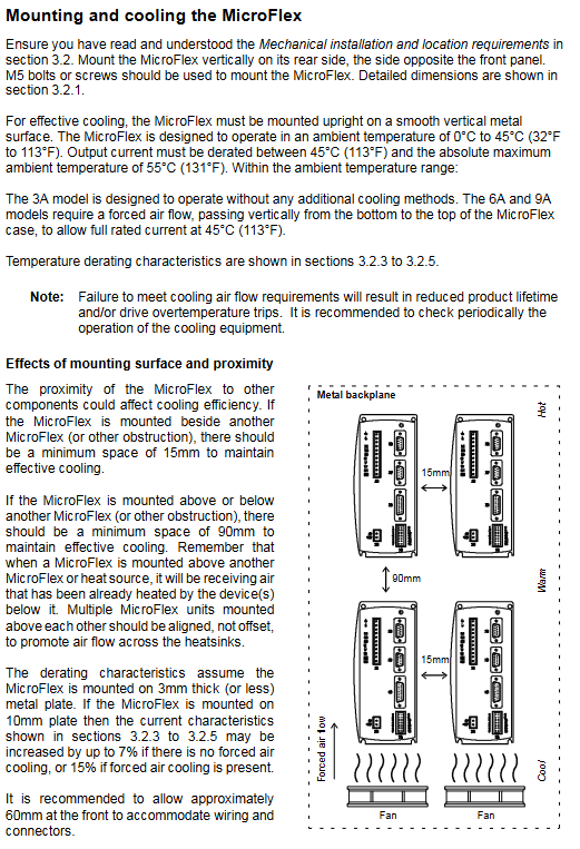
Mechanical installation: Vertically fixed on the metal surface, a 90mm heat dissipation space should be reserved at the top/bottom for single installation, and the spacing between multiple units should be ≥ 13mm. When sharing DC busbars, precise alignment is required to install the busbars.
Electrical connection:
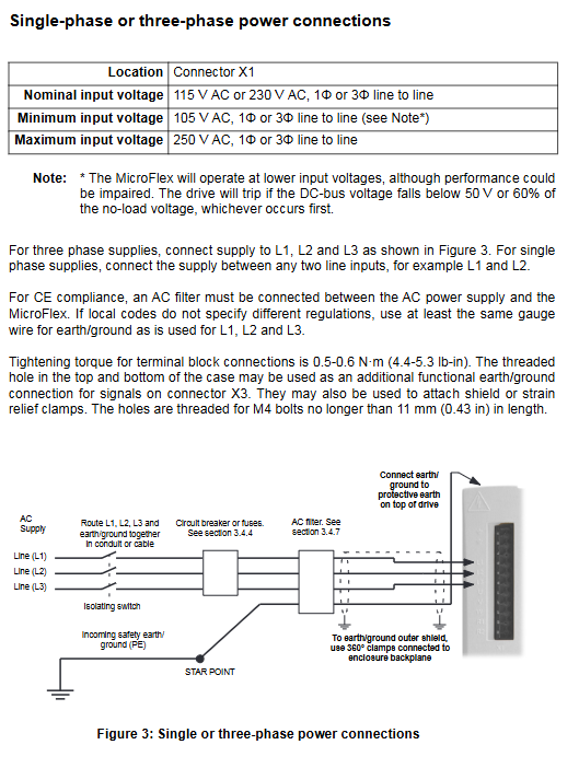
Power connection: The three-phase input is connected to L1/L2/L3, and the PE grounding requires a wire of ≥ 10mm ²; When sharing the DC bus, only the source driver is connected to the AC power supply, and the receiving driver is powered through the bus bar.
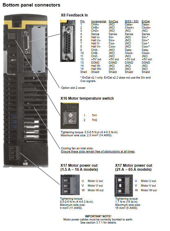
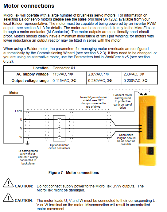
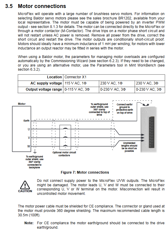
Motor connection: U/V/W corresponds to the motor winding, and the shielding layer is grounded 360 °; The motor circuit can be disconnected through a contactor (the driver needs to be disabled 20ms in advance).
Feedback connection: Connect according to the feedback type (encoder/BiSS, etc.), use twisted pair for signal pairing, single ended grounding for shielding layer, and the longest cable is 30.5m.
Regenerative resistor: minimum 60 Ω for 1.5A/3A model, minimum 15 Ω for 21A/26A model, keep away from flammable materials and reserve heat dissipation space.
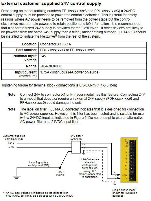
Backup power supply for control circuit: optional 24VDC input (20-30VDC, 1.2A maximum current), used to retain position/I/O information when AC power is cut off.
3. Operation and Configuration
3.1 Software Operation
Software installation: Install Mint Machine Center (MMC) and Mint WorkBench v5.5, supporting Windows XP/Vista/7 systems.
Debugging process:
Connect the PC to the driver (USB/Ethernet) and install the USB driver (Windows auto recognize).
Start the Commissioning Wizard, select the motor model, configure the control mode (position/speed/torque), and set the scaling factor (such as revolutions per degree).
Run Autotune Wizard to automatically tune (with or without load) and optimize current/speed/position loop parameters.
Perform test movement: jog (JOG (0)=10), relative positioning (MOVER (0)=10+GO (0)), monitor status through Spy window.
3.2 Core Function Configuration
DC bus sharing: The source driver needs to be configured with a “Power Ready” output, and the receiving driver needs to be configured with the corresponding input. A specified inductor (such as a 1.5A model with 1.2mH) needs to be installed.
Control mode:
Position control: Supports preset movement, electronic gear, origin regression, and configurable tracking error threshold.
Speed control: Set the speed through analog input or communication, and support PID regulation.
Torque control: It should be noted that the motor may overspeed when there is no load, and the maximum speed should be limited.
Digital I/O configuration: High speed input can be set as pulse/direction or fast position capture, and output can be set as motor brake control, fault indication, etc.
4. Troubleshooting and Safety Standards
4.1 Common fault handling
Troubleshooting direction
Status LED flashes red to check for error codes (e.g. 3 flashes=overcurrent), locate using the Error Log tool
Communication failure check USB/Ethernet cable, confirm IP configuration (Ethernet default 192.168.100.xxx)
CANopen bus fault confirmation: Terminal resistance (120 Ω), consistent baud rate for all nodes, unique node ID
4.2 Safety Regulations
It must be operated by professional personnel. After power failure, wait for 5 minutes for discharge before touching the power terminal.
The wiring complies with NEC/CE standards, with separate wiring for power and control lines, intersecting at a 90 ° angle, and the shielding layer reliably grounded.
The working temperature of the regenerative resistor may exceed 80 ℃, and it should be kept away from flammable materials; The motor brake requires an independent 24VDC power supply to avoid noise interference.
5. Summary of Technical Specifications
Category key parameters
Power supply input three-phase 230-480VAC (180-528VAC range), DC bus voltage 325V (230V input)/678V (480V input)
Output characteristics: Continuous current of 1.5A-65A, output frequency of 0-2000Hz, switching frequency of 4/8/16kHz (some models)
Feedback accuracy incremental encoder supports up to 8MHz, absolute encoder supports multi turn positioning
Environmental protection: shock resistance of 10G, vibration resistance of 1G (10-150Hz), storage temperature -40-85 ℃
Model and basic information: Baldor FDH1A05TB-EN20 FlexDrive II AC servo drive, priced at $1895.00, with 3 units in stock, in excellent condition, suitable for speed, current, and position control of single axis rotating systems.
Core Features:
Power supply support: 115VAC single-phase, 230VAC single/three-phase, 230-460VAC three-phase (depending on the model).
Current specification: Continuous current of 2.5A-27.5A, peak current of twice the rated value (continuous for 1.25-2.4s).
I/O configuration: 8 optically isolated digital inputs, 3 optically isolated digital outputs, 1 analog input, and 1 relay output.
Communication interface: RS232/RS485 optional, supports MODBUS protocol, and some models support CANopen/DeviceNet/Profibus.
Applicable scenarios: Variable speed three-phase brushless AC motor control for industrial fixed equipment, prohibited for use in household appliances, medical equipment, mobile carriers, and other scenarios.
2. Installation process
2.1 Installation Preparation
Environmental requirements: temperature 0-40 ℃ (with a 2.5% reduction in capacity for every 1 ℃ increase in temperature between 40-50 ℃), relative humidity<90% (non condensing), altitude ≤ 1000m (with a 1.1% reduction in capacity for every 100m exceeding 1000m).
Hardware requirements:
Equipment/tool specification requirements
Minimum PC: Pentium III 500MHz, 128MB RAM, 50MB hard disk space; Recommendation: Above 1GHz, 1GB RAM
Cable motor power line (shielded twisted pair, up to 30.5m), feedback cable (shielded twisted pair, 22AWG or above)
Tools: Small screwdrivers below 3mm, M5 bolts, crimping tools
Other regenerative resistors (7.5A and above models require external installation), EMC filters (required for CE compliance)
2.2 Key Connection Steps
Mechanical installation: Vertically fixed on a non flammable surface, leaving 50mm of heat dissipation space at the top/bottom, and installed side by side with a spacing of ≥ 13mm.
Electrical connection:
Power connection: Single corresponding L/N terminals, three-phase corresponding L1/L2/L3 terminals, must be reliably grounded.
Motor connection: The U/V/W terminals correspond to the motor winding, and it is necessary to distinguish the cable pin configuration of rotary/linear motors.
It must be operated by professionals. Before operation, disconnect the high-voltage power supply and confirm reliable grounding.
The wiring must comply with NEC/CE standards, with separate wiring for power and control lines, intersecting at a 90 degree angle.
Regenerated resistors may generate high temperatures, keep away from flammable materials; Even if the motor circuit is shut down, there may still be high voltage present.
5. Summary of Technical Specifications
Category key parameters
Power input single-phase 115VAC (75-125V), 230VAC (75-250V); Three phase 230V (75-253V), 230-460V (75-528V)
Output characteristics: Output voltage 0-corresponding to input voltage, output frequency 0-500Hz, switching frequency 8kHz
Feedback accuracy Resolver: 14 bits, ± 3 counts; Encoder: up to 4096PPR
Environmental protection with impact resistance of 10G and vibration resistance of 1G (10-150Hz)
Installation requirements: Maintain a safe distance from flammable materials, with a distance of ≥ 50mm above and ≥ 26mm on both sides
Configuration and Debugging Process
(1) Software Tools
Essential software: WorkBench v5 (supporting Windows 95 and above systems)
Hardware requirements: PC requires Intel Pentium 133MHz processor, 32MB memory, 24MB hard drive, serial port (RS232/RS485)
Core functions: Commissioning Wizard, Fine tuning, Parameters, Scope
(2) Debugging steps
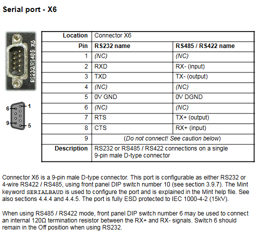
Hardware connection: The PC is connected to the driver through a serial port cable (X6 interface), and the 24VDC control power supply and main circuit power supply are connected
Software startup: Install WorkBench v5, create a new project, scan and connect drives
Wizard configuration: Use the Commissioning Wizard to select the control mode, motor model, and feedback type, and automatically complete parameter tuning
Fine tuning optimization: Adjust the gain of the current/speed/position loop using Fine tuning tools and perform testing motion to verify performance
Parameter saving: Save configuration parameters to the non-volatile memory of the drive to avoid power loss
(3) Control mode description
Control mode signal source, core purpose, key parameters
Torque control analog input/software command constant torque output scenario torque constant, current loop gain (KIPROP/KINET)
Speed control analog input/software instruction constant speed operation scenario speed loop gain (KVPROP/KVINT), acceleration/deceleration time
Position control pulse+direction input precision positioning scene electronic gear ratio (FOLLOWNUMERATOR/BOLLOWDENOM)
Troubleshooting and Maintenance
(1) Fault indication and handling
Key points for troubleshooting status LED fault types
Red flashing (1-11 times) corresponds to error codes (1=bus overvoltage, 3=overcurrent, etc.). Check AXISOROR/DRIVEERROR parameters and wiring/load
Red green alternating flashing undervoltage warning. Check if the main circuit power supply is connected and if the DC bus voltage is ≥ 50V
Check the wiring of the 24VDC power supply to ensure that the voltage is within the range of 20-30V when the control power supply fails to light up
(2) Common problem solving
Communication failure: Confirm that the PC serial port selection is correct, use the “scan all serial ports” function, and check the serial port cable wiring
Driver unable to enable: Check if the X3 interface driver enable signal (6/7 pins) is valid and clear the fault status
Motor instability: Reduce the speed loop proportional gain (KVPROP) and confirm that the current loop parameters match the motor
(3) Maintenance points
Regular inspection: Check if the heat dissipation duct is unobstructed, if the temperature of the braking resistor is normal, and if the cable shielding layer is intact
Cable maintenance: The distance between feedback cables and power cables should be ≥ 76mm, avoiding parallel wiring and maintaining a 90 ° angle when crossing
Software maintenance: Regularly backup drive configuration parameters and collect system information using the SupportMe feature
Accessories and Compliance Information
(1) Key accessories
Accessory type, model, example, function, and purpose
Cooling fan FAN001-024 provides forced air cooling for 6A/9A models, with an input of 23-27.5VDC
EMC filter FI0015A00 suppresses electromagnetic interference and complies with CE directive requirements
Regenerative resistors RG56/RG39 consume braking energy to avoid bus overvoltage
Special cable CBL030SP-MHCE motor power cable/feedback cable, with shielding layer
(2) Compliance requirements
CE compliance: EMC filter needs to be installed, motor cable length ≤ 30m, shielding layer grounded 360 °
EMC compliance: Complies with EN61000-6-3 (residential/commercial environment) and EN61000-6-4 (industrial environment) standards
Wiring requirements: Power cables and control cables should be arranged separately, intersecting at a 90 degree angle to reduce electromagnetic interference
Requirements for Capacity Reduction: Capacity reduction is required in free air environments (for 100W models, capacity reduction is required at 25 ℃ to 80% and 55 ℃ to 70%)
Configuration and Debugging Process
(1) Software Tools
Essential software: Mint WorkBench (supporting Windows XP and above systems)
Hardware requirements: The PC requires a 1GHz processor, 512MB of memory, 2GB of hard drive, and a serial port (RS232/RS485)
Core functions: Commissioning Wizard, Fine tuning, Parameters, Scope
(2) Debugging steps
Hardware connection: The PC is connected to the driver through a serial port cable (X6 interface), and the 24VDC control power supply and main circuit power supply are connected
Software startup: Install Mint WorkBench, create a new project, scan and connect drives
Wizard configuration: Use the Commissioning Wizard to select the control mode, motor model, and feedback type, and automatically complete parameter tuning
Fine tuning optimization: Adjust the gain of the current/speed/position loop using Fine tuning tools and perform testing motion to verify performance
Parameter saving: Save configuration parameters to the non-volatile memory of the drive to avoid power loss
(3) Control mode description
Control mode signal source, core purpose, key parameters
Torque control analog input/software command constant torque output scene torque constant, current loop gain
Speed control analog input/software instruction constant speed operation scenario speed loop gain, acceleration/deceleration time
Position control pulse+direction input precision positioning scene electronic gear ratio, position loop gain
Troubleshooting and Maintenance
(1) Fault indication and handling
Key points for troubleshooting status LED fault types
Red flashing (1-12 times) corresponds to error codes (1=phase search error, 3=overcurrent, etc.). Check AXISOROR/DRIVEERROR parameters and wiring/load
Red green alternating flashing undervoltage warning. Check if the main circuit power supply is connected and if the DC bus voltage is ≥ 50V
Check the wiring of the 24VDC power supply to ensure that the voltage is within the range of 20-30V when the control power supply fails to light up
(2) Common problem solving
Communication failure: Confirm that the PC serial port selection is correct, use the “scan all serial ports” function, and check the serial port cable wiring
Driver unable to enable: Check if the X3 interface driver enable signal (6/7 pins) is valid and clear the fault status
Motor instability: Reduce the speed loop proportional gain (KVPROP) and confirm that the current loop parameters match the motor
(3) Maintenance points
Regular inspection: Check if the heat dissipation duct is unobstructed, if the temperature of the braking resistor is normal, and if the cable shielding layer is intact
Cable maintenance: The distance between feedback cables and power cables should be ≥ 76mm, avoiding parallel wiring and maintaining a 90 ° angle when crossing
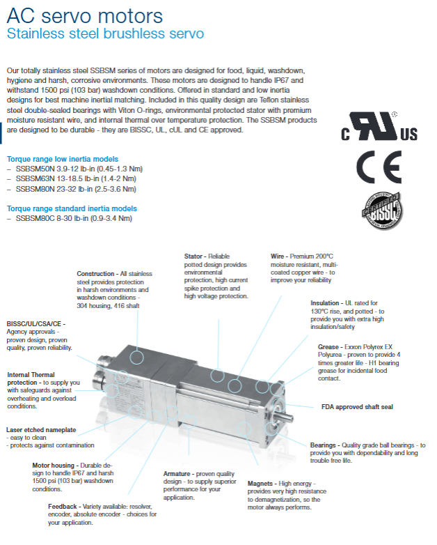
1、 Comparison of core product line parameters Product Series Inertia Characteristics Torque Range (Nm) Speed Range (rpm) Protection Level Core Advantages Applicable Scenarios BSM N series low inertia 0.45-40 1200-10000 IP54 (IP55 with shaft seal) high dynamic response, excellent acceleration performance, precise positioning, high-speed transmission BSM C series high inertia 1.2-134 1200-10000 IP54 (IP55 with shaft seal) has good load matching, strong economy, inertia load, and continuous operation SSBSM series low/standard inertia 0.45-3.6 (N-type); 0.9-3.4 (Type C) 4000-10000 IP67 all stainless steel, corrosion-resistant and washable for food processing and hygiene scenarios BSM25/33 series standard inertia 2.1-15.6 1800-7000 IP54 circular shell, foot/flange dual installation portable device, universal automation 2、 Key technical characteristics (1) Power performance Torque output: BSM N series peak torque is 4 times continuous torque, C series is 3 times, meeting high acceleration requirements Speed adaptation: Rated speed of 1200rpm to 9000rpm at 320Vdc, doubled speed at 640Vdc (maximum speed limit to be confirmed) Dynamic response: Mechanical time constant as low as 0.24ms (BSM100C series), supporting fast positioning (2) Structure and Protection Material and process: neodymium iron boron magnetic steel, epoxy resin encapsulated winding, galvanized hardware, SSBSM adopts 304 shell+416 axis Protection design: basic IP54, IP55 after shaft seal configuration, SSBSM up to IP67, resistant to 1500psi (103bar) flushing Temperature adaptation: ambient temperature -29 ℃ -40 ℃, maximum winding temperature 155 ℃, no derating at 1000m altitude (3) Feedback and Control Feedback options: Resolver (anti-interference), Incremental Encoder (1000/2500ppr), Absolute Encoder (BiSS/OnDet/SSI/Hiperface), Hall Sensor Control adaptation: Supports torque/speed/position modes, compatible with EtherCAT/POWERLINK/Modbus TCP protocols Safety protection: built-in thermal switch (155 ℃± 5 ℃ action), overcurrent protection, anti
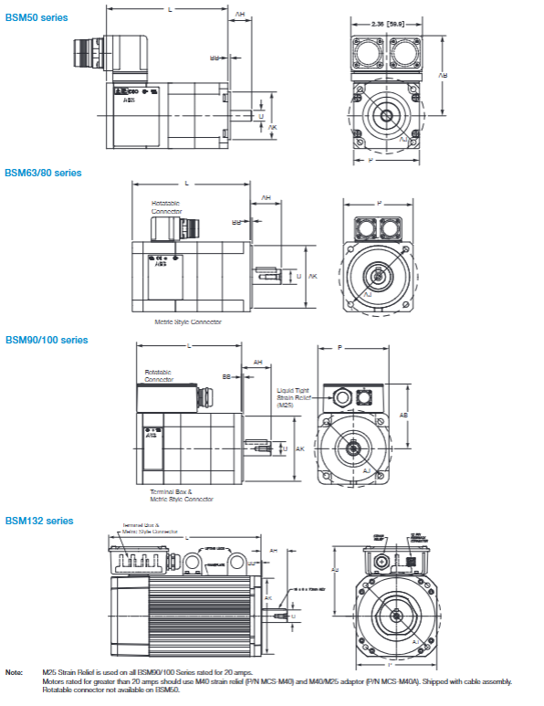
demagnetization design 3、 Supporting drive and control scheme Driver series input voltage output current (RMS) control protocol adapted to motor core functions MicroFlex analog 105-250VAC (1/3 phase) 3A/6A/9A analog/pulse direction BSM N/C series (low power) automatic tuning, anti resonance filtering MicroFlex e150 105-250VAC (1/3 phase) 3A/6A/9A EtherCAT/Ethernet/IP All Series Small Power Models Safe Torque Off (STO), Dual Encoder MotiFlex e180 200-480VAC (3-phase) 3A-90A EtherCAT/POWERLINK full series (including BSM132C) 300% overload, multi axis synchronization Control software – DriveSize+MCSize selection calculation tool 4、 Installation and Dimensional Specifications (1) Installation standards IEC framework: 50/63/80/90/100/132, shaft diameter range 9mm-38mm NEMA Framework: 23 (BSM50N), 34 (BSM63N), 42 (BSM80N/C), 56 (BSM90/100N/C) Compatible accessories: flange adapter kit, strain relief (M25/M40), rotary connector (2) Example of Critical Dimensions (IEC) Motor model, frame length (without brake, mm), shaft diameter (mm), installation hole spacing (mm) BSM50N 50 101.7-179.5 9 63 BSM80C 80 144.0-220.2 19 100 BSM132C 132 384-536.4 38 265 5、 Selection and Engineering Support (1) Selection calculation process Load analysis: Calculate load inertia, friction torque, and acceleration torque Inertia matching: The recommended ratio of motor inertia to load inertia is 1:1-1:5 Torque calculation: RMS torque=√ [(acceleration torque ² x acceleration time)+(operating torque ² x operating time)+(deceleration torque ² x deceleration time)]/(total time) Voltage selection: Match the bus voltage of 160Vdc/320Vdc/640Vdc according to the target speed (2) Engineering resources Technical documents: 2D/3D CAD files, wiring diagrams, performance curves Conversion tool: Inertia/torque/length/power unit conversion table Compliance certification: CE/UL/cUL/BSC/RoHS/WEEE, SSBSM additionally obtained FDA food contact certification
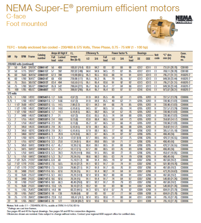
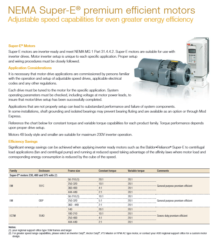
1、 Product System Overview The document revolves around Baldor Rebellion ® NEMA Super-E ® Series of high-efficiency motors developed with NEMA Premium ® The core selling point is energy efficiency, covering the power range of 0.18kW-300kW (1/4Hp-400Hp), providing two types of protection: TEFC (fully enclosed fan cooling) and ODP (open anti drip). It is suitable for single-phase 115/230V, three-phase 208-230/460V, 575V and other voltage levels. The frame size extends from 48 and 56 to 449T, including general-purpose and HVAC, refrigeration tower, pump, unit handling and other specialized models, meeting the diverse needs of power transmission, fluid transportation, material handling and other industrial production scenarios. 2、 Core product types and key parameters (1) Comparison of Core Parameters of Universal Motors Protection type, phase power range, voltage level, core characteristics, framework dimensions TEFC single-phase 0.18-3.7kW (1/4-5Hp) 115/230V capacitor start/run, dynamically balanced rotors 48, 56, 143T-184T TEFC three-phase 0.37-300kW (1/2-400Hp) 230/460V, 575V Class F insulation, 1.15 service factor 56, 143T-449T ODP single-phase 0.18-3.7kW (1/4-5Hp) 115/230V open heat dissipation, heavy-duty steel frame 48, 56, 143T-184T ODP three-phase 0.75-300kW (1-400Hp) 230/460V, 575V anti drip structure, rodent screen protection 143T-449T (2) Key configurations for dedicated models HVAC specific motor: Covering TEFC/ODP types, power 0.75-75kW (1-100Hp), compatible with 230/460V, 575V Equipped with AEGIS ® The bearing protection model has Class H insulation and is compatible with variable speed drives Features: Heavy duty steel frame, dynamically balanced rotor, installation in any direction Refrigeration tower/chiller motor (TEAO): Power 3.7-56kW (5-75Hp), 230/460V three-phase Protection: Epoxy anti-corrosion coating, double sealed bearings, moisture-proof winding Adaptive airflow speed: 1200-2000ft/min Pump motor: Direct connection design, including TEFC/ODP type, power 0.75-37kW (1-50Hp) Equipped with AEGIS ® Grounding ring type: Class H insulation, oversized bearings, suitable for speed regulation scenarios Vertical P-base model: capable of withstanding normal thrust, suitable for sewage treatment and irrigation pumps Unit handling motor: Power 0.37-7.5kW (1/2-10Hp), 208-230/460V, 575V D series brake model: spring brake, manual release lever, suitable for conveyors and elevators 200V dedicated motor: Covering TEFC/ODP types, with a power of 0.75-75kW (1-100Hp) Features: Cast iron frame, locking end bearings, suitable for special power supply scenarios (3) Range of key performance parameters Performance indicator range standard configuration Efficiency level meets NEMA Premium standards ® Standard across the entire series Insulation Class F (some specialized models Class H) for all models Service coefficient 1.15 (1.0 for some brake models) standard for general models Multiple speeds available: 900RPM, 1200RPM, 1750-1780RPM, 3450-3560RPM Warranty period of 3 years (841XL series 5 years) Full range guarantee
3、 Core Technology and Design Features Energy Efficiency and Electrical Design: Meet NEMA Premium requirements ® Energy efficiency standards to reduce lifecycle energy consumption 200 ° C inverter peak protection insulation system, compliant with NEMA MG1 Part 31.4.4.2, compatible with frequency converters Silicon free wires, anti corona testing to enhance electrical stability Mechanical and protective design: Standard Mobil Polyrex ® EM grease has a lubrication life four times longer than ordinary grease and can withstand high temperatures up to 176 ° C Cast iron/heavy-duty steel frame, galvanized hardware, TEFC model with anti-corrosion epoxy coating Dynamically balanced rotor, vibration peak<38.1mm/s (some models<2.03mm/s) Installation and adaptability: Supports various methods such as foot installation, C-face installation, and footless installation The frame size is compatible with NEMA standards, and some models can adapt to multi frame installations of 56, 143T, and 145T Suitable for high altitude (>3300 feet), high and low temperature (-60 ° C to>40 ° C) environments 4、 Customization and accessory options (1) Main customized projects Electrical customization: special voltage (such as 200V), thermal protection (thermostat/thermistor), special winding types Mechanical customization: insulated bearings, stainless steel shafts, sliding bases, customized shaft diameters/lengths Environmental adaptation: anti-corrosion coating, high-altitude calibration, low-temperature start-up optimization Function expansion: brake, encoder, speedometer, enlarged junction box (2) Core accessories Protection category: AEGIS ® Bearing protection ring, space heater, dust seal Detection category: BEI/Avtron encoder, XPY DC speedometer Connection type: cast iron junction box, terminal board, extension conduit Braking type: Dodge “D” series spring brake (torque 2.87-23.94Nm) 5、 Authentication and Application Scenarios Certification qualifications: UL/CSA certification, CE certification, in compliance with NEMA standards, some models have passed ASTM B117-90 96 hour salt spray test Core application: General industries: machine tools, conveyor belts, compressors, blowers Architecture and HVAC: ventilation fans, air conditioning units, heat pumps Fluid processing: water pump, oil pump, refrigeration tower, chiller Material handling: luggage conveying, elevators, cranes, packaging equipment
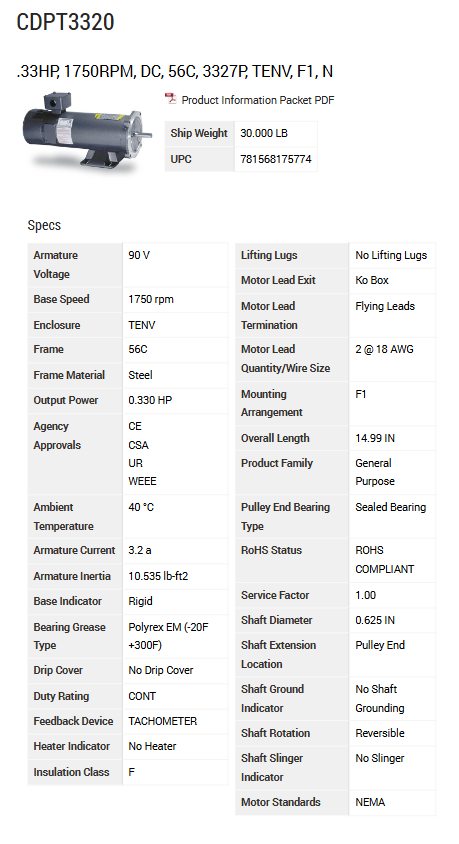
The document revolves around Baldor Rebellion ® The brand’s overall horsepower DC motor is deployed, covering a power range of 1-500Hp, with voltage levels including 180V, 240V, 500V, etc. The protection levels include drip proof full protection (DPFG), fully enclosed no ventilation (TENV), fully enclosed fan cooling (TEFC), etc. The core is adapted to the power transmission needs of industrial scenarios and supports customized modifications to meet different environmental and working conditions.
Main product types and parameters
(1) Ordinary DC motor
Motor type, power range, armature voltage, core characteristics, applicable scenarios
Drip proof full protection (DPFG) 1-500Hp 180V, 240V, 500V 20:1 constant torque speed range, Class F insulation universal industrial transmission
Fully enclosed non ventilated (TENV) 1-40Hp 180V, 240V, 500V dustproof and moisture-proof, compact structure, clean environment
Fully enclosed fan cooling (TEFC) 2-75Hp 240V, 500V forced air cooling, continuous operation in harsh environments for long-term operation
(2) Short time rated motor
Power range: 1-150Hp (240V), 3-500Hp (500V)
Rated duration: 1 hour, 30 minutes, 15 minutes
Core requirement: The winding temperature should be close to the ambient temperature (± 5 ° C) when starting, and the excitation voltage should be cut off when not in operation
(3) Specialized motor
Paper mill service motor: supports Class F/B temperature rise level, with special configurations such as splash proof cover and transparent handhole cover, with a power of 7.5-500Hp
Range driven motor: 240V armature, 240V excitation, compatible with multi motor drive systems, power 3-50Hp
Extruder specific motor: anti drip protection forced ventilation, including fiberglass filter, warning thermometer, power 10-400Hp
IEC DC motor: 460V armature, 310V excitation, IP23 protection, power 15.9-396kW
(4) Generator products
DC generator: 120V, 250V and other voltages, fully protected against dripping, power 0.75-170kW
Enhance magnetic generator: 230VDC output, Class H insulation, power 5-40kW, suitable for lifting scenarios
Core technical characteristics
General standards: Class F insulation level, 40 ° C ambient temperature adaptation, 1.0 service factor, direct excitation winding (partially stable direct excitation)
Structural design: commutator end locking bearing, accessory installation surface, standard shaft diameter and length (customizable)
Speed regulation performance: Ordinary motors support 20:1 constant torque speed regulation, and short-term rated motors are suitable for different load duration requirements
Protection capability: Explosion proof motors comply with Class I/II hazardous environment standards, and paper mill motors have anti-corrosion and anti drip characteristics
Customized modifications and accessories
(1) Main modification items
Environmental adaptation: High altitude (>3300 feet), high temperature (>40 ° C), low temperature (as low as -60 ° C)
Compatible power supply: Supports 230V/460V AC input, full wave rectification power supply, NEMA Type C/D standard
Industry Scenarios: Paper Mill (Wet End Operation), Lumber (Rapid Acceleration and Deceleration Requirements), Extruder (High Temperature Environment), General Industrial Transmission
This document focuses on Baldor brand sports product accessories, covering core categories such as HMI panels, various cables, 24V DC DIN rail power supply units, EMC filters, encoder distributors, etc. All accessories are specifically designed to fit Mint under Baldor ® The design of main products such as programmable motion controllers and servo drives has the characteristics of strong compatibility, stable performance, and easy installation, which can meet the diverse equipment connection, control, and data transmission needs in industrial automation scenarios, and provide global technical support and product consulting services.
HMI panel
(1) Core positioning and connection method
Baldor’s HMI panel (human-machine interface) serves as a key interaction hub between the machine and the operator, and can seamlessly interface with the Mint motion controller through the controller’s RS232 interface or optional CANopen interface (with KPD-OPTC tab installed). Its core advantage lies in the efficient data transmission achieved through the Mint Comms Array (a dedicated storage area in the controller memory), which supports read and write operations of up to 99 data elements. The preset elements can directly present key data such as digital I/O information, axis position, and fault alarms, greatly simplifying the process of equipment status monitoring and parameter adjustment.
(2) Product classification and technical parameters
1. Text display
Basic features: Adopting a reflective LCD screen, in addition to displaying text of different sizes, it also supports simple graphic display, equipped with a data input keyboard and programmable macro keys. Through the keyboard macro editor, a series of instructions such as page flipping, parameter setting, LED switching, etc. can be executed with a single key, without the need for additional programming, making the operation convenient. The LCD display screen can expand the display of data visualization forms such as bitmap, bar chart, trend chart, etc. All functions are programmed and configured through Designer software.
Core model parameters (representative models):
|Model | Display specifications (rows/columns) | Resolution | Number of function keys | numeric keypad | LED status indicator | User memory | Alarm capacity | Protection level | Maximum power consumption (24VDC) | Dimensions (HxL, mm) | Installation opening (LxH, mm)|
Common configuration: All models support 256 user-defined fonts, equipped with 1 CANopen auxiliary port, and the serial port baud rate can be selected as 38400 or 9600; Some high-end models (such as KPD-KG840-10) have printer ports, real-time clock, and battery power supply functions, support 16KB recipe memory, and can store device operating parameter templates to meet multi scenario switching needs.
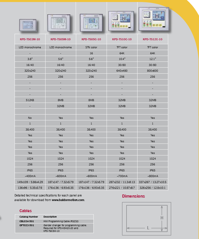
2. Graphic touch screen
Basic features: Covering entry-level to high-end application scenarios, with sizes ranging from 3.8-inch monochrome screens to 12.1-inch full-color TFT screens, resolution range from 320×240 to 800×600, capable of displaying complex graphics, dynamic interfaces, and high-definition data charts. Support formula data storage function, able to save multiple machine configuration parameters for quick calling and switching; The screen can customize touch areas (touch units), respond to human touch operations, and can be programmed to achieve functions such as data input, page switching, and scrolling display.
Core model parameters (representative models):
|Model | Display Type | Size | Color Depth | Display Specifications (Rows/Columns) | Resolution | User Memory | Extended Memory | Real time Clock | Alarm Capacity | Protection Level | Maximum Power Consumption (24VDC) | Dimensions (HxL, mm) | Installation Openings (LxH, mm)|
Common configuration: All touch screens support 256 user-defined fonts, with a fixed serial port baud rate of 38400 and equipped with one CANopen auxiliary port; Support password protection function, set operation permissions to prevent accidental operation; Built in 256 event lists for easy device fault tracing and operational status analysis.
(3) Programming software and functional support
Baldor has developed a Windows based Designer software specifically for HMI panels, which serves as a unified programming tool for the entire range of panels, greatly reducing training, development, and maintenance costs. Its core functions include:
Visual editing: Adopting WYSIWYG (what you see is what you get) editing mode, the design effect on the computer screen is completely consistent with the actual display of the panel, and the placement and editing of elements such as text, variables, graphics, touch buttons, etc. are intuitive and efficient.
Rich resource library: Built in 500+professional symbol libraries, which can be directly called to quickly build interfaces; Support custom graphic creation, or import image files in more than 20 formats such as BMP, JPEG, TIFF, etc., to meet personalized interface design needs.
Multilingual translation: Project text, alarm information, operation prompts, etc. can be exported to Microsoft Excel and other office software for multilingual editing. After editing, the project file can be imported, and the graphic layout remains intact without the need for readjustment.
Object oriented workflow: Screen images exist in the form of objects, supporting movement, copying, editing, alignment, and combination operations. Custom graphics can be saved to the project library for easy reuse in subsequent projects.
Touch unit programming: The touch area can be defined by software drawing or importing graphic files, combined with a keyboard macro editor, to achieve complex logic control and operation response, and even overlay touch layers on animated drawings, providing efficient tools for equipment troubleshooting.
Software acquisition: HMI Designer software can be applied for evaluation and use through the Baldor official website (www.baldormotion. com), and detailed programming tutorials and technical documents can also be downloaded from the platform.
Cables and connectors
(1) Product classification and usage
Baldor’s cable product system is complete, covering four categories: motion feedback cables, motor power cables, communication cables, and programming cables, all tailored to fit its servo motors, drivers, and motion controllers. It provides two forms of cables: prefabricated products (with connectors) and original cables (without connectors). Some cables support customized lengths to meet the needs of different installation scenarios
1. Motion feedback cable
Classification and Applications: This includes encoder cables, EnDat cables, Resolvers (rotary transformers) cables, and SSI cables, which correspond to different types of feedback signal transmission requirements. They are suitable for signal connections between Baldor Series II drives, MicroFlex drives, NextMove series motion controllers, and servo motors.
Key specifications:
Encoder cable: Models represented by CBLxxxRF-E (without connectors), CBLxxxSF-E (with connectors at both ends), etc., with a wire diameter of 8.9mm (0.35 inches) and a 16 core wire design;
EnDat cable: Models represented by CBLxxxRF-D (without connector) and CBLxxxSF-D (with motor end connector), with a wire diameter of 8.65mm (0.34 inches) and an 11 core wire design;
Resolver/SI cable: Resolver cable diameter 8.2mm (0.32 inches), 7-core wire; SSI cable supports connection to both ends of MicroFlex driver (model CBLxxxSF-S2);
Suitable for special motors: When used for Baldor stainless steel servo motors (SSBSM), an “S” symbol should be added after the model, such as CBL025SF-E1S.
2. Motor power cable
Core parameters: Divided into four specifications based on rated current: 12A, 20A, 35A, and 50A, corresponding to wire diameters of 10.8mm (0.43 inches), 12.7mm (0.5 inches), 19.2mm (0.76 inches), and 22.8mm (0.9 inches), respectively;
Model examples: CBLxxxRP-12 (12A without connector), CBLxxxSP-20 (20A with motor end connector, model CBLxxxSP-20S when compatible with SSBSM motor);
OPT033-501: Programming cable gender converter, an essential accessory for KPD-KG420-20 and KPD-TS03M-10 HMI panels;
Ethernet/CAN cable: designed specifically for Baldor e100 product series and CAN I/O nodes with RJ45 interface, using CAT5e shielded wires and RJ45 connectors. Core models include CBL002CM-EXS (0.2m/8 inches), CBL005CM-EXS (0.5m/1.6 feet), CBL010CM-EXS (1m/3.2 feet), CBL020CM-EXS (2m/6.5 feet), CBL050CM-EXS (5m/16.3 feet), and CBL100CM-EXS (10m/32.6 feet). The shielding design effectively reduces electromagnetic interference and ensures data transmission stability.
4. Motor connector
Suitable for use with original cables, providing two types of power connectors and feedback connectors:
|Model | Purpose | Suitable Motor Type|
|MCSPOW-08 | Power connector (compatible with BSM 50/63/80 motors) | Ordinary servo motor|
|MCSPOW-08S | Power connector | Stainless steel servo motor (SSBSM)|
Baldor motor feedback cables and power cables are designed specifically for high flexibility application scenarios, with excellent bending resistance and resistance to high and low temperatures. The specific parameters are as follows:
Specific parameters of characteristic indicators
Working temperature range bending state: -30 ℃ to 80 ℃; Fixed state: -50 ℃ to 90 ℃
The static bending radius is approximately 7.5 times the diameter of the cable
The dynamic bending radius is approximately 10 times the diameter of the cable
The minimum bending life under rated conditions shall not be less than 2 million times
Maximum operating speed 3m/s (9.8 feet/s)
Maximum acceleration 7m/s ² (0.7G)
Additional explanation: Detailed technical parameters of 35A and 50A specification power cables need to be obtained by contacting Baldor official.
24V DC DIN rail power supply unit
(1) Core positioning and product features
This series of power supply units is designed specifically for Baldor motion controllers, servo drives, and HMI panels. It outputs a stable 24V DC voltage and adopts a DIN rail installation method (compatible with TS35/7.5 or TS35/15 specification rails). It has the following core features:
Wide input range: Some models support 85-264VAC wide voltage input, compatible with global voltage standards of 110-230VAC, and also support 120-370VDC DC input, suitable for different power supply environments;
High efficiency and low consumption: conversion efficiency up to 84%, low operating temperature, excellent heat dissipation performance;
Low interference: Built in EMI filter with low ripple noise (minimum 80mV), reducing electromagnetic interference to other devices;
Multiple protection: equipped with short-circuit protection, overload protection, overvoltage protection, and temperature protection functions to ensure the safe operation of equipment;
Compact and lightweight: With a small size and a minimum weight of only 0.55kg, it saves space for installing control cabinets.
(2) Core model technical parameters
Model Input Voltage Range Output Specification Output Power Conversion Efficiency Ripple Noise Overload Protection Range Overvoltage Protection Range Operating Temperature Range Dimensions (HxLxD, mm) Weight
According to the device configuration requirements, the following selection criteria can be used to select the appropriate power supply unit:
Power model adaptation system configuration (HMI+NetMove controller+number of servo axes)
DR-75-24 1 HMI+1 controller+3 servo axes
DR-120-24 1 HMI+1 controller+5 servo axes
DRP-240-24 1 HMI+1 controller+9 servo axes
(4) Safety and Compliance Standards
Safety standards: comply with UL508 and TUV EN60950 certification standards;
EMC standard: meets EN55022 Class B、EN61000-3-2、EN61000-3-3、EN61000-4-2/3/4/5/6/8/11、ENV50204 According to standards, it has excellent electromagnetic compatibility.
Other core accessories
(1) Encoder allocator
Function positioning: Receive a single encoder input signal (usually from the main encoder) and distribute the signal to multiple drivers or motion controllers, suitable for multi device collaborative control scenarios, simplifying encoder signal wiring.
Core model:
|Model | Number of Channels | Installation Method|
|OPT029-501 | 4-channel | DIN rail installation|
|OPT029-502 | 8-channel | DIN rail installation|
(2) EMC filter
Function positioning: Designed specifically for Baldor servo drives and motion controllers to suppress electromagnetic interference and ensure stable operation of equipment in complex electromagnetic environments; The single-phase driver is compatible with a bottom mounted filter (model identification marked with “*”), which can effectively save control cabinet space.
Core positioning: Designed specifically to evaluate the usability and flexibility of the HICore 1 security SoC (HTPC1301 A0), while serving as an application software development platform during the target hardware design phase, in line with the HIMA “intelligent security” concept, pre installed with reference applications, ready to use out of the box.
Core hardware parameters:
Processor: DP80390 8-bit processor, high energy efficiency, maximum clock frequency of 100MHz
Power consumption mode: Supports APL power levels A (540mW) and C (1100mW)
Security features: Integrated watchdog, secure operating system, communication module, with on-chip redundancy
Working temperature: -40 ° C to+85 ° C
Safety certification: certified by IEC 61508 SIL 3, ISO 13849-1 PLe/Cat. 4, EN 62061
Kit model and core differences
Features HICore 1 Evaluation Board Ethernet APL Security Evaluation Board
Evaluate the full features of HICore 1 in application scenarios, develop universal safety products, evaluate Ethernet APL/SPE safety communication, and develop products that are compatible with PROFIsafe/CIP Safety
Non secure communication – PROFInet *, Ethernet/IP * (requires external network controller)
Delivery Content and Development Environment
Standard Delivery Checklist:
Hardware: Corresponding model evaluation board, 24V switch power supply, anti-static pad
Software: Software packages that comply with security standards (secure operating systems, secure middleware), security manuals, hardware design guidelines
Development tool: DCD HAD2 JTAG debugger
Development environment support:
Compatible software: IAR Embedded Workbench for 8051 (requires authorization)
Digital resources: complete digital documents, security manuals, hardware design guidelines
Optional accessories:
IAR Embedded Workbench authorization, DCD HAD2 kit, RS232/422/485 USB adapter
Core advantages
One stop development: including hardware, software, and tools, no need for additional configuration, quick start of development;
Safety compliance: Both software and hardware have passed the highest SIL 3 safety certification, reducing product certification risks;
Scenario adaptation: Two models respectively cover the development requirements of general security products and Ethernet APL security communication products;
Flexible Expansion: Supports additional I/O configurations and optional accessories to adapt to different development scenarios.