Call us 24/7uaedcs@163.com
Welcome to the official website of CNIACS Automation Technology Co., Ltd!
Call us 24/7uaedcs@163.com

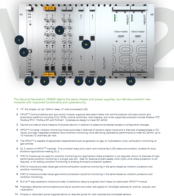
Meggitt VM600 MPS Mechanical Protection System

Meggitt VM600 MPS (Mechanical Protection System) is a modular digital protection system used for monitoring and protecting parameters such as vibration and temperature in industrial rotating machinery. It supports two types of racks, ABE04x (6U) and ABE056 (1U), and is equipped with MPC4/AMC8 core processing cards and IOC4T/IOC8T input/output cards. It has 4-8 measurement channels and 2 speed channels, supports voltage/current signal input, multiple signal processing modes, and alarm logic combinations. It is controlled by OC Bus/Raw Bus extension relays, compatible with RS-232/Ethernet communication, and meets industry standards such as API 670 and IEC 61508. It is suitable for compressors and gas turbines in the fields of power, oil and gas, etc. Waiting for device protection.

Core architecture and hardware composition of the product

1. Rack and power system

Rack model, size, specifications, compatibility, number of power card slots, core features

ABE04x (ABE040/ABE042) 19 “× 6U RPS6U (300W/330W) 21 VME slots (0-20) support redundant power supply and multi module expansion

ABE056 19 “× 1U RPS1U (AC/DC input) 3 VME slots (1, 3, x) slim line design, space saving

Key parameters of power module:

RPS6U: Output+5V (35A/50A), ± 12V, supports AC (115/230V) or DC (24/110V) input

Redundant configuration: Dual RPS6U can achieve power redundancy or power expansion, supporting hot swapping

2. Core functional modules

Module type represents model, core function, key specifications

Vibration protection card MPC4 vibration signal processing, speed monitoring with 4 measurement channels, 2 speed channels, SIL version optional

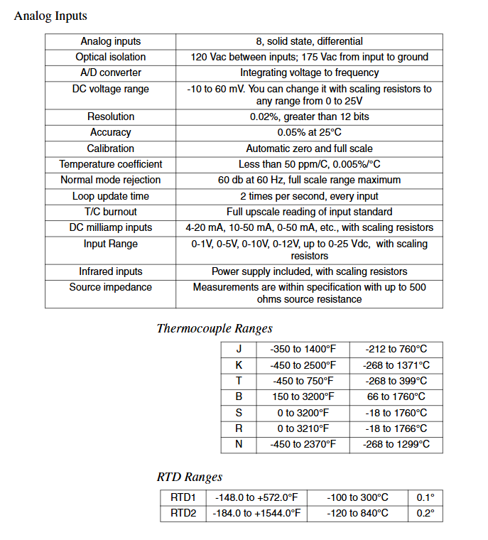
Simulate monitoring card AMC8 for quasi-static parameter monitoring such as temperature and pressure, with 8 measurement channels and support for thermocouple/RTD input

Control card CPUM rack control, network communication support Ethernet/RS-232, Modbus TCP

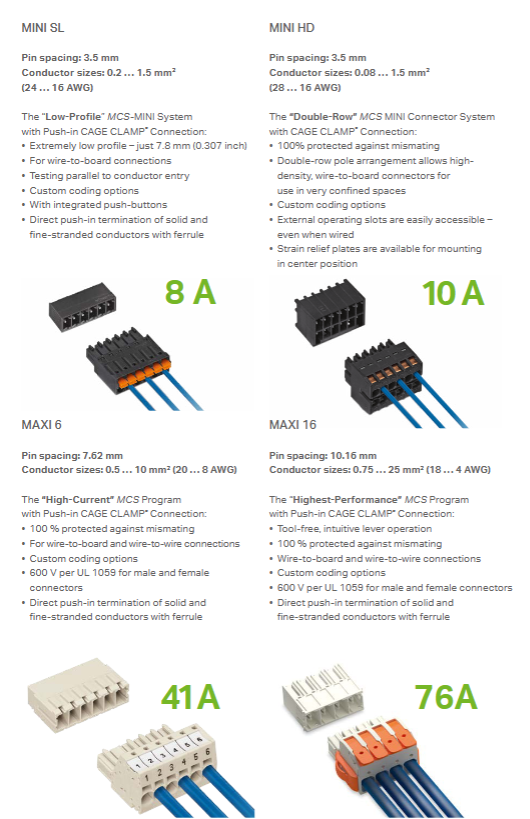
Input/output card IOC4T/IOC8T sensor wiring, signal conversion screw terminal (≤ 1.5mm ² wire diameter), DC output (4-20mA/0-10V)

Relay expansion card RLC16/IRC4 alarm output expansion RLC16 (16 channels), IRC4 (8 channels, supporting DSDT/SPDT)

Signal processing and measurement capabilities

1. Input signal type

Vibration signals: acceleration, velocity, displacement (supporting accelerometers, proximity probes, etc.)

Temperature signal: thermocouple (E/J/K/T type) RTD(Pt100/Cu10/Ni120)

Speed signal: magneto electric sensor, TTL signal (0.3Hz-50kHz)

Other signals: 4-20mA current signal, 0-10V voltage signal (pressure, flow rate, etc.)

2. Core processing mode

Vibration processing: broadband absolute vibration (BBAB), shaft relative vibration (RS), eccentricity (EC), Smax measurement

Temperature/pressure processing: quasi-static measurement, differential measurement, linear compensation

Speed processing: speed calculation, phase reference, trigger threshold adaptive

Rectification method: RMS, mean, peak, peak to peak (supports True Peak/Peak to Peak)

3. Alarm and control functions

Alarm level: Alert+/-, Danger+/- four level alarm

Alarm configuration: Delay (Δ t), hysteresis value, and latch function can be set

Logical combination: Supports 8 basic logics (AND/OR/voting logics) and 4 advanced logical combinations

Control functions: Danger Bypass, Trip Multiply, Channel Inhibit

Extended control: Drive external relays through OC Bus (16 channels) and Raw Bus (64 channels)

Communication and Interface

1. Communication method

Local communication: RS-232 (single card configuration)

Network communication: Ethernet (CPUM module) Modbus TCP/RTU

Bus support: VME bus (in rack module communication), Tacho Bus (speed signal sharing)

Expansion interface: RS-485 (supports half duplex/full duplex)

2. Signal interface specifications

Input terminals: screw terminals (IOC4T/IOC8T), BNC (MPC4 panel, RAW signal output)

Output signal: DC output (4-20mA or 0-10V), relay contact output

Shielding design: Sensor cable shielding grounding, supporting galvanic separation (GSI module)

Installation and compliance requirements

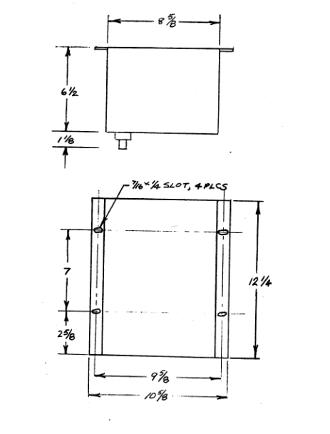
1. Installation specifications

Ventilation requirements: Natural ventilation requires reserved spacing (ABE04x ≥ 50mm, ABE056 ≥ 20mm), and forced air cooling is recommended for high temperature environments

Grounding configuration: Rack grounding (PE), signal shielding grounding, supporting switching between VME grounding and chassis grounding

Hot swappable support: MPC4/AMC8 and other modules can be plugged and unplugged with power on, CPUM/RPS6U needs to be replaced with power off

2. Compliance and environmental adaptation

Industry standards: API 670 (Mechanical Protection), IEC 61508 (Functional Safety), IEC 62443 (Network Security)

Environmental parameters: operating temperature -20 ℃~60 ℃, storage temperature -40 ℃~85 ℃

Dangerous area: Class 2/Div 2 compatible, supports Class 1/Div 1 (with safety barrier)

5、 Maintenance and Support

Troubleshooting: Built in BITE (self check), LED status indicator, software diagnosis

Card replacement: Supports separate module replacement, configuration can be backed up/restored through software

Long term storage: The power module needs to be removed, and the storage environment should be dry and non corrosive

Service Support: Provide technical consultation, repair returns, document updates (downloadable from the official website)

Meggitt Vibro meter VM600Mk2 Mechanical Protection

The Meggitt Vibro meter VM600Mk2 is a second-generation mechanical protection and condition monitoring system upgraded from the first generation VM600 (launched in 2000). It retains backward compatibility (can be mixed with first generation modules, reuse racks and power supplies) and integrates protection and condition monitoring functions through the MPC4MK2 module. It supports 4 vibration channels and 2 speed/phase channels, with SIL 2 functional safety certification, IEC 62443 network safety compliance, API 670 standard compatibility and other features. It also adds 5 epoxy sealed relays and graphical configuration software (with a 50% increase in configuration efficiency) to adapt to scenarios such as gas turbine combustion dynamic monitoring and rotating machinery vibration protection. More than 8000 sets of first generation systems have been installed worldwide, and the second generation further meets the requirements. The demand for safety, integration, and ease of use in the power, oil, and gas industries.

​Background and core positioning of product iteration

Key project information

Innovation points of the first generation VM600 (2000): ① Single MPC4 module covers 4 vibration channels and 2 auxiliary channels; ② Physical separation of protection and CM functions (MPC4 protection+XMV16/XC16 CM); ③ Only 4 types of basic modules, simplified spare parts; ④ API 670 Compliance

Upgrade motivation 1. Network security requirements: to address industrial cyber threats and meet the IEC 62443 standard; 2. Function integration: Solve the problems of asynchronous first generation protection and CM data, as well as duplicate configuration; 3. Component availability: Some first generation electronic components are facing obsolescence; 4. Industry standard upgrade: API 670 version 6 update, SIL functional safety requirements popularized

The second generation core positioning retains the compatibility of the first generation while enhancing safety compliance, integration, and ease of use, adapting to the extreme environmental monitoring needs of the power, oil, and gas industries

Core modules and key parameters

1. Core module functions

Module model, core functions, key specifications

MPC4MK2 universal vibration monitoring, protection+CM integrated 4-channel dynamic signal input, 2-channel speed/phase/DC input; 5 epoxy sealed relays; Support SIL 2; Share sensor signals with XMV16

CPUMMk2 communication and rack control support protocols such as Modbus TCP/RTU, Profinet, etc; Physical key lock+password protection; IEC 62443 Compliance

RLC16Mx2 relay expands with 16 epoxy sealed relays; Support NO/NC wiring; Software configuration on/off status

XMV16 (reserved) pure state monitoring 16 channels, compatible with third-party protection system docking

XMC16 (reserved) gas turbine combustion dynamic monitoring adapted for low NOx gas turbines, monitoring combustion pulsation pressure

2. Key performance parameters

Channel capability: MPC4MK2 supports 4 vibration channels and 2 auxiliary channels per module, with a maximum of 12 modules (72 channels) per rack

Relay configuration: MPC4MK2 includes 5 relays (4 from the first generation), RLC16MM2 expansion includes 16 relays, all of which are epoxy sealed

Compliance standards: API 670 (5th edition compatible, participated in the development of 6th edition), SIL 2 functional safety, IEC 62443 network security, Class 2/Div 2 hazardous area adaptation

Software efficiency: VibroSight Protect graphical configuration software reduces configuration time by more than 50%, supports drag and drop, copy and paste

Core Upgrade and Advantages

1. Function integration upgrade

Integrated protection and status monitoring: MPC4MK2 has XMV16 CM function built-in, eliminating the need for separate CM module configuration, solving the problems of first generation data synchronization and configuration duplication

Data synchronization: Protecting complete synchronization with CM alarms and measurement data, facilitating event sequence reconstruction

Extended measurement: supports 10+measurement types such as air gap, magnetic flux, envelope demodulation, etc., and can add software customized alarms

2. Security and compliance upgrades

Functional safety: The module is designed according to SIL 2 (SIL 2 version will be released in 2022) and supports Safety Instrumented Systems (SIS) applications

Network security: dual protection of physical lock (CPUMMK2 key lock+MPC4MK2 configuration button) and password to prevent unauthorized configuration changes

Environmental protection: Relay epoxy sealing enhances adaptability to harsh environments

3. Usability upgrade

Configuration optimization: graphical interface replaces the first generation text configuration and supports batch copying of channel settings

Backward compatibility: can be mixed with first generation modules, reusing rack, power, and sensor wiring to avoid “overall replacement”

Easy maintenance: Keep XMV16/XMC16 modules, existing CM functions do not need to be upgraded

Applicable scenarios and industry adaptation

Application scenario adaptation device core value

Monitoring of low NOx/DLE gas turbine combustion dynamic pulsation, protecting the combustion chamber and reducing NOx emissions

Rotating machinery protects compressors, pumps, motors, and fans from vibration, speed, and axial displacement to prevent equipment damage

The thermal power/nuclear power/hydropower equipment in the power industry meets the safety requirements of the power grid and supports redundant configuration

Oil and gas offshore platforms, pipeline compressors API 670 compliant, suitable for hazardous area environments

WAGO MCS Multi Connection System

WAGO MCS Multi Connection System is a CAGE CLAMP based system ®  Or push in CAGE CLAMP ®  The modular connector series of connection technology covers 7 product series including MICRO, MINI, MIDI, MAXI, etc. The pin spacing is 2.5-10.16mm, and it is compatible with 0.08-25mm ² (28-4 AWG) conductor specifications. It supports multiple connection methods such as wire to board, wire to wire, and board to board, and has 100% anti misoperation protection, custom coding, integrated buttons, and other features. The rated current is 6-76A and the rated voltage is up to 600V. It provides various versions such as THR reflow soldering and crimping installation, and is suitable for different application scenarios such as high-density connection and high current transmission of industrial equipment.

Product Overview

Key project information

Brand manufacturer WAGO Kontaketechnik GmbH&Co. KG

Core Technology CAGE CLAMP ® (Spring crimping) Push-in CAGE CLAMP ® (Push in spring crimping)

Connection type: wire to board, wire to wire, board to board, board to wire

Core advantages include 100% anti misconnection protection, custom coding options, support for solid/multi strand/thin stranded wires, and partially integrated button functions

Rated parameter current 6-76A, maximum voltage 600V (UL 1059)

Installation methods include Through Hole Reflow (THR reflow soldering), crimping installation, snap fit installation, and screw flange fixation

Core parameters of seven product series

Product series Pin spacing Conductor specifications Rated current Core characteristics Applicable scenarios

MICRO 2.5mm 0.08-0.5mm ² (28-20 AWG) 6A most compact design, THR version for high-density connection of micro devices

MINI 3.5mm, 3.81mm 0.08-1.5mm ² (28-14 AWG) 10A universal type, THR/crimping version, integrated button industrial equipment conventional connection

MINI HD 3.5mm (dual row) 0.08-1.5mm ² (28-16 AWG) 10A dual row layout, high-density space suitable for narrow spaces and high-density connections

MINI SL 3.5mm 0.2-1.5mm ² (24-16 AWG) 8A ultra-thin design (7.8mm), parallel testing of thin device connections

MIDI 5mm, 7.5mm 0.08-2.5mm ² (28-12 AWG) 10A multifunctional, long pin compatible rail terminal rail terminal connection expansion

MIDI Classic 5/5.08/7.5/7.62mm 0.08-2.5mm ² (28-12 AWG) 10A Classic, multi pin spacing optional, legacy device compatible

MAXI 6 7.62mm 0.5-10mm ² (20-8 AWG), high current, push in connection, power supply connection for medium power equipment

MAXI 16 10.16mm 0.75-25mm ² (18-4 AWG) 76A ultra-high current, lever operated high-power equipment for high current transmission

Key product characteristics

1. Advantages of Connection Technology

CAGE CLAMP ®: Tool operation is required to adapt to solid, multi strand, and fine stranded wires, ensuring reliable connection

Push-in CAGE CLAMP ®: Tool free push in type, compatible with solid/thin twisted wires with wire noses, efficient operation

Conductor compatibility: Supports copper conductors, some series are compatible with aluminum conductors (requires matching contact paste)

2. Highlights of functional design

Anti misconnection protection: 100% avoid mismatches, achieve multi circuit differentiation through custom coding

Integrated functions: Some models integrate buttons and locking levers to simplify equipment design

Convenient testing: MINI SL and other series support parallel testing during wiring, improving debugging efficiency

Flexible installation: provides right angle/straight insertion type, buckle/screw fixation, suitable for different installation spaces

3. Derivative versions and accessories

Welding version: THR reflow soldering is compatible with surface mount technology to improve production efficiency

Installation accessories: strain relief plate, identification component, end plate to enhance connection stability

Compatible accessories: Supports DIN-35 rail installation, compatible with WAGO rail terminal block

Compliance and adaptation standards

Voltage standard: MAXI series complies with UL 1059 600V standard

Conductor standard: compatible with AWG (28-4) and mm ² (0.08-25) dual specification conductors

Process adaptation: supports multiple processes such as reflow soldering, crimping, manual wiring, etc

WAGO 281-611/281-418 fuse terminal block

WAGO 281-611/281-418 is a gray 2-conductor fuse terminal block that uses CAGE CLAMP ®  Spring crimping technology, compatible with 5 × 20mm cylindrical fuses, supports copper/aluminum conductor connections of 0.08-4mm ² (28-12AWG) (aluminum conductors need to be matched with Alu Plus contact paste), rated voltage of 800V, rated current of 10A, equipped with fuse indicator neon light (leakage current<0.4mA), can be installed on 35 × 15/7.5mm DIN rails, with a width of only 8mm, in compliance with IEC/EN 60947-7-3 standards, and has obtained multiple certifications such as CSA and UL. It is suitable for industrial and marine scenes, and comes with a variety of accessories such as end plates, rails, and wire noses.

Product basic information

Key parameters of the project

Product models 281-611/281-418

Product Type 2 Conductor Fuse Terminal Block

Appearance color: gray

Structural design corner type, single-layer level, center identification

Shell material: polyamide (PA66), UL94 V0 flame retardant rating

Physical dimensions: width 8mm, height 60mm, depth 60mm above DIN rail

Weight 17.5g

fire load 0.324 MJ

Packaging specifications: 50 pieces/box (PU/TPU)

Origin China (CN)

Customs code 85369095000

Core electrical and connection specifications

1. Electrical parameters

Rated voltage: 800V (IEC/EN 60947-7-3)

Rated current: 10A

Rated surge voltage: 8kV

Overvoltage category: Class III

Pollution level: Level 2 (regular)/Level 3 (specific scenario)

Power loss:

Overload+short circuit protection (separately arranged): 4W

Overload+short circuit protection (group arrangement): 1.6W

Short circuit protection (group arrangement): 4W

Fuse indication: neon light, leakage current<0.4mA when blown

2. Connection parameters

Connection technology: CAGE CLAMP ®  Spring crimping technology

Operation method: Special operation tools are required

Conductor adaptation:

Copper conductor: 0.08-4mm ² (28-12AWG), solid/multi strand fine stranded wire

Aluminum conductor: 0.08-4mm ² (28-12AWG), requires WAGO Alu Plus contact paste (249-130)

Aluminum conductor current adaptation: 2.5mm ² corresponds to 16A, 4mm ² corresponds to 22A

Wiring requirements: Stripping length of 9-10mm, front wiring method

Anti corrosion properties: Contact paste can damage oxide film, prevent new oxidation and electrolytic corrosion

Installation and Accessories

1. Installation requirements

Installation method: DIN-35 rail installation (compatible with 35 × 15mm and 35 × 7.5mm rails)

Installation specifications:

When multiple terminal blocks are arranged adjacent to each other, end plates need to be installed at the ends

When installed vertically, the fuse holder can be securely locked in the open position

All positions have anti touch protection

Compatible rail types: aluminum, copper, steel (with/without grooves, length 2m)

2. Supporting accessories

Accessory type, model, and description

Required accessories 281-311 (gray end plate), 281-309 (orange end plate)

Install guide rails 210-196 (aluminum 35 × 8.2mm), 210-114 (steel 35 × 15mm), etc

Threads 216-241 (0.5mm ²), 216-244 (1.5mm ²), 216-243 (2.5mm ²), etc

Jumping wires 281-402 (insulated gray), 709-110 (2.5mm ² black), etc

Identification accessories 793-5501 (retractable identification card), 2009-115 (printer specific identification roll)

Test accessories 249-147 (B-type test plug), 280-404 (test plug adapter)

Operating tools 210-658 (3.5 × 0.5mm insulated short handle tool), 210-657 (bent handle tool)

Certification and Compliance

1. General certification

Certification Body Standard Certificate Number

CSA Group C22.2 1505034

UL International UL 1059 E45172

KEMA/KEUR EN 60947 NTR NL-7135、2160584.31

2. Special certification

Ship certification: ABS (American Bureau of Shipping), DNV GL (Norwegian Classification Society)

Compliance standards: eCl@ss 9.0/10.0 (27-14-11-16), ETIM 8.0/9.0 (EC000899)

Declaration of Conformity: EU Declaration of Conformity, UK Declaration of Conformity

Usage and maintenance

1. Core functions

Fuse protection: compatible with 5 × 20mm cylindrical fuses, supporting overload and short circuit protection

Status indicator: Neon light visually displays whether the fuse is blown or not

Convenient testing: Supports voltage testing in both closed (energized) and open (unpowered) states, and can measure current

Splicing function: Multiple terminal blocks can be mechanically locked through interlocking links (210-254)

2. Steps for replacing fuses

Rotate the fuse holder to the locked open position (automatically locked when installed vertically)

When opening the lid, one end of the fuse will automatically pop out

Manually remove the blown fuse

Insert a new fuse, close the cover to complete the replacement

Watlow PPC-2000 Controller

PPC-2000 User’s Guide “is a user manual for modular programmable process control systems launched by Watlow. It supports 48 PID control loops or 8 adaptive control+24 PID control (a total of 32 loops), with rich I/O interfaces (up to 128 analog inputs, 288 digital I/O, 48 analog outputs), supports multiple sensors such as thermocouples and RTDs, and is configured and monitored with ANAWIN3 HMI software. LogicPro software supports logic programming and provides advanced functions such as RS-232/RS-485 communication, adaptive control, and cascade control. The warranty period is 3 years, and it needs to be used in conjunction with external safety devices. The manual covers the entire process of installation, operation, settings, and troubleshooting.

Core specification parameters

1. Control ability

Basic control: Supports On/Off, P, PI, PID control, with built-in Autotune function

Optional configuration: ① 48 channel conventional PID control; ② 8-channel adaptive control+24 channel PID control (a total of 32 channels)

Adaptive Control: Only 1-8 channels are supported, and adaptive mode, system delay (1-600 seconds), and set gain (5 selectable levels) can be set

2. I/O interface parameters

Key parameters of interface type

Up to 128 analog inputs are supported, including thermocouples (J/K/T/B/S/R, etc.), RTDs (100 Ω platinum resistors), 0-20mA/4-20mA currents, and -10V~10V voltages

The maximum number of digital I/O channels is 288, and the processor module comes with 48 channels (24 channels can be configured). The expansion module supports 16/32 input/output channels

Up to 48 analog outputs, supporting 0-5V/0-10V/1-5V voltage and 0-20mA/4-20mA current, expandable through SDAC module

Counter input up to 17 channels, supports 0-10kHz frequency, 16 bit counting range

3. Communication and Power Supply

Communication parameters: RS-232 (maximum 50 feet), RS-485 (maximum 6000 feet), baud rate 9600/19200, Modbus RTU protocol

Power specification: PPC-IPS-2 input frequency 47-440Hz, peak output 9A@5Vdc The 6A@24Vdc Module operating voltage 12-28Vdc

Installation Guide

1. Module installation requirements

Core modules: PPC-2010 processor (48 digital I/O channels, 2 serial ports), PPC-202x analog input module (16/32 channels), PPC-2030 encoder input+analog output module, etc

Installation method: DIN rail or panel installation, unique module address (rotary switch setting, 1-64)

Space requirements: Each module should reserve heat dissipation space, PPC-IPS-2 should be installed vertically, and the minimum ventilation space should be 2.5 inches

2. Wiring specifications

Wire gauge requirements: 20-22 AWG shielded wire for analog signals, 24 AWG wire for digital signals, and 12-24 AWG wire for power supply

Shielding treatment: The shielding layer is grounded at one end (controller side) to avoid grounding loops

Sensor wiring: The positive and negative poles of the thermocouple correspond correctly. For 3-wire RTDs, attention should be paid to compensating for lead resistance. Current sensors should be connected in series with matching resistors

3. Environment and Safety

Working environment: temperature 0-60 ℃, storage temperature -20-70 ℃, humidity 10-95%, non condensing, altitude up to 2000 meters

Safety protection: Pollution level 2 (IEC 664), independent power-off switch needs to be installed to avoid live operation

Software operation and function settings

1. ANAWIN3 software operation

Core functions: Configure input types, linear scaling, channel parameters (PV source, output target, PID parameters), alarm settings

Display modes: bar chart, single loop, scanning, alarm display, supporting real-time monitoring of process variables (PV) and set values (SP)

Adaptive control settings: Only channels 1-8 are available, and the “Adaptive” control type needs to be enabled in the software to configure system delay and set gain

2. Core Function Configuration

Control parameter settings

PID parameters: proportional band (PB), integration time (TI 0-6000 seconds), differentiation time (TD 0-255 seconds)

Output settings: Time proportional period (1-255 seconds), DZC mode (SSR only), SDAC extended output

Adaptive parameters: Adaptive mode (Adapt/Reset/Hold), system delay (automatic detection or manual setting within 1-600 seconds)

Advanced control functions

Cascade control: The main channel output serves as the set value for the slave channel, supporting coordinated hot/cold output

Ratio control: from channel setting value=main channel PV x ratio+offset, supports range limitation

Process variable retransmission: Convert PV signals into 4-20mA analog signals and output them to recorders and other devices

Logic programming: LogicPro supports the IEC1131-3 standard, with 7 types of logic instructions and 42 types of application instructions. The program is stored in Flash

3. Alarm settings

Alarm types: high/low process alarm, high/low deviation alarm, sensor fault alarm (disconnection/short circuit)

Alarm parameters: alarm dead zone (0-255), delay time (0-100 seconds), supports “Alarm” (confirmation required) and “Control” (no confirmation required) modes

Output configuration: Any number of outputs can be assigned as alarm outputs, supporting multiple alarms sharing one output

Troubleshooting and Maintenance

1. Common troubleshooting

Key points for troubleshooting fault phenomena

Communication failure: Verify the consistency of baud rate/address/protocol, check the RS-485 wiring (A/B wires are not reversed), and confirm the terminal resistance (120 Ω)

Check for abnormal PV readings, sensor type settings, wiring polarity, input filtering parameters, and troubleshoot grounding loops or electromagnetic interference

Alarm misoperation triggers adjustment of alarm dead zone and delay time, checks sensor signal stability, calibrates input offset

Confirm that the channel control mode (Auto) and output target configuration are correct when there is no response from the output. Check the load power supply and wiring

2. Maintenance points

Firmware update: Replace via Flash chip, ANAWIN3 backup configuration is required before update

Battery replacement: The replacement of the processor module battery (Duracell DL2032) requires a power outage to avoid parameter loss

Regular calibration: analog input/output channel calibration, sensor regular inspection (thermocouple aging, RTD lead resistance)

WATLOW MLS Controller

MLS User’s Guide “is a modular PID controller user manual released by Watlow Anfaze in 1995. It covers 16/32 loop independent control functions, supports direct connection of various sensors such as thermocouples and RTDs, and has core features such as RS-232/RS-485 serial communication, SDAC analog output, and multi job storage. It provides a one-year product warranty and needs to be used with external safety devices. The manual details the entire process of installation, operation, setting, PID tuning, and troubleshooting, and is suitable for precise control of industrial temperature, pressure, and other parameters.

Core specification parameters

Enter relevant information

Analog input: 16 channels (AIM-16 module) or 32 channels (AIM-32 module) differential input, sampling rate 16 loops/second

Sensor support: thermocouple (J/K/T/B/S/R, range -450~3210 ° F), RTD (3 ranges, RTD1: -100~300 ° C), current (0-10mA/4-20mA), voltage (-10~60mV, expandable to 0-25V)

Resolution: 0.02% (>12 bits), Accuracy: 0.1% (at 25 ° C)

Input filtering: Low pass filtering (0-255 scan period) to suppress high-frequency noise

Control and output related

Control loop: 16 loops (dual output) or 32 loops (single output), supporting On/Off, P, PI, PID control

Digital output: 34 channels (32 PID/alarm outputs+1 global alarm+1 system safety output), continuous sink current of 10mA

Output types: Time Proportional (TP), Distributed Zero Crossing Trigger (DZC), On/Off, SDAC (optional)

Cycle time: 1-255 seconds (TP output)

Communication and power related

|Module | Power Parameters | Communication Parameters|

|MLS-PM | Input 10-28Vdc, current<1A | RS-232/RS-485, baud rate 2400/9600|

|MLS-AIM | Input 4.75-5.25VDC, current<0.5A | Communicate with MLS-PM through RJ12 cable|

|MLS-PS | Input 120/240Vac, Output 15Vdc (1.2A)+5Vdc (4A) | -|

|Communication protocol | Supports ANSI X3.28-1976, Allen Bradley PLC compatible protocol | Error checking: BCC/CRC optional|

Installation Guide

Module installation requirements

MLS-PM: 1/8 DIN panel installation, hole size 3.63 × 1.80 inches, weight 1.75 lbs

MLS-AIM: Size 6.5 x 5 x 7 inches, Weight 1.5 lbs, Requires 6 inches of headroom reserved

RTB terminal block: size 5.0 × 3.0 × 2.25 inches, weight 0.5 lbs, DIN rail installation

Power Supply Unit (MLS-PS): Size 1.4 x 8 x 3.9 inches, Weight 1.2 lbs

Wiring specifications

Wire gauge requirement: Priority should be given to using 18/20 AWG twisted wire to avoid excessive/insufficient wire diameter

Shielded wire usage: Input/output wires need to be shielded and grounded at one end (MLS panel grounding)

Cable recommendations: Special extension cords for thermocouples, Belden # 9154/8451 for analog inputs, Belden # 9729/9842 for communication lines

Noise suppression: When driving electromagnetic relays, a 0.01 μ F capacitor and a 47 Ω resistor need to be connected in series, or MOV/Transorb devices can be used

Key points for sensor connection

Thermocouple: Use 18/20 AWG extension wire with positive and negative electrodes connected to A+/A – to avoid grounding type thermocouples

RTD: Recommended 3-wire 100 Ω platinum resistor, wired to A+/A -/A COM

Current input: Converted into a voltage signal through a series resistor, 4-20mA corresponds to 12-60mV

Voltage input: directly connected to A+/A -, over 60mV needs to be adjusted through a scaling resistor

Operation and Settings

Front panel operation

Key functions: YES/NO (menu selection/numerical adjustment), ENTER (confirm storage), BACK (return), ALARM ACK (alarm confirmation), CHNG SP (modify set value), Man/Auto (mode switching)

Display mode:

Bar chart display: Simultaneously display the status and deviation of 8 circuits

Single loop display: displays the PV, SP, output percentage, and control status of a single loop

Alarm display: flashing to indicate high/low process/deviation alarm, sensor malfunction

Homework management: Supports storing 8 homework programs (including PID parameters, alarm settings, and set values), which can be remotely selected through digital input

Core Settings Menu

Global parameter settings

Controller address: 1-32 (unique when multiple controllers are cascaded)

Communication parameters: baud rate (2400/9600), protocol (ANASOFT/Allen Bradley), error checking (BCC/CRC)

Keyboard lock: Disable CHNG SP, Man/Auto and other keys

Power on output status: Off (default) or Memory (restore pre power off state)

Input settings

Input type: Select sensor type (thermocouple/RTD/linear/pulse/skip)

Linear scaling: Input 2 measurement points (e.g. 0PSI=4mA, 50PSI=20mA) for automatic calibration

Input offset: -300~+300, correct sensor error

Input filtering: 0-255 scan period, input signal with rapidly changing damping

Control and output settings

PID parameters: PB (proportional band), TI (integration time 0-6000 seconds), TD (differentiation time 0-255 seconds)

Output type: TP/DZC/On/Off/SDAC, SDAC supports 0-5VDC/4-20ADC switching

Output limit: 0-100%, supports continuous or timed limit (1-999 seconds)

Hot/Cold Output Configuration: Independently set PID parameters, action mode (reverse/forward), output interval

Alarm Settings

Alarm types: high/low process alarm, high/low deviation alarm, supporting three modes: Alarm/Control/Off

Alarm parameters: high/low set value (adapted to sensor range), deviation bandwidth (0-255), dead zone (0-255), delay (0-255 seconds)

Alarm output: can be allocated to 34 digital outputs, supporting multiple alarms sharing one output

Advanced features and troubleshooting

Advanced features

SDAC module: optional serial digital to analog conversion module, requiring configuration of SDAC high/low values (such as 4-20mA corresponding to 0-50PSI), occupying digital output 34 as the clock line

Remote job selection: Binary selection of 8 jobs through 1-3 digital inputs

Output forced override: triggers all circuits to switch to manual mode through digital input, and the output percentage can be customized

Linear scaling example: supports custom measurement range conversion for sensors such as pressure and flow (the manual includes 2 detailed examples)

Common troubleshooting

|Fault phenomenon | Key troubleshooting points|

|AIM communication failure | Check AIM power supply (4.75-5.25VDC), communication cable connection, manual reset controller|

|No display/button response | Check if MLS-PM power and keyboard lock function are enabled|

|Abnormal sensor reading | Confirm sensor type settings, wiring polarity, scaling resistor installation, input filtering parameters|

|Communication failure | Verify baud rate/protocol/address consistency, serial port wiring, and RS-232/RS-485 jumper settings|

|Alarm false triggering | Adjust the alarm dead zone and delay time, and check if there is noise interference in the sensor|

Watlow 1/4 DIN specification 8-loop independent PID controller

Core specification parameters

Enter relevant information

Analog input: 8-channel solid-state differential input, optically isolated (120Vac between inputs, 175Vac to ground), A/D converter with integral voltage frequency conversion

Sensor support: thermocouple (J/K/T/B/S/R/N, range -450~3210 ° F), RTD (2 ranges, RTD1: -100~300 ° C, RTD2: -120~840 ° C), 4-20mA current input, infrared non-contact sensor, etc

Resolution: 0.02% (>12 bits), Accuracy: 0.05% (at 25 ° C), Update Frequency: 2 times per second/per input channel

Control and output related

Control circuit: 8 independent circuits, dual outputs (main output/secondary output)

Control modes: On/Off, P, PI, PID, supporting reverse (heating)/forward (cooling) actions

Digital output: 31 channels (1 global alarm+30 alarm/event outputs)

Digital input: 12 channels (for Ramp/Soak triggering)

Pulse input: 1 channel/unit, open collector, frequency 1-20KHz

communication-related

Interface type: RS-232 (1 controller) or RS-485 (4 wires, up to 32 controllers), jumper selection

Baud rate: 2400 or 9600 (menu optional), protocol: ANSI X3.28-1976 compatible, error check: BCC or CRC

Installation Guide

Installation preparation

Panel opening size: 96mm × 96mm (1/4 DIN specification), heat dissipation space needs to be reserved

Safety requirements: Disconnect the power supply before installation and use external safety devices (such as high and low temperature protection) to avoid dangerous working conditions

Wiring specifications

Wire gauge requirements: Priority should be given to using 20/22 AWG stranded wire, allowing 16/18/24 AWG and prohibiting wires that are too thin or too thick

Shielded wire usage: Input/output wires need to be shielded and grounded at one end (at the 8LS panel or sensor end)

Cable recommendations: Special extension cords for thermocouples, Belden # 9154/8451 for analog inputs, Belden # 9729/9842 for RS-485, etc

Noise suppression: When driving electromagnetic relays with digital outputs, an RC absorption network (0.01 μ F capacitor+47 Ω resistor) or MOV device should be added

terminal connection

Main output: TB terminal block (supports analog 0-5V/4-20mA or digital output)

Secondary output: 50 pin ribbon cable (supports distributed zero crossing trigger DZC output)

Communication terminal: TB4 terminal block, with clear definition of RS-232/RS-485 wiring and attention to polarity

image.png

Operation and Settings

Front panel operation

Key functions: YES/NO (menu selection), ENTER (confirm storage), BACK (return), ALARM ACK (alarm confirmation), CHNG SP (modify set value), etc

Display mode: default bar chart display (8-loop deviation), single loop display, scan display, alarm display (flashing prompt)

Basic operations: setting value modification, manual/automatic mode switching, Autotune self-tuning (automatic calculation of PID parameters)

Core Settings Menu

Global parameters: Store/restore 8 job programs, panel lock, controller address (1-32), AC line frequency (50/60Hz)

Input settings: Sensor type selection, pulse sampling time (1-20 seconds), linear scaling (automatic calibration of 2 measurement points input), input offset (-300~+300)

Control settings: proportional band of hot/cold output (PB), integration time (TI: 0-5000 seconds), differentiation time (TD: 0-255 seconds), output filtering, hot/cold output interval

Output settings: Output type (TP/DZC/O/F/ANA), cycle (1-255 seconds), output limit (0-100%), output action mode

Alarm settings: high/low process alarm, deviation band alarm (0-255), alarm dead zone (0-255), alarm delay (0-255 seconds), alarm output allocation (0-30)

Advanced features

Ramp/Soak program

Ability: 8 programs, up to 20 segments per program, supporting hour/minute or minute/second time benchmarks

Function: Segment triggering (up to 2/segment), segment events (up to 4/segment), program repetition (1-99 times or continuously)

Operation: Program allocation, start/pause/reset, tolerance alarm (0:00~9:59)

8LS-CP Carbon Potential Control

Application: Control the carbon potential (0.10~1.40%) or dew point (-40~300 ° F/C) of the hardening/sintering furnace

Configuration: 1-4 carbon potential circuits, each requiring 2 standard circuits (1 reference thermocouple+1 carbon probe input)

Special functions: probe ablation (with an interval of 1-255 hours or contact activation, ablation time of 1-45 minutes), trim gas temperature alarm (1400-2400 ° F)

Cascade control

Principle: The main circuit output serves as the slave circuit set value, with 0% corresponding to the slave circuit low set value and 100% corresponding to the slave circuit high set value

Configuration: Select the main circuit and set the high and low end settings of the slave circuit (adapted to the input type range of the slave circuit)

Troubleshooting

Independent system issues

No display: Check 120Vac power supply

Abnormal control output: Test output in manual mode, verify with LED or multimeter

Digital I/O fault: Check the input status (1=high/0=low) and test the output switch status through the Test I/O menu

Computer monitoring system issues

Communication failure: Check cable connection, baud rate/protocol matching, controller address uniqueness

ANASOFT software issues: Verify installation path, file integrity, memory (requires 640K free memory), software key installation

Multi controller conflict: Ensure that each controller has a different address (1-32), and reload the job program after replacing the controller

Watlow Anafaze SYSTEM 32 Modular Industrial Process Controller

1. Product Overview

Core positioning: SYSTEM 32 is a modular industrial process controller designed with plug-in modules, focusing on multi loop PID control and data acquisition. It is suitable for industrial processes such as temperature, pressure, and flow, and supports single or multi machine networking operation.

Core Features:

Control capability: 32 independent PID control loops, supporting four control modes: ON/OFF, P, PI, and PID. Each loop can independently set control actions (forward/reverse).

Modular design: The core modules include processor I/O module (A32-PPIOM), analog input module (A32-RHAIM/SSAIM), analog output module (A32-AOM), pulse input module (A32-PIM), supporting 16-96 analog input expansion.

Communication interface: Supports RS-232 (up to 50 feet), RS-485 (up to 6000 feet), 20mA current loop (up to 5000 feet), and up to 16 devices can be networked.

Software support: ANASOFT-32 menu driver software, supporting parameter configuration, data recording, Ramp/Soap batch control, compatible with IBM PC and compatible machines.

2. Installation process

2.1 Installation Preparation

Environmental requirements:

Environmental parameter specification requirements

Working temperature 0-50 ℃ (32-122 ° F)

Relative humidity 10% -90% (non condensing)

Installation method: 3 slots (10.7 inches wide)/6 slots (19 inches rack mounted) housing

Power input 120VAC 60Hz (power module output 5VDC 5A)

Core modules and hardware:

Module Model Function Description Key Parameters

A32-PiOM processor I/O module (core) with 32 digital outputs and 16 digital inputs

A32-RARIM reed relay analog input module with 16 inputs and 250Vdc channel isolation

A32-SSAIM solid-state analog input module with 32 inputs and 15Vdc channel isolation

A32-AOM analog output module with 16 outputs (4-20mA/0-5V optional)

A32-PS power module input 120VAC, output 5VDC 7A

2.2 Key installation steps

Mechanical installation: Choose a 3-slot or 6-slot housing, insert the module into the card slot and secure it, ensuring that there is no obstruction between the modules and ensuring heat dissipation.

Electrical connection:

Power supply: Connect 120VAC to the power module (A32-PS), output 5VDC to power other modules through the backplane, and connect an external 1/2A fuse.

Sensor: Thermocouple (J/K/T/R/S/B type) directly connected, 4-20mA signal needs to be connected in series with a 3k Ω resistor, RTD recommends 3/4 wire system.

Communication: RS-485 requires shielded twisted pair cables with a 200 Ω terminal resistor at the end; When multiple machines are connected to the internet, the address is set to 0-15 (DIP switch 1-4 bits).

Address and parameter settings: Set the address (1-4 bits), communication baud rate (6 bits), and error check (7 bits) through the 8-bit DIP switch on A32-PiOM.

3. Operation and Configuration

3.1 Core Configuration

PID parameter tuning:

Mode selection: Supports ON/OFF, P, PI, PID modes, default recommended parameters: P mode PB=5% SP, PI mode PB=10% SP+TI=120 seconds, PID mode PB=15% SP+TI=60 seconds+TD=12 seconds.

Output types: digital output (ON/OFF, cycle ratio, distributed zero crossing), analog output (4-20mA/0-5V).

Module address setting: Set the address (0-15) through DIP switch 1-4 bits, support networking of 16 devices, default address 0 (fully closed).

Communication parameter configuration: baud rate 2400/9600 (DIP switch 6 bits), error check BCC/CRC (DIP switch 7 bits), consistent with ANASOFT-32 software.

3.2 Software Operation (ANASOFT-32)

Core functions: parameter configuration (PID/input type/alarm), real-time data display, data recording (LOTUS compatible files), Ramp/Soak batch control (16 segments/configuration files).

Advanced features: Open heater detection, communication watchdog timer (default timeout of 120 seconds, can be set to 1-1092 seconds), global alarm output.

4. Troubleshooting and Safety Standards

4.1 Common fault handling

Troubleshooting direction

The processor ready light (green) is not on. Check if the 5VDC power supply (4.9-5.3V) and power module are working properly

The communication light (orange) is not on. Check the address, baud rate, and error verification parameters, and inspect the communication cable wiring

Control output no response confirmation TB2 pin 35 (Output ON) grounded to enable output, check watchdog timer status

Abnormal measurement value check sensor wiring, input module indicator light (green=normal power supply, orange flashing=scanning), calibration parameters

4.2 Safety Regulations

Mandatory requirement: It must be equipped with an external independent safety device to prevent controller failure from causing full on/off output.

Operation taboos: Power off before module insertion and removal, keep sensor cables away from power lines, and ground the shielding layer of communication cables at one end.

Anti static: Wear an anti-static wristband when installing modules to avoid touching circuit board components.

5. Summary of Technical Specifications

Category key parameters

Input characteristics 16-96 analog inputs, resolution 0.02%, support thermocouple/RTD/4-20mA/0-10V

Control output: 32 digital outputs (5VDC 6mA), 16 analog outputs (4-20mA/0-5V)

Communication interface RS-232 (50ft), RS-485 (6000ft), 20mA current loop (5000ft), baud rate 2400/9600

Physical parameters: 6-slot housing: 19 x 12.5 x 7.5 inches, maximum weight of 20 pounds; 3 slots housing: 10.7 x 12.5 x 7.5 inches

Warranty period of 90 days (excluding human damage and modification)

Watlow ANAFAZE 12LS type 1/8 DIN multi loop PID controller

1. Product Overview

Core positioning: ANAFAZE 12LS is a high-performance multi loop PID controller with 1/8 DIN specifications. It supports 12 independent control loops and can be directly connected to various industrial sensors. It is suitable for process control such as temperature, pressure, and flow, and supports single machine operation or computer monitoring mode.

Core Features:

Control function: 12 channel dual output PID control (heating/cooling independent parameters), supporting three output types: ON/OFF, time proportional (TP), and distributed zero crossing (DZC).

Input interface: compatible with J/K/T/B/S/R thermocouples, RTDs, 4-20mA current signals, 0-11V voltage signals, 12 bit resolution, sampling rate of 1 time/second.

I/O configuration: 9 digital inputs (triggers), 11 digital outputs (alarms/events), supporting global alarm output.

Communication and Storage: RS-232 (single device, up to 50ft)/RS-485 (32 devices, up to 6000ft), 8 job file storage, 12 Ramp/Soak configuration files.

Power supply specifications: 10-30VDC input, typical power consumption of 3W, comes with a 110VAC adapter.

2. Installation process

2.1 Installation Preparation

Environmental requirements:

Environmental parameter specification requirements

Working temperature 0-40 ℃ (32-104 ° F)

Relative humidity ≤ 80% (below 31 ℃), drops to 50% at 40 ℃ (non condensing)

Altitude ≤ 2000m (6560ft)

Installation location: Indoor vertical installation, away from high temperature/corrosion/strong electromagnetic interference

Hardware and Tools:

Wire: 18-20AWG multi strand shielded wire, thermocouple requires dedicated extension wire.

Recommended cables: Belden 9154 (analog input), Belden 9729 (communication), Belden 8451 (analog output).

Tools: M5 bolt, crimping tool, 0.1% metal film resistor (for input calibration).

2.2 Key installation steps

Mechanical installation: The panel opening is 46mm × 92mm, and the controller is fixed with upper and lower fixtures after embedding. The distance between adjacent devices is ≥ 20mm to ensure natural heat dissipation.

Electrical connection:

Power supply: 10-30VDC connected, with positive and negative terminals corresponding to each other, to avoid reverse connection.

Sensor: Thermocouple connected to CH+IN/- IN COM, 4-20mA signal needs to be connected in series with a 3k Ω resistor to convert to 12-60mV, RTD needs external signal conditioning.

Communication: RS-232 is connected to a PC through a 9-pin D-type interface, RS-485 requires shielded twisted pair, and the end node is connected to a 200 Ω terminal resistor.

Noise suppression: When driving relays with digital outputs, parallel RC buffers (0.01 μ F+47 Ω) are required, and the power and signal lines are routed in separate slots.

3. Operation and Configuration

3.1 Front panel operation

Display mode:

Bar chart display: Overview of 12 circuit status, including deviation alarm indication.

Single loop display: single loop process value, set value, output percentage, status.

Scan display: Automatically display all circuits in a loop (1 second per circuit).

Alarm display: flashing to indicate the alarm circuit and type (high/low process value, deviation).

Core operation:

Basic operations: setting value modification (CHNG SP key), manual/automatic switching (MAN AUTO key), alarm confirmation (ALARM ACK key).

Advanced configuration: Enter the password (ENTER → ALARM ACK → CHNG SP) to enter the settings menu, configure PID parameters, input calibration, and Ramp/Soak programming.

3.2 Core Function Configuration

PID parameter tuning:

Control mode: Supports three modes: P (proportional), PI (proportional integral), and PID (proportional integral derivative).

Typical parameter range: proportional band (PB) 3% -200%, integration time (TI) 30-600 seconds, differentiation time (TD) 3-60 seconds.

Adjustment method: First adjust PB to the critical oscillation, and then set TI (PB × 1.2) and TD (TI × 0.15) according to the empirical formula.

Input calibration: Use the “two-point calibration method” to input the process values and readings corresponding to the high and low ranges of the sensor, and automatically scale linearly.

Alarm settings: Each circuit supports high/low process value alarms and deviation band alarms, which can be allocated to 9 digital outputs. It also supports dead zone settings to avoid false alarms.

3.3 Advanced Features: Ramp/Soak Batch Control

Function positioning: Suitable for temperature/pressure curve control in mass production, with 12 independent configuration files (A-L) and a maximum of 20 segments per file.

Key parameters: Each segment can be set with a target value, duration, trigger (digital input), event output (digital output), and over tolerance protection time.

Loop setting: Supports 1-99 loops or continuous loops, and supports external reset triggering.

4. Troubleshooting and Safety Standards

4.1 Common fault handling

Troubleshooting direction

Display ‘BATTERY DEAD’ internal memory battery failure, needs to be replaced and parameters input again

Control output unresponsive check output type configuration, manual/automatic mode, wiring for short circuit

Measurement drift sensor grounding failure, environmental temperature fluctuation, input calibration failure (recalibration)

Communication failure baud rate mismatch (2400/9600 optional), RS-485 terminal resistance not connected, address conflict

4.2 Safety Regulations

Mandatory requirement: It must be equipped with an external independent safety device to prevent danger caused by controller failure resulting in full on/off output.

Operation taboos: Disconnect the load power supply before cutting off the power, and avoid plugging and unplugging sensors while they are live; Thermocouples need to be non grounded to prevent interference from grounding loops.

Anti static: Wear an anti-static wristband during installation to avoid touching circuit board components.

5. Summary of Technical Specifications

Category key parameters

Input characteristics: 12 analog inputs, resolution of 12 bits, accuracy of 0.1% (25 ℃), support for thermocouples (J/K/T, etc.), 4-20mA, 0-11V

Output characteristics: 11 digital outputs (5VDC/10mA), supporting ON/OFF, TP, DZC three types, dual outputs (heating/cooling)

Communication interfaces RS-232 (57600 baud rate), RS-485 (500Kbit/s, 32 devices)

Environmental parameters: Operating temperature 0-40 ℃, humidity ≤ 80%, altitude ≤ 2000m

Physical parameters 1/8 DIN specification (48 × 96mm panel), depth 155mm, power supply 10-30VDC (3W)

Baldor NextMove ST Multi axis Stepper Motor Motion Controller

  1. Product Overview
    Model and core positioning: Baldor NextMove ST is a high-performance multi axis intelligent stepper motor controller that supports MintMT motion control language (structured Basic derivative) and is suitable for industrial control scenarios such as point motion, electronic cam, gear synchronization, etc.
    Core Features:
    Motion control: 3-channel stepper drive output (maximum 2A current per channel, 200kHz frequency), 1-channel external stepper shaft logic control output (3MHz frequency).
    I/O interface: 24 channels of 5V TTL digital input, 16 channels of open collector digital output, 2 channels of ± 10V differential analog input (12 bit resolution), and 1 channel of 0-11V analog output (8-bit resolution).
    Communication interface: RS232 (default baud rate of 57600), CAN interface (supports CANopen/Baldor CAN, maximum 500Kbit/s).
    Power supply mode: Supports the combination of driver and logic power supply (24VDC/24VAC, maximum 8.5A) or separate power supply (driver power supply 150W, logic power supply 60W).
  2. Installation process
    2.1 Installation Preparation
    Environmental requirements:
    Environmental parameter specification requirements
    Working temperature 0-40 ℃ (32-104 ° F)
    Relative humidity ≤ 80% (below 31 ℃), drops to 50% at 40 ℃ (non condensing)
    Altitude ≤ 2000m (6560ft)
    The installation location is fixed indoors, away from high temperature, corrosion, and dust environments
    Hardware requirements:
    Equipment/tool specification requirements
    Minimum PC: Pentium 133MHz, 32MB RAM, 40MB hard drive; Recommendation: Pentium 200MHz+, 64MB RAM
    Cable motor wire (shielded twisted pair), communication wire (RS232/CAN dedicated shielded wire)
    Tool M5 bolt, screwdriver below 2.5mm, crimping tool
    2.2 Key Connection Steps
    Mechanical installation: Vertically fixed through four slots of metal brackets, with a spacing of ≥ 20mm between adjacent devices to ensure natural heat dissipation; The device has dimensions of 263 × 140 × 53mm and weighs approximately 880g.
    Electrical connection:
    Power connection: When combining power supply, short-circuit the drive and logic power terminals. When separating power supply, connect them separately (maximum 6A for the drive power supply and maximum 8.5A for the combined power supply).
    Motor connection: Supports 4/6/8-wire stepper motors, 4-wire motors are connected to AB/CD phases, 6/8-wire motors need to be wired according to the corresponding pins in the manual, and any phase can be reversed if the direction is incorrect.
    I/O interface connection: digital input (limit/origin/emergency stop) connected to DIN terminal, digital output (drive enable/fault indication) connected to DOUT terminal; Analog input connected to AIN (± 10V), analog output connected to SOUT (0-11V); The CAN interface requires a terminal 120 Ω resistor (with JP1 jumper enabled at the end node).
    Communication connection: RS232 is connected to a PC through a 9-pin D-type interface, while CAN is networked through an RJ45 interface (up to 500m in length).
  3. Operation and Configuration
    3.1 Software Operation
    Software installation: Install WorkBench v5 (supports Windows 95/98/ME/NT/2000/XP), insert the Motion Toolkit CD to automatically start the installation wizard, default path is C: \ Program Files \ Baldor \ MintMT.
    Debugging process:
    Connect the PC to the controller (RS232 cable), start WorkBench v5, scan the serial port and select the controller to automatically update the firmware.
    Configure axis parameters: Set the scaling factor (e.g. 400 steps/revolution corresponds to SCALE=400), define user units (revolutions/millimeters, etc.).
    Motor testing: jog test (JOG. 0=2), reverse jog test (JOG. 0=-2), stop test (STOP. 0).
    Digital I/O configuration: DIN is allocated through software to limit/origin/emergency stop inputs, DOUT is the driver enabled output.
    3.2 Core Function Configuration
    Scale factor setting: Convert the number of motor steps to actual units through the SCALE parameter, for example, for a 1.8 ° step angle motor (400 steps/revolution), set SCALE=400 and the user unit is “revolution”.
    Digital input configuration: Supports level/edge triggering and can be assigned to dedicated functions such as forward limit (LIMITFORWARDINPUT), origin (HOMEINPUT), emergency stop (STOPINPUT), etc.
    Parameter saving and loading: After the configuration is completed, export the parameters to the Startup block through “Upload Configuration Parameters”, save them as files, and import and load them the next time they are used.
  4. Troubleshooting and Safety Standards
    4.1 Common fault handling
    Troubleshooting direction
    The status display screen flashes error codes. Check the AXISERROR keyword and locate it using the Error Log tool (such as limit triggering, power supply abnormality)
    Check if the power supply wiring, motor phase wiring, JP1 jumper (output not disabled), and drive enable are activated when the motor is not running
    Inaccurate positioning, confirmation of correct proportional factor setting, motor load/speed/acceleration not exceeding rated value, encoder auxiliary input wiring normal
    Communication failure check RS232 cable wiring, PC serial port not occupied, controller power supply normal (D16 green light flashing)
    4.2 Safety Regulations
    It must be operated by professionals and static electricity must be released before touching the equipment (touching grounded metal or wearing an anti-static wristband).
    The power wiring must comply with local electrical regulations, and the driver and motor must be reliably grounded to avoid short circuits.
    Emergency stop input cannot be used as the only safe shutdown method, and auxiliary measures such as disabling the drive and disconnecting the motor are required.
    Avoid installation in high temperature, corrosive, and dusty environments to prevent equipment damage.
  5. Summary of Technical Specifications
    Category key parameters
    Power input drive power supply: 12-35VDC/12-30VAC (150W, ≤ 6A); Logic power supply: 12-35VDC/12-30VAC (60W); Consolidated power supply: 210W (≤ 8.5A)
    Step output maximum current of 2A per axis, output voltage of 40VDC, driving frequency of 10Hz-200kHz; Logic output frequency 10Hz-3MHz
    Analog I/O input: ± 10V, 12 bit resolution, 120k Ω impedance; Output: 0-11V, 30mA maximum current
    Digital I/O input: 24 channels of 5V TTL, 0.5mA input current; Output: 16 collector open circuits, single maximum 500mA (single channel enabled)/150mA (full channel enabled)
    Communication interface RS232 (maximum 115200 baud rate, maximum 3m); CAN (12-24V power supply, up to 1000m)
    Physical parameter size 263 × 140 × 53mm, weight 880g

Search for products

Back to Top
Product has been added to your cart