Call us 24/7uaedcs@163.com
Welcome to the official website of CNIACS Automation Technology Co., Ltd!
Call us 24/7uaedcs@163.com

TOSHIBA e-STUDIO series multifunctional digital system

The Toshiba e-STUDIO series multifunctional digital system covers four product series (5005AC/5008A/7506AC/8508A), with the core highlight of supporting A3-LT full-size paper, 60-300g/m ² multimedia adaptation, and integrated copying/printing/scanning functions. The continuous copying speed is 20-85 pages/minute, suitable for various media such as ordinary paper, thick paper, envelopes, transparent film, etc. It supports 12 binding modes such as binding, punching, folding, etc., and is equipped with a wide range of optional accessories such as RADF/DSDF document feeder and large capacity paper box. It has a built-in PCL/PS dual font library, which is widely used in office and industrial document processing scenarios.

1、 Product series and positioning

1.1 Product Series Division

The product series includes core positioning dimensions and types of models

E-STUDIO5005AC 2000AC/2500AC/2505AC-5005AC Mid end Office (Color+Black and White) Desktop Type

E-STUDIO5008A 2008A-5008A Mid end Office (Black and White Main) Desktop Type

E-STUDIO7506AC 5506AC/6506AC/7506AC high-end office (high-speed color) floor standing model

E-STUDIO8508A 5508-8508A high-end office (high-speed black and white) floor standing model

1.2 Core Function Positioning

Basic functions: copying, printing, scanning (standard across the entire series)

Additional features: fax (optional), network printing, USB data export

Featured features: Multi media adaptation, automatic double-sided processing, template storage (up to 1000 sheets/group)

2、 Detailed explanation of core specifications

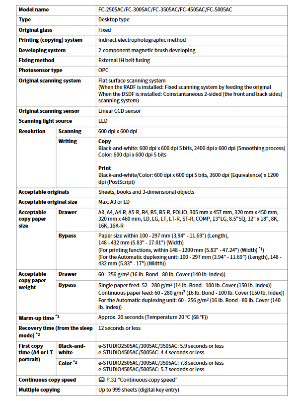
2.1 Paper adaptation specifications (universal core parameters for the entire series)

Specific parameter notes for adaptation dimensions

Size range standard sizes: A3/A4/A4-R/A5-R/B4/B5/LT/LD, etc

Non standard size: 100-297mm (length) × 148-1200mm (width) Printing support up to 1200mm

Media types: regular paper, recycled paper, thick paper (81-256g/m ²), ultra thick paper (257-300g/m ²), envelope, transparent film, waterproof paper, label paper. Envelopes do not support double-sided printing

Weight range: Paper box: 60-256g/m ²

Bypass paper feeding: 52-300g/m ², slightly different models

Recommended medium for regular paper: 80g/m ² (Toshiba TGIS/Mondi)

Thick paper: 90-120g/m ² (Color Copy series) requires the use of Toshiba recommended media to avoid malfunctions

2.2 Performance Core Parameters (Series Comparison)

Performance indicators e-STUDIO5005AC e-STUDIO5008A e-STUDIO7506AC e-STUDIO8508A

Continuous copying speed (A4/B&W) 20-50 pages/minute 20-50 pages/minute 55-75 pages/minute 55-85 pages/minute

Preheating time (20 ℃) 20 seconds 20 seconds 20 seconds 20-24 seconds

First copy time (A4) 4.4-9.5 seconds 3.6-4.3 seconds 4.1-6.4 seconds 4.1-5.2 seconds

Maximum continuous copy quantity 999 sheets 999 sheets 9999 sheets 9999 sheets

Maximum memory capacity of 1000 equivalent maximum 1000 equivalent maximum 1000 equivalent maximum 1000 equivalent maximum 1000 equivalent maximum 1000 equivalent

2.3 Resolution and Image Quality

Scanning resolution: 600dpi × 600dpi (fixed)

Printing resolution:

Black and White: 600dpi x 600dpi (5-digit), 2400dpi (equivalent) x 600dpi

Color: 600dpi x 600dpi (5-digit), 3600dpi (equivalent) x 1200dpi (PostScript)

Image processing: edge enhancement, smoothing, automatic density adjustment

3、 Optional accessories and extended functions

3.1 Four major categories of core accessories

Accessory category represents model core function adaptation series

Document input RADF (MR-3031) 100 page single and double-sided automatic feeding full series

DSDF (MR-4000) 300 pages high-speed double-sided scanning (120 pages/minute) 5005AC/5008A/8508A

Paper supply large capacity paper box (KD-1059) 2000 sheets A4/LT compatible with 5005AC/5008A

External large capacity feeder (MP-2502A/L) 2500 A4/LT compatible with 7506AC/8508A

Envelope drawer (MY-1049) for storing 60 envelopes in the entire series

Binding output ordinary stapler (MJ-1109) corner binding, sorting, grouping 5005AC/5008A

Horseback Nail Binding Machine (MJ-1112) Folding+Horseback Nail Binding (15 pages/set) 7506AC/8508A

Punching unit (MJ-6106) 2/3/4 hole punching (hole diameter 6.0-8.0mm) full series

System Extended Fax Unit (GD-1370) Super G3 Fax (33.6Kbps) Full Series

Wireless LAN Module (GN-4020) IEEE 802.11b/g/n+Bluetooth V3.0 Full Series

3.2 12 binding modes (core mode)

Binding Mode Function Description Required Accessories

Sort: Offset output in page number order using a regular stapler

Group by Set Offset Output Common Binding Tool

Staple Sort Single/Double Corner Binding (50 pages/set) Regular Binding Machine

Saddle Stitch Mid seam Folding+Binding (15 pages/set) Saddle Stitch Binding Machine

Center Fold Unbound Center Fold Horseback Nail Binding Device

Hole Punch 2/3/4 hole punching (adjustable spacing) punching unit

4、 Software and font support

4.1 Built in font library

PCL fonts: 79 types (including Courier, Arial, Times New Roman, etc.)

PS font: including Adobe standard fonts (Helvetica, Times, etc.)

Extended fonts: Supports Unicode font packs (optional)

4.2 Template and Storage

Template grouping: 1 public group+200 private groups

Number of templates per group: 60 per group

Storage method: HDD built-in storage (1GB fax memory)

5、 Environmental and safety regulations

5.1 Operating Environment

Temperature: 10-30 ℃ (normal use)

Humidity: 20-85% (no condensation)

Power supply: AC 120V/220-240V (± 10%), 50/60Hz

5.2 Safety and Compliance

Certification: CE/UL/CSA Security Certification

Protection: Overheating protection, overload protection, electrostatic protection

Disposal: Burning is prohibited and local environmental regulations must be followed

TOSHIBA V200 Series Programmable Logic Controllers

TOSHIBA V200 Series Programmable Logic Controllers
The Toshiba V200 series PLC is a general-purpose programmable logic controller based on Microsoft Windows system software configuration. Its core highlight is the full coverage of 132 ladder diagram instructions (including 8 categories such as I/O, data processing, logic operations, etc.), supporting bit/word/double word/floating point data operations, adapting to * * -32768 to 32767 (16 bits), -2147483648 to 2147483647 (32 bits) * * data ranges, with clock calendar settings, USB data log uploading, PID control and other extended functions. It follows strict safety regulations and is suitable for industrial automation control scenarios, providing complete installation, operation and maintenance guidance.
1、 Product basic information
1.1 Core positioning and applicable scenarios
Product Type: Universal Programmable Logic Controller (PLC)
Software dependency: Configuration software based on Microsoft Windows system
Applicable fields: Industrial automation control (such as motor control, process monitoring, etc.)
Core value: Flexible logic control, data processing, and system expansion achieved through 132 ladder diagram instructions
1.2 Safety and Environmental Regulations
Key requirements for standardized categories
Working environment temperature 0-50 ℃, humidity 5% -95% (no condensation), no corrosive gases
Installation requirements include independent metal conduit wiring, dedicated grounding wire (conduit grounding is prohibited), and non flammable insulated flooring
Operation qualification requires Qualified Person operation (with electrical equipment installation/maintenance skills and safety training)
The protection standards comply with NEC Article 110, OSHA, IEC 61131-2 and other standards
Modification restrictions prohibit unauthorized electrical/mechanical modifications (otherwise the warranty and safety certification will be invalidated)
2、 Detailed Explanation of Instruction System (8 Categories of Core Instructions)
2.1 Instruction Classification and Core Functions
Number of Instruction Categories Core Instruction Examples Applicable Scenarios
12 types of NO/NC contacts, rising/falling edge detection, pulse coil switch input/output control for I/O instructions
9 types of MOV (single/double word), block transfer, data exchange register, data move/copy instructions for data transfer
20 mathematical operation instructions for addition, subtraction, multiplication, and division (including floating-point), logarithmic and square root numerical calculations, and data conversion
Compare 16 types of instructions for greater than/less than/equal to/not equal to (supporting multiple data types) numerical condition judgment
16 types of logical instructions: AND/OR/XOR, shift/loop (1-bit/n-bit) bit logical operations, data shift
12 types of binary conversion instructions, ASCII/hexadecimal conversion, and data conversion in different formats
Timer/Counter Instructions: 5 types of ON/OFF timers, time control for increasing and decreasing counters, pulse counting
Program Control/Special Instruction 31: Subprogram Call, PID Control, Calendar Operation Program Flow Control, Extended Functionality
2.2 Key Instruction Characteristics
Data types supported: bit, word (16 bit), doublet (32-bit), floating-point (32-bit)
Accuracy: Floating point operations support a range of ± 3.4e ± 38, meeting high-precision control requirements
Highlights of extended instructions:
PID control: supports Pre proprietary Real PID1/PID4 algorithms, suitable for feedback control scenarios
Data log: USB upload CSV format file, supports date and time filtering, group storage
Calendar function: supports clock setting and time difference calculation (accurate to seconds)
Step sequence: STIZ/STIN/STOT instruction combination to achieve sequential operation control


3、 Hardware and System Configuration
3.1 Register and Device Resources
Register types: RAM registers (D/BW/SW, etc.), EEPROM hold registers (R)
Retention features: R register power-off retention, EEPROM write life of 10 million times, data retention of over 200 years
I/O Expansion: Supports local I/O and extended I/O modules, with Direct I/O instructions for real-time updates
3.2 System Function Support
Interrupt control: EI (enable)/DI (disable) instructions, supporting timer/IO interrupts
Watchdog timer: WDT command can extend scan timeout detection time (200ms base+1-100ms extension)
Error handling: Instruction Error Flag (ERF), overflow/underflow detection, data validity verification
4、 Key points of operation and maintenance
4.1 Installation and operation specifications
Before installation: Check the packaging integrity and model matching to avoid damaging the equipment during installation
Wiring requirements: Input power and control circuit are routed through separate conduits, and the return end of the control circuit is not grounded
Operation protection: Wear safety shoes, insulated gloves and other protective equipment, keep away from rotating machinery and live conductors
4.2 Maintenance and Disposal
Regular inspection: equipment status, label integrity, wiring tightness
Storage conditions: ventilated and dry environment, temperature 0-40 ℃, humidity 20% -80% (no condensation)
Disposal requirements: It is prohibited to burn electrical components and follow the disposal regulations of the local environmental protection department

TOSHIBA Unified Controller nv series™ Unified Controller nv series™

The Toshiba Unified Controller nv series type1 light controller is a second-generation V2000 CPU module, including three models: S (standard), H (high-performance), and D (redundant), using TC net ™ The high-speed serial I/O system (supporting 4km remote connection) is compatible with the IEC 61131-3 programming standard, with a program capacity of 32K-128K steps and a maximum of 192 I/O connections. It has the advantages of flexible expansion, high reliability, and V2000 S2 series program compatibility, and is widely used in industrial scenarios such as water, oil and gas, transportation, aviation, etc. It provides local/remote I/O control and redundant configuration options.

1、 Product basic information

1.1 Core positioning and advantages

Product Name: Toshiba Unified Controller nv Series Type1 Light Controller

Product positioning: Industrial grade sequential control module, second-generation V2000 CPU module, suitable for process control and discrete control scenarios

Core advantages:

Flexibility: Supports local/remote I/O configuration, TC-net ™  I/O system supports 4km long-distance connection

Reliability: Adopting high-quality IC and board level testing, D-type supports redundant configuration, automatic fault switching

Standardization: The programming software is compatible with the IEC 61131-3 standard and supports multilingual programming

Compatibility: Can directly replace V2000 S2 series, S2E/S2T series supports program migration

Work environment:

Working temperature: 0-55 ℃ (24-hour average ≤ 40 ℃)

Storage temperature: -40-70 ℃

Relative humidity: 5% -95% (no condensation)

Cooling method: natural cooling

1.2 Comparison of Core Parameters of Three Models

Model Program Capacity I/O Connections TC net Circuit Configuration Mode Core Features Order Number

Type1 light S (standard type) 32K steps, 32 points, no single machine compact type, supports G2 I/O, RS485+Ethernet interface HPUM11 * * S

Type1 light H (high-performance type) 64K steps, 64 points, 1 channel single machine built-in TC net master station, supporting G2/TC net I/O HPUM12 * * S

Type1 light D (redundant type) 128K steps, 192 points, 1-channel single/dual machine redundant master-slave automatic switching, compatible with key system HPUM14 * * S

2、 Core functions and performance

2.1 Hardware and Interface

Processor: 32-bit general-purpose processor+dedicated language processor (LP)

Communication interface

Standard configuration: Ethernet (100Mbps, up to 4 ports), USB (programming/monitoring)

S-type additional: RS485 (300bps-38.4Kbps)

Supporting network: TC net ™、 TOSLINE-S20, FL net, Profibus, etc

Execution speed:

Position operation: 0.04 μ s-0.08 μ s (contact), 0.08 μ s-0.16 μ s (coil)

Floating point operation: 0.2 μ s-0.4 μ s (multiplication)

Scanning cycle: 1-500ms (ultra high speed/high-speed scanning)

2.2 Programming and Software

Programming tool: nV Tool (supports Japanese/English/Chinese versions)

Supported languages: LD (ladder diagram), FBD (functional block diagram), SFC (sequential functional diagram), ST (structured text)

Software functions:

Custom graphic symbol editing, supporting device specific symbols

XML import/export, compatible with PLCopen XML Schema Ver.1.0

Debugging functions such as online monitoring, data tracking, and I/O forcing

Event logging (error logs, transmission logs)

​3、 System configuration plan

3.1 Local I/O Configuration

Architecture: 1 basic unit+up to 3 extension units

Number of slots: S/H-type 32 slots, D-type single machine 31 slots/dual machine 24 slots

Supporting modules: G2 I/O module (digital/analog/pulse)

Digital input: DC12-24V/AC100-240V, 8-64 points/module

Digital output: DC5-24V/AC100-240V, 8-64 points/module

Analog input: 1-5V/4-20mA, 4-8 channels, 8-16 bit resolution

Pulse input: up to 100kpps, 2 channels

3.2 Remote I/O configuration (supported by H/D type)

Core component: TC net ™  I/O adapter (SA912), I/O chassis (BU901/BU905), fiber optic cable

Performance parameters: 100Mbps transmission rate, up to 12 nodes, maximum distance 4km

Supporting modules: TC net I/O module (digital/analog/pulse)

Digital input: DC24V/48V, 32-64 points/module

Digital output: DC12-24V, 32-64 points/module

Analog input: 0-5V/0-20mA, 4-16 channels

3.3 Redundant configuration (only supported by D-type)

Architecture: Dual CPU modules+dual power modules, connected through redundant tracking cables

Switching mechanism: Automatically switches to slave CPU in case of main CPU failure, with no downtime

Applicable scenarios: Key systems such as dam control and oil and gas transportation

4、 Typical application scenarios

Application areas, specific scenarios, core functional system advantages

Water quality monitoring and wide area network interconnection of water supply and drainage control system, pump station linkage, flexible expansion

Oil and gas remote pump station control pump/motor monitoring, parameter configuration, fiber optic circuit redundancy, anti-interference

The brightness adjustment, ventilation control, and emergency equipment management of the traffic tunnel monitoring system are centrally monitored on a large scale for efficient operation

Airport ground lighting control, light switch/brightness adjustment, power maintenance, high-speed response, dual machine redundancy and reliability

Energy dam management system flood control, water level monitoring misoperation protection, stable operation

Material handling crane drive control motor control, status monitoring, flexible operation, long-term reliability

5、 List of Key Components

5.1 Core Hardware

Component type represents model and function description

Power module PS693 AC100-240V input, DC5.0V/7.0A output

IF661 G2 I/O Expansion Interface, Universal for Basic Unit/Expansion Unit

TC net adapter SA912 TC net I/O circuit to TC net I/O bus

Expansion cable CS6R5 standard expansion cable, length 0.5m

Redundant cable CX701 dual machine signal tracking cable, length 1m

5.2 Software Tools

Tool Name Version Type Function Description

NV Tool4 Japanese standalone version (HET81J4SS) integrated tool for programming, debugging, and monitoring

NV-Tool4 English Client Server Edition (HET82E4SS) Multi User Collaborative Programming

NV Tool4 Chinese standalone version (HET81C4SS) Chinese interface, suitable for domestic users

TOSHIBA PRODUCT GUIDE Discrete IGBTs

1、 Product basic characteristics
1.1 Core Definition and Advantages
Product positioning: Toshiba discrete IGBT is a power semiconductor that integrates the advantages of MOSFET and bipolar transistor, used in inverters and power conversion circuits
Core Features:
High input impedance, supports voltage driving, simplifies driving circuit
Fast switching characteristics, low carrier injection and recombination losses
The high current region still maintains a low collector emitter saturation voltage (VCE (sat))
Built in optimized diode for specific applications
Multiple packaging options, suitable for different installation scenarios
Structural principle: Adopting a pnpn four layer planar structure, conductivity modulation during conduction is achieved through pnp transistors to reduce saturation voltage
1.2 Key parameter range
Parameter Type Value Range Typical Values
Breakdown voltage (VCES) 200V-1500V 600V/900V/1200V (mainstream)
Collector current (IC) DC 8A-50A, pulse 20A-200A DC 30A-50A, pulse 100A-120A
Saturation voltage (VCE (sat)) 1.45V-2.3V 1.7V-2.1V (@ IC=30-50A)
Switching speed (tf) 0.05 μ s-0.3 μ s 0.1 μ s-0.2 μ s (@ VGE=15V)
Junction temperature (Tj) 150 ℃ -175 ℃ 150 ℃ (conventional), 175 ℃ (high-end model)
Package types TSON-8, SOP-8, TO-220SIS, TO-220SM, TO-3P (N), TO-3P (LH), etc-
2、 Product series and application scenarios
2.1 Four core application series
Series Name Core Characteristics Voltage/Current Range Typical Applications Representative Models
Universal inverter series hard switch, high rigidity, fast switch (fc up to 50kHz) 600V-1200V, IC 10A-50A Universal motor, inverter air conditioner, washing machine UPS GT30J121、GT50J102、GT25Q301
Soft switch series voltage/current resonance, low switching loss 600V-1500V, IC 15A-6A IH kitchen utensils, IH rice cookers, microwave ovens, multifunctional printers GT35MR21, GT50NR21, GT40T321
Flash series low gate drive voltage (2.5V-4.0V), ESD protection 400V, IC 130A-200A digital camera, DSLR camera GT8G151, GT10G131, GT5G133
Plasma display series high current conduction, low conduction loss 300V-600V, IC 200A plasma display panel (PDP) driver circuit GT30F124, GT45G127, GT30J124
2.2 Special advantages of soft switch series
Subdivision type: including 6.5 generation RC-IGBT (reverse conductive type), single-chip integrated freewheeling diode, no additional diode required, lower thermal resistance
Adaptation circuit: 100V-120V input adaptation voltage resonant circuit, 200V-240V input adaptation current resonant circuit
Key models: GT50MR21 (900V/50A), GT40QR21 (1200V/40A), with a junction temperature of 175 ℃, suitable for high temperature scenarios
2.3 Core Highlights of Flash Series
Gate driver: Supports low voltage driving from 2.5V to 4.0V, compatible with camera 3.3V/5V built-in power supply
Protection design: Built in Zener diode between gate and emitter, providing ESD surge protection
Packaging advantage: Adopting TSON-8/SOP-8 small packaging, suitable for compact space requirements of cameras


3、 Technological iteration and trends
3.1 Technical characteristics of each generation
Key features of voltage level generation core improvement
300V-400V 4-7 generation trench gate structure, wafer optimization, fine process low VCE (sat), high current, low driving voltage
600V 3-6 generation carrier injection optimization, thin wafer high rigidity, fast switching, soft switching adaptation
900V-1500V 4-6.5 generation trench gate, RC structure with low switching loss, high junction temperature, suitable for resonant circuits
3.2 Key Technology Improvement Direction
Wafer process: using thinner wafers and finer geometric patterns to reduce conduction losses
Carrier control: Optimize carrier injection and lifetime control, balance switching speed and saturation voltage
Reliability improvement: Some models have increased their junction temperature to 175 ℃, expanding their high-temperature application scenarios
Loss optimization: Compared to traditional MOSFETs, power loss is significantly reduced in high-frequency (20kHz-50kHz) scenarios
4、 Product Naming and Support
4.1 Model Naming Rules (Example: GT60M323)
GT: Toshiba discrete IGBT logo
60: Collector DC current (IC), unit A
M: Voltage level identification (M=900V, J=600V, Q=1200V, etc.)
3: Function series (3=Soft switch series)
23: Serial number, distinguishing specific feature versions
4.2 Support for discontinued products
Provide _final-phase and a list of obsolete products, including recommended alternative models (such as GT60M322 replacing GT60N321)
Alternative explanation: There may be differences in the characteristics of alternative models, and it needs to be confirmed that they are suitable for actual working conditions
4.3 Global Service Network
Overseas subsidiaries cover the United States, Brazil, Europe (Germany, France, etc.), Asia (Singapore, China, South Korea, etc.)
Service points in China: with offices in Beijing, Shanghai, Shenzhen, Chengdu and other locations, providing technical and sales support

Toshiba Integrated Control System V Series Selection Manual

The Toshiba V series integrated control system covers three models: Model 3000 (large), Model 2000 (medium/small), and Model 1000 (ultra small). It can be freely combined through sequential control (S module), loop control (L module), and computer control (C module), and is equipped with multi-layer networks such as Ethernet/TC net/DeviceNet. It supports 20000 tag points, 22 human-machine interface stations, and 32 control stations, and has advantages such as 40ns high-speed data processing and super PID algorithm. It is widely used in multiple industries such as petroleum, chemical, and power, providing high-performance and scalable distributed control solutions.

Core advantages

Hardware: Adopting the DCS template from Japanese company CONTEC, with high reliability; 40ns high-speed data processing

Software: Chinese character operation interface, suitable for domestic operators; Support simulation and remote management

Function: Super PID algorithm, suitable for high-precision control (boiler, combustion control, etc.); 100Mbps industrial control network

Applicable industries: petroleum, chemical, machinery, electricity, textile, metallurgy, pharmaceuticals, building materials, food, water treatment, environmental protection, etc

System architecture

2.1 Network Layering

Network hierarchy core role support type key parameters

Monitoring and management network connection monitors, operating devices, and V-series station Ethernet (single/dual network) support remote access and OPC data sharing

TC net supports 254 nodes for high-speed data transmission between control network stations, including TC net100 (100Mbps) and TOSLINE-S20/S20LP (2Mbps), with a transmission distance of 100m (cable)/2km (optical cable)

Fieldbus network connects field devices (sensors, drivers, etc.) such as DeviceNet and Profibus. The transmission rate of DeviceNet is 125kbps-500kbps, with a maximum of 64 points

2.2 Station Configuration Structure

Main Unit Configuration Bus Type I/O Expansion Capability Core Features

Model 3000 (large) 2-8 main slots+3-9 I/O slots Parallel bus (G3Bus), serial bus Each parallel bus extends 7 I/O units Support redundant configuration, suitable for large factory control

Model 2000 (medium/small) 1-5 main slots+3-8 I/O slots Parallel bus (G2Bus), serial bus Each serial bus connects 15 communication modules to balance expansion and cost, suitable for medium scale scenarios

Model 1000 (ultra small) integrated main module slot I/O bus (I/OBus) can connect up to 16 serial I/O modules. The structure is simple and suitable for small-scale control

Core hardware module

3.1 Main control module

Module type, core function, model adaptation, key specifications

S module (sequential control) high-speed sequential control, floating-point operation processing Model 2000/3000 Model 3000 maximum 112kstep program capacity, 40ns processing speed

L module (loop control) super PID algorithm, high-precision loop control. The entire Model 3000 supports 256 control loops, with a scanning rate of 32 loops/100ms

C module (computer control) Web/OPC server, data processing Model 2000/3000 with Windows system, maximum 512MB memory, 30GB hard drive

3.2 Communication module

Module Name Adaptation Network Model Adaptation Key Parameters

Ethernet module monitoring and management network supports 10BASE-T/100BASE-TX for all models, with a transmission rate of 10/100Mbps

TC net100 module control network Model 3000 dual network redundancy, scanning transmission capacity of 128kW/system

DeviceNet module fieldbus network model 2000/3000, with a maximum of 64 main stations, supporting interconnection of devices from multiple vendors

Profibus module fieldbus network model 2000/3000 transmission rate 9.6kbps-12Mbps, maximum 122 points for the main station

3.3 I/O module

Module type subdivision category key specifications (taking Model 3000 as an example)

Parallel I/O digital input (DI) DI335: 64 points, DC24V, 0.1A/point

Digital output (DO) DO333: 16 points, DC24V, 2.0A/point

Analog input (AI) AD368: 8 points, supports ± 10V/4-20mA, 12 bit resolution

Analog output (AO) DA374: 4 points, supports 4-20mA, 16 bit resolution

Serial I/O Analog Input (SAI) SAI06: 8 points, ± 10mV – ± 5V/4-20mA, 0.1% accuracy

Thermocouple input (STC) STC01: 8 points, supports J/K/T and other types, 0.2% accuracy

Digital Input (SDI) SDI01: 32 points, DC24V, 5mA, 10ms update cycle

Software system

4.1 Programming software

Software name, version type, core function

V-tool2/V-tool3 standalone/client/server version supports IEC61131-3 standard, including configuration editing, symbol assignment, and online debugging

Tag editor integrated tool for managing loop control tag database, including tag signatures, PID parameters, etc

System log auxiliary tool displays error logs, event logs, and I/O error information

4.2 Human Computer Interface Software

Software type represents the key specifications of the product

The OIS-DS large-scale system supports 20000 tag points, 22 human-machine interface stations, and 32 control stations

The OIS-DS SMART small system supports 4000 tag points, 8 human-machine interface stations, and 8 control stations

Core functions – real-time data display, trend monitoring, alarm management, remote access, redundant backup

Core differences among the three models

Comparison Dimension Model 3000 (Large) Model 2000 (Medium/Small) Model 1000 (Ultra Small)

Applicable scenarios: DCS control for large factories, medium/small-scale process control, single point control for small equipment

Maximum program capacity: 112kstep, 64kstep, 6kstep

256 control circuits, maximum 96, 8/500ms

The network supports Ethernet/TC net and other (redundant) Ethernet/TOSLINE and other Ethernet/TOSLINE-S20LP

Main module configuration S/L/C module fully supports S/L/C module only supports L module

Tag points support 20000, 8000, and 4000

TOSBERT VF-AS3 Industrial Inverter Quick Start Manual

1. Basic information

Product positioning: Used for controlling the speed of three-phase induction motors, built-in permanent magnet synchronous motors (IPMSM), and surface permanent magnet synchronous motors (SPMSM) in industrial scenarios, and cannot drive single-phase motors

Voltage and power range:

500V level: 1.5kW-55kW

600V (575V) level: 2HP-75HP (HD)/3HP-100HP (ND)

690V level: 2.2kW-75kW (HD)/3kW-90kW (ND)

Core features: Supports multiple ratings (HD/ND), V/f control, vector control, PID control, built-in EMC filter and DC reactor

2. Core security standards

2.1 Personnel and Protection Requirements

Qualification requirements for homework types require necessary protective equipment

All qualified installation/maintenance personnel shall wear protective gloves and safety work clothes

Electrical work requires the qualification of insulated gloves, insulated shoes, and anti electric shock clothing

High altitude operations (≥ 50cm) require industrial safety helmets with high-altitude operation qualifications and ladders that comply with ISO14122 standards

Shoes for heavy object transportation (≥ 20kg) without special qualifications but requiring training on anti smashing toe caps

Qualified maintenance personnel with electrician specific protective gloves for maintenance operations

2.2 Key safety taboos

High voltage operation: After power failure, wait for 15 minutes (capacitor discharge), confirm that the charging light is off and the DC voltage is ≤ 45V before operation

Prohibited behavior:

Do not disassemble the front cover/small front cover (including high-voltage components inside) while it is live

Do not connect the power supply to the output terminals [U/T1] [V/T2] [W/T3]

Do not modify equipment or use non specified accessories

Prohibit the use of welding machines in enclosed spaces (to prevent carbon monoxide poisoning)

Power requirement: Do not connect the corner grounding system, IT system needs to disconnect the grounding capacitor

​3. Installation and wiring

3.1 Installation environment and conditions

Remarks on the Range of Environmental Parameter Requirements

If the ambient temperature is between -15 ℃ and+60 ℃ and exceeds 50 ℃, it is necessary to reduce the capacity for operation

Relative humidity 5%~95%, no condensation

Altitude ≤ 2000m>1000m, capacity reduction of 1% per 100m

Vibration ≤ 5.9m/s ² (10-55Hz) Avoid installation in locations with high vibration

Installation location: Indoor, no direct sunlight, no corrosive gas/oil mist, ventilation space needs to be reserved

3.2 Installation and wiring specifications

Installation method:

Wall mounted installation: NEMA Type 1 kit is required (NEM301Z for A1Y, NEM302Z for A2Y)

Multiple parallel devices: A1Y spacing ≥ 11mm, A2Y spacing ≥ 11mm, with a ventilation space of ≥ 10cm reserved above and below

Wiring requirements:

Power terminal: [R/L1] [S/L2] [T/L3] (three-phase input)

Motor terminals: [U/T1] [V/T2] [W/T3] (three-phase output)

Grounding terminal: [PE], wire diameter needs to be matched (such as 600V HD type 12AWG corresponding to grounding 12AWG)

Terminal torque: A1Y 12AWG is 26.5lb · in, A2Y output terminal is 363lb · in

4. Parameter settings

4.1 Core Parameters (Basic Settings)

Parameter Name Function Adjustment Range Default Settings

CMOd (Command Selection) Select the control mode terminal/operation panel/communication, etc. 0 (terminal)

FMOd (frequency command selection) Select frequency control source terminal/touch screen/communication, etc. 1 (terminal RR)

ACC (Acceleration Time 1) Acceleration Time from 0Hz to FH 0.0~6000s 10.0s

Deceleration time from FH to 0Hz for dEC (deceleration time 1) is 0.0~6000s 10.0s

FH (maximum frequency) output frequency upper limit 30.0~590.0Hz 80.0Hz

AUL (Multiple Rating Selection): Select HD/ND and voltage levels 2 (ND-600V), 3 (HD-600V), etc. 3 (HD-600V -60Hz)

4.2 Differences in Multiple Rated Values (HD/ND)

Rated Value Type Overload Capacity Applicable Scenario Parameter Setting (AUL)

HD (Heavy Duty) 150% -60s constant torque load (conveyor, crane, etc.) 3 (600V), 15 (500V), 17 (690V)

ND (Normal Duty) 120% -60s variable torque load (fan, pump, blower, etc.) 2 (600V), 14 (500V), 16 (690V)

5. Standard compliance measures

5.1 Main Compliance Standards

Key measures for compliance requirements of standard types

The EMC directive complies with IEC61800-3, CISPR11 with built-in EMC filters, shielded cables, and separate wiring

Low voltage instructions comply with IEC61800-5-1 for installation in cabinets, standardized grounding, and installation of protective devices

UL/CSA standards comply with UL61800-5-1, using UL certified cables and installing specified fuses/circuit breakers

ATEX directive not applied for and cannot be used in explosion-proof scenarios

5.2 Short circuit protection configuration (UL/CSA standard)

Inverter Model Maximum Voltage (V) Branch Circuit Protection (Fuse) Power Wire Specification (AWG) Grounding Wire Specification (AWG)

VFAS3-6022PC 600 Class J,10A 12 12

VFAS3-6110PC 600 Class J,25A 10 10

VFAS3-6300PC 600 Class J,60A 4 2

VFAS3-6750PC 600 Class J,150A 1/0 2

6. Product specifications and warranty

6.1 Core specifications (taking 600V HD type as an example)

Model Applicable Motor (HP) Output Capacity (kVA) Output Current (A) Cooling Method Weight (kg)

VFAS3-6022PC 2 3.1 3.1 Forced Air Cooling 21.6

VFAS3-6110PC 10 13 13.5 Forced Air Cooling 21.6

VFAS3-6300PC 30 34 34 forced air cooling 51.9

VFAS3-6750PC 75 83 83 Forced air cooling 52.5

TOSHIBA VRF Dx coil interface device Service Manual

1. Basic information

Core equipment:

Dx coil controller: TCB-IFDMX01UP-E (without relay terminal block), TCB-IFDMR01UP-E (with relay terminal block)

Dx valve kit: RBM-A101UPVA-E (diameter Ø 12.7mm), RBM-A201UPVA-E (diameter Ø 15.88mm)

Applicable system: Can connect SMMS-u/∞/e/7 and SHRM-e series VRF outdoor units, requiring on-site preparation of AHU and DX COIL (direct expansion coil)

2. Core technical parameters and configuration

2.1 System Types and Functions

System type Core function Temperature setting range (℃) Adaptation scenario

TA type remote control set return air temperature control for cooling 13-25/heating 18-30 room temperature adjustment

TF type remote control set air supply temperature control 18-29 ventilation system

DDC type 0-10V analog direct capacity control without room temperature control function AHU system linkage supply air temperature control

2.2 Key Hardware Parameters

Refrigerant: Only R410A is supported, and it is prohibited to mix with other refrigerants such as R22. Ventilation is required after leakage (toxic gases are generated in case of fire)

Sensor:

Core sensors: TC1 (gas side), TC2 (liquid side), TCJ (capillary), TA (return air), TF (supply air)

Resistance characteristics: TC2/TCJ resistance is 10.0k Ω at 25 ℃, TA/TF sensor resistance is 12.6k Ω at 25 ℃

Installation requirements: TC1/TC2/TCJ need to be fixed by brazing, with a distance of 50 ± 25mm from the end plate

Pipeline restrictions:

Valve kit to DX COIL maximum actual length: 5m

Total piping length: TA type 200m, TF/DCD type 120m (100m in parentheses)

Maximum height difference: 40m between outdoor unit and indoor unit

2.3 Capacity Adaptation Table (Partial Core Specifications)

DX COIL type controller model, valve kit model, compatible capacity (HP)

Ordinary TCB-IFDMX01UP-E RBM-A101UPVA-E 8-40

Ordinary TCB-IFDMX01UP-E RBM-A201UPVA-E 14-40

Interlocking/facet type TCB-IFDMX01UP-E RBM-A101UPVA-E 42-120

3. Operation and safety regulations

3.1 Personnel Qualification Requirements

Qualified installation personnel: must receive Toshiba Carrier training and possess relevant qualifications for electrical operations, refrigerant operations, high-altitude operations, etc. (in compliance with local regulations)

Qualified maintenance personnel: In addition to the qualifications of installation personnel, they also possess equipment maintenance skills

3.2 Safety Protection Requirements

Required protective equipment for homework types

All homework protective gloves and safety work clothes

Electrical related insulated gloves, insulated shoes, and anti electric shock clothing

Industrial safety helmets for high-altitude operations (≥ 50cm) and ladders that comply with ISO14122 standards

Shoes with anti smashing toe caps for heavy transportation

Electrician specific protective gloves for maintenance operations

3.3 Key operation taboos

Power off requirements: The circuit breaker must be turned off before operation, and a 5-minute wait (capacitor discharge) is required before opening the electrical box cover

Refrigerant operation: It is prohibited to directly recycle it to the outdoor unit, and specialized equipment is required for recycling; Thoroughly empty the air before filling

Modification prohibition: Equipment or parts must not be modified, and replacement parts must comply with the manual specifications (such as relay G2RV-SR700-12DC)

Installation restriction: Indoor unit installation height ≥ 2.5m, prohibited from installation in areas prone to combustible gas leakage

4. Control Logic and Input/Output

4.1 Core Control Functions

Automatic capacity control: TA type is based on the difference between the return air temperature and the set value, while TF type is based on the difference between the supply air temperature and the set value, as well as the temperature change

Protection function:

Anti cold air emission: Control fan speed based on sensor temperature during heating

Anti freezing control: detect the temperature of the coil during cooling to avoid freezing

Oil recovery control: Regularly recover compressor lubricating oil during cooling/heating

Mandatory function: TF type supports forced constant temperature shutdown (such as fan forced shutdown when TA ≤ 5 ℃)

4.2 Input/output ports (MCC-1777 circuit board)

Analog input: 0-10V (AI1-AI4), 4-20mA (AI1-AI2)

Analog output: 0-10V (AO1-AO2), fan speed output (HH=9V, H=6V, L=2V)

Digital inputs: safety contacts, external fault inputs, operation mode selection (DI1-DI6)

Digital output: operating status, alarm, fan speed, defrost mode (DO1-DOE)

Communication interface: Modbus (supports RS-485, baud rate optional 9600-57600bps)

5. Troubleshooting and maintenance

5.1 Common check codes and their meanings

Inspection code fault type troubleshooting direction

P05 Power supply phase loss/wiring error check power supply wiring and circuit breaker

P10 safety contact disconnection inspection DI1 terminal connection

L30 external fault input check AHU fan operation status

F10 TCJ sensor fault check whether the sensor wiring is short circuited/open circuited

5.2 Maintenance points

Insulation test: After the operation, a 500V megohmmeter should be used to test, and the resistance between the live part and the non live metal should be ≥ 1M Ω

Leak detection requirement: refrigerant leakage must be checked after installation/maintenance

Test Run: Need to enter TEST mode through wired remote control, only supports cooling/heating mode testing

Parts replacement: The controller core circuit board is MCC-1777, and the sensor cable length is 7.5m. If it is insufficient, the optional sensor TCB-IFDES1001P-E (10m) is needed

6. Key settings and calibration

System type setting: configured through SW501 switch (TA type fully closed, TF type only Bit2 on, DDC type Bit3 on)

DN code setting: It needs to be configured with a wired remote control (RBC-ASCU1-E), including device capacity, valve kit type, sensor function, etc. (such as DN11 setting capacity code, DN4AE setting valve kit type)

Modbus settings: configured through SW506 (baud rate) and SW507 (address), supporting up to 16 devices for networking

Toshiba TE3 Series Low Voltage Digital Solid State Soft Starter User Manual

The Toshiba TE3 series is a low-voltage digital solid-state soft starter with a current range of 18-1250A, supporting 208-600VAC three-phase power supply. It has core functions such as soft start/soft stop, current limitation, overload protection, etc. It integrates 5 digital outputs, 4 digital inputs, and 1 analog input/output, supports Modbus RTU communication and local touch screen operation, and can quickly adapt to more than 30 application scenarios such as mixers and compressors through Auto Setup. It has multiple protections such as over temperature, phase loss, thyristor fault, etc. The installation needs to comply with NEC standards and is suitable for smooth starting and protection of industrial rotating machinery, reducing starting surge current.

1、 Product infrastructure and specifications

1. Summary of core specifications

Project specification details

Current range: 18A (TE3-18) -1250A (TE3-1250), a total of 12 models

Voltage range: 208VAC, 240VAC, 480VAC, 600VAC, three-phase

Power adaptation for 208VAC: 5-450HP; 600VAC:10-1200HP

Start time 1-300s (customizable)

Soft stop time 0-300s (customizable)

Overload level 10/20/30 (corresponding to different trip curves)

Communication parameters Modbus RTU (addresses 1-32, baud rates 9600-11520)

Weight range 4kg (TE3-18) -181kg (TE3-1250)

2. Input/output interface

Interface type specification parameters

Digital input (DI) 4-channel, supports 110/230VAC or 24VDC, can map start/stop/reset and other functions

Digital output (DO) 5 channels, 240VAC 1A (DO1-DO4), 240VAC 3A (DO5), supporting fault/operating status output

Analog input (AI) 1 channel, 0-10V or 4-20mA, can map current limit, overload and other functions

Analog output (AO) 1 channel, 0-10V or 4-20mA, can output measured current and overload percentage

Special interface PTC thermistor input (PTC+/PTC -), supporting motor temperature protection

2、 Core functions and configurations

1. Start and stop function

Soft start: By controlling the voltage ramp (1-300s), the starting shock is reduced, and the starting base voltage can be adjusted by 10% -100%.

Kick Start: For viscous loads, provide 10-2000ms torque pulses (30% -80% voltage) to assist in starting.

Current limit start: Limit the starting current to 50% -600% of the motor FLA to avoid grid impact, with a limit time of 1-600s.

Soft stop: voltage ramp deceleration (0-300s), supports automatic smooth stop, and prevents water hammer effect on pump equipment.

2. Automatic configuration and application adaptation

Auto Setup: Built in 30+preset application scenarios (such as centrifugal compressors, screw conveyors, submersible pumps, etc.), one click matching of startup parameters.

Parameter adaptation: Automatically adjust the starting base voltage, ramp rate, current limit and other parameters to adapt to different load characteristics.

Quick debugging: Supports parameter backup to USB, batch copying of configurations, firmware can be upgraded through USB.

3. Detailed explanation of protection functions

Protection type triggering condition response method

When the overload protection current exceeds 115% of the motor FLA and reaches the corresponding overload level, the trip time will trip and the machine will stop. Manual/automatic reset is required

Over temperature protection: The radiator trips and stops when the temperature exceeds 90 ℃, and automatically resets after cooling

Phase loss protection: If any phase is missing on the input/output side, it will trip immediately

Low current protection motor current<25% motor FLA, continuous 4000ms (customizable) trip shutdown

Thyristor malfunction: The thyristor is not conducting properly/short circuited and immediately trips. It is necessary to check the resistance of L1-T1/L2-T2/L3-T3

PTC protection PTC thermistor resistance>4k Ω or open circuit tripping shutdown

Voltage imbalance, three-phase voltage difference exceeding allowable range, tripping and shutdown

4. Energy saving and monitoring functions

IERS intelligent energy-saving: dynamically adjust the motor voltage to reduce energy consumption under light load, with an adjustable energy-saving level of 0% -100%.

Real time monitoring: The touch screen displays parameters such as three-phase current, voltage, power factor, radiator temperature, overload percentage, etc.

Log recording: Stores historical data of 10 trip events, peak current at start/stop, and radiator temperature, supports USB export.

Automatic reset: Supports 0-7200s reset delay, 0-10 retries, and can choose to automatically reset for faults such as phase loss and overload.

3、 Installation and compliance requirements

1. Installation specifications

Installation method: Vertically installed on a flat surface, with reserved ventilation gap (minimum 25mm, 127-483mm for high current models).

Environmental requirements: Avoid dust, corrosive gases, and severe vibrations. When the altitude is greater than 1000m, reduce the capacity by 1% for every 100m increase (up to 2000m).

Wiring requirements: The main circuit uses copper conductors with a wire diameter of 0.3-1010mm ² and a wiring torque of 2.8-124.3N · m. The control circuit and the main circuit are wired separately and shielded wires are used.

Short circuit protection: Class J/L/RK5 fuses or circuit breakers with rated currents of 100A-1600A (depending on the model) are required.

2. Compliance standards

Electrical safety: Complies with NEC 70 (NFPA 70), UL508, and cUL508 standards.

Electromagnetic compatibility: EN 55011 Class A, IEC 61000-4 anti-interference standard.

Environmental compliance: RoHS compatible, waste must comply with local electronic waste disposal regulations.

4、 Operation and maintenance

1. Control method

Local control: Supports multi language switching through touch screen start stop, parameter configuration, and status viewing.

Remote control: Two wire/three wire control (DI interface), Modbus RTU communication (supports start/stop, parameter read/write).

Manual/Automatic Switching: Supports Hand/Auto mode, automatically switches to local control in case of communication failure.

2. Maintenance points

Regular inspection: Clean the radiator at least once a year, check the tightness of the wiring, and verify the protective function.

Troubleshooting: Quickly locate the problem (such as 101=input side L1 phase loss) through the trip code (101-2799).

Long term storage: ambient temperature -25 ℃~70 ℃, dry and ventilated, avoid stacking and heavy pressure.

Toshiba T1-16S Programmable Controller I/O Module

Toshiba T1-16S is a programmable controller that supports multi module expansion. The core supports up to 8 I/O module extensions (including 11 types such as digital, analog, thermocouple, network module, etc.). The single module I/O points cover 8-16 points, and the analog module resolution reaches 12 bits. It supports 24Vdc digital input/output, 0-5V/0-20mA/± 10V analog signal, and K/J/E thermocouple input. Network communication can be achieved through TOSLINE-F10 or DeviceNet. The I/O register adopts continuous address allocation and supports automatic/manual configuration. The module needs to be installed in a power-off state, suitable for industrial automation control scenarios.

Product Infrastructure

1. System composition and scalability

Core component specification details

Main controller T1-16S main unit, built-in X+Y 4W I/O type (XW00, XW01, YW02, YW03 registers)

The expansion module supports up to 8 module stacks, with expansion on the right side and module connections through expansion connectors

11 types of modules (4 digital quantities, 4 analog quantities, 1 thermocouple, 2 network modules)

Maximum I/O points of 144 (fully configured with 8 16 point modules)

The main power supply unit provides 5VDC power supply, with a module power consumption of 50-400mA/module (RO108M maximum 260mA, TC111M maximum 400mA)

2. Summary of core module specifications

Module model type key parameter register allocation

DI116M 16 point DC input 24Vdc, 5mA/point, ON delay 10ms X 1W (1 input register XW)

DO116M 16 point DC output 5-24Vdc, 100mA/point, voltage drop ≤ 0.4V Y 1W (1 output register YW)

DD116M 8-in-8-out combination input 24Vdc/5mA, output 24Vdc/100mA X+Y 2W (1X+1Y register)

RO108M 8-point relay output 240Vac/24Vdc, 1A/point, mechanical life 20 million times Y 1W (1 output register YW)

AD121M 1-channel analog input 0-5V/0-20mA, 12 bit resolution, accuracy ± 0.5% FS X 1W (1 input register XW)

AD131M 1-channel analog input ± 10V, 12 bit resolution, input impedance ≥ 1M Ω X 1W (1 input register XW)

DA121M 1-channel analog output 0-20mA, 12 bit resolution, load ≤ 600 Ω Y 1W (1 output register YW)

DA131M 1-channel analog output ± 10V, 12 bit resolution, output impedance ≥ 10k Ω Y 1W (1 output register YW)

TC111M 1-channel thermocouple input K/J/E type, -200~1200 ℃, resolution 0.3-0.63 ℃ X 1W (1 input register XW)

FR112M TOSLINE-F10 remote station 750/250kbps, transmission distance 500m/1km TL-F (SW34/SW35 special registers)

DN111M DeviceNet slave station 125/250/500kbps, 4-16 word I/O data OPT (RW240-RW255, D4000-D4095)

Core functions and technical features

1. Signal processing capability

Digital module: Input supports 24Vdc (± 10/-15%), output supports 5-24Vdc, relay module supports 240Vac/24Vdc load, single channel maximum 1A.

Analog module: 12 bit resolution (1/4000), conversion cycle 2ms, accuracy ± 0.5% FS (25 ℃), ± 1% FS (0-55 ℃), input/output range covering 0-5V, 0-20mA, ± 10V.

Thermocouple module: supports K (-200~1200 ℃), J (-200~800 ℃), E (-200~600 ℃) types, input impedance ≥ 1M Ω, conversion period ≤ 20ms.

Anti interference design: The digital quantity can withstand a voltage of 1500Vac (1 minute), and the analog quantity is isolated by optocouplers. It is recommended to use shielded twisted pair wiring.

2. Communication and network functions

Core characteristics of network module communication parameters

FR112M (TOSLINE-F10) transmission speed of 750/250kbps, bus topology at a distance of 500m/1km, 1-letter receiving/1-letter sending, station address 0-30

DN111M (DeviceNet) transmission speed of 125/250/500kbps, node address 0-63 at a distance of 100m, 4-16 word I/O optional, supporting Polling mode

3. I/O configuration and register allocation

Configuration method:

Automatic configuration: By executing commands through the programmer, the main unit automatically detects hardware and generates a configuration table.

Manual configuration: Set the I/O type (X/Y/X+Y/TL-F/OPT) slot by slot, supporting 1-16 word register allocation.

Register rules:

Continuous address allocation for input register (XW) and output register (YW), with the first half of the X+Y type being XW and the second half being YW.

Special modules: FR112M occupies SW34/SW35, DN111M occupies RW240-RW255 (status/request), D4000-D4095 (I/O data).

Status display: The I/O status of each module can be switched and displayed through the main unit LED, which can be configured through the special register SW54 (0=main unit, 1-8=module slot).

Installation and safety regulations

1. Installation requirements

Module installation: It must be powered off and stacked from the right side of the main unit. Unused expansion connectors need to be covered with dust covers.

Wiring specifications: The digital module uses a 24 pin connector (optional welding type/flat cable type), the relay module uses M2 screw terminals (wire diameter 0.3-1.25mm ²), and the analog/thermocouple uses shielded twisted pair.

Environmental adaptation: The working temperature is 0-55 ℃, and the digital input capacity decreases with the ambient temperature (the number of ON points is halved at 60 ℃).

2. Safety regulations

Electrical safety: The module has a withstand voltage of 1500Vac (digital)/500Vac (analog) and an insulation resistance of ≥ 10M Ω.

Operation taboos: Do not touch electronic components on printed circuit boards, do not plug or unplug modules with power on to avoid the risk of short circuits.

CE certification: The DeviceNet module needs to be equipped with a ferrite core (within 10cm of the cable) and a shielding layer grounded (≤ 100 Ω) to meet the EMC directive.

Malfunctions and Maintenance

Fault indication: DN111M displays status through dual color LED (green=normal communication, red=fault, orange=power on self-test).

Error handling: When there is a network communication failure, FR112M triggers S00D special relay, while DN111M maintains the previous data.

Module replacement: Supports individual module replacement, and after replacement, it is necessary to ensure that the I/O configuration table is consistent with the hardware.

Vibro Meter CE 680 M511 piezoelectric accelerometer

Product basic information

Project Details

Product Name: Piezoelectric Accelerator with Integrated Electronics

Model and specification CE 680 M511

Order number 444-680-000-511

Brand affiliation Vibro Meter SA (Meggitt Group)

Core positioning: Industrial machinery vibration monitoring, suitable for harsh environments

Core performance parameters

1. Electrical performance

Parameter specification values

Sensitivity (+25 ° C) 100 mV/g ± 5%

Dynamic range 80 g

Lateral sensitivity (maximum) 5% in the axial direction

Linearity within the full range ≤ 1%

Supply voltage 18-30 VDC

Input power supply current 2-10 mA (constant current)

Output impedance (maximum) 100 Ω

Bias output voltage (broadband) 12 VDC

Electrical noise (equivalent g) spectral density: 5 μ g/√ Hz at 10 Hz; 5 μ g/√ Hz at 100 Hz/1000 Hz

Protection function: reverse polarity protection, ESD protection

2. Frequency and temperature characteristics

Characteristic specification details

Frequency response -3 Hz-5 kHz: ± 5%

– 1 Hz-9 kHz:±10%

– 0.5 Hz-14 kHz:-3 dB

Resonance frequency 30 kHz

Working temperature range -55 ° C to+120 ° C

Temperature response deviation within the range of -55 ° C to+120 ° C ± 5% (typical value)

3. Environmental and mechanical characteristics

Characteristic specification values

Vibration limit (peak) 500 g

Impact limit (peak) 5000 g

Base strain sensitivity (maximum) 0.0002 g peak/μ ε

Electromagnetic sensitivity (equivalent) 70 μ g/Gauss

Hermetically sealed

Shell material 316L stainless steel

Weight 90 grams

Sensor element design PZT ceramic/shear mode

Installation and Accessories

1. Installation specifications

Installation method: 1/4-28 UNF threaded hole (2B grade)

Installation torque: 3 Nm

Output connector: 2-pin MIL-C-5015 standard interface

Compatible connector: MS3106F-10SL-4S or equivalent model

2. Accessory configuration

Type Name Specification Part Number

Standard adapter screw 1/4-28 UNF-

Optional cable EC 318 922-318-000-xxx

Optional cable EC 319 922-319-000-xxx

Optional installation adapter MA 122_012 809-122-000-012

Optional insulation stud MA 122_021 809-122-000-021

Core advantages and usage instructions

Anti interference design: shell insulation+internal shielding, avoiding interference from grounding loops and frame voltage on measurement, suitable for complex industrial environments.

Stability performance: Excellent bias voltage stability under high temperature, low noise level, ensuring measurement accuracy.

Calibration feature: Dynamic calibration is completed at the factory, and no additional calibration is required for subsequent use, reducing maintenance costs.

Applicable scenarios: Suitable for industrial machinery vibration monitoring, especially for equipment status monitoring in harsh environments.

Search for products

Back to Top
Product has been added to your cart