Call us 24/7uaedcs@163.com
Welcome to the official website of CNIACS Automation Technology Co., Ltd!
Call us 24/7uaedcs@163.com

Eaton XVH300 MICRO PANEL

Basic Information

Document information: Released in November 2014, replacing version M001506. The German version is the original description, and other language versions are translated versions. The copyright belongs to Eaton Automation Co., Ltd. Reproduction and dissemination are prohibited without permission.

Equipment Overview

Name: XVH300 and MH2 are different names for the same product.

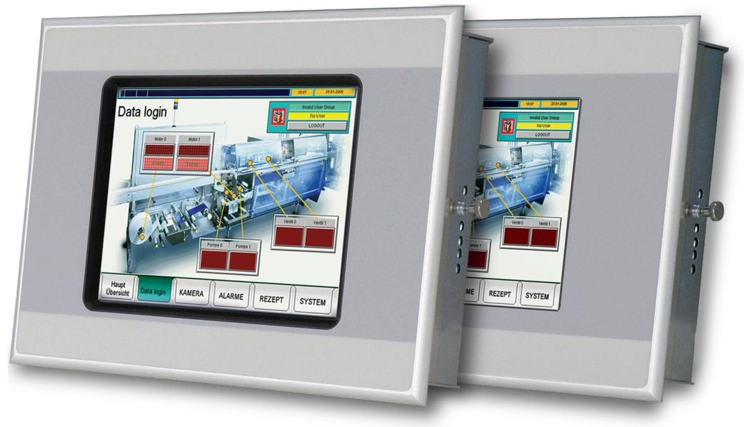
Function: As an HMI device, it is mainly used in mechanical and system manufacturing, specifically for visualization and operation of machines and systems. Other uses require prior consultation with the manufacturer.

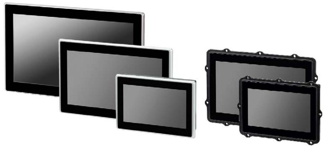
Version: Divided into multiple versions based on touch type (resistive, infrared) and interface (no fieldbus, CAN, Profibus, Suconet K, RS232, etc.), such as XVH-330-57BAS, XVH-340-57CAN, etc.

Packaging content: Includes MICRO PANEL host, fixed bracket with threaded pins for installing equipment, installation sealing strip, power connector, etc., and accessories such as handwriting pens can also be ordered.

Safety regulations

Symbol meaning: Different symbols are used according to the degree of danger, such as “DANGER” indicating extreme danger that may result in death or serious injury; Warning “indicates potential danger that may result in death or serious injury.

Personnel requirements: Installation, operation, maintenance, and service personnel must have sufficient qualifications, undergo training, and understand the hazards and risks related to the equipment.

Prohibited use: The use of this device for safety purposes (related to personnel and machine protection) is prohibited.

Equipment related hazards and prevention

There is a risk of explosion, and specific requirements must be followed when operating in potentially explosive environments, such as avoiding dangerous impacts, disconnecting plug connections after power failure, etc.

There are live parts inside the equipment. It is forbidden to open the equipment to prevent electric shock.

The protective grounding system between different devices may generate large balanced currents, and equipotential bonding conductors need to be installed if necessary.

Static discharge may damage electronic components, so it is necessary to release body static electricity before coming into contact with the equipment.

Resistive touch surfaces are sensitive, avoid touching with sharp objects, and ensure gloves are clean when operating.

Operation and indication components

Front: There is a touch sensor (detecting the triggering of operating elements on the display screen) and a display screen (displaying operating and indicating elements).

Service side: There are operating components such as CF card slot cover, CF slot, eject button, control button, as well as indicator components such as CF ACT, CAN ACT/PROFIBUS ACT. Different indicator lights have different meanings, such as CF ACT light on indicating that the CF card is being accessed.

On the connector side of the SKS device, there are indicator lights such as “COM PORT ERROR” and “COM PORT ACT”, as well as a “LINE TERM. COM PORT” switch, which are used to indicate data transmission errors, data transmission activity, and control the terminal resistance of the RS485 interface.

Installation

Installation location requirements: It needs to be installed in an approved location, and the power supply must meet the requirements. Considering the engineering acceptance conditions of UL certification, the installation location should avoid direct sunlight, ensure that the operating components and cable connections on the service side of the equipment are accessible, meet environmental conditions and ventilation requirements, and the installation surface must meet specific thickness, flatness, and roughness requirements.

Interface: Different versions of devices have different interfaces, including Ethernet, CAN, Profibus, RS232, RS485, USB device interfaces, power interfaces, etc. Each interface has corresponding wiring requirements and specifications.

Installation steps: Check for equipment transportation damage, prepare installation cuts in control cabinets and other locations, install sealing strips, place the equipment into the installation cut from the front, fix it with fixed brackets, etc. Pay attention to relevant safety regulations during installation.

Operation

Safety regulations: Before operation, it is necessary to read the safety regulations section and pay attention to protecting the resistive touch surface to avoid turning on the device when condensation occurs due to climate change.

Start the device: Insert a CF card with an operating system, turn on the power, and the device will start. After initial debugging, adjust the system settings and install the required applications.

Turn off the device: Disconnect the power of the device. Before turning off, make sure that no software is writing to the CF card to avoid frequent device switching to extend the backlight life.

Maintenance and Service

Safety regulations: Before maintenance, it is necessary to read the safety regulations chapter.

Maintenance work: Resistive touch devices are basically maintenance free, and can be cleaned or recalibrated if necessary; Infrared touch devices require regular cleaning of the infrared frame and do not require recalibration.

Battery: The built-in battery is non replaceable and has a certain lifespan.

Maintenance: The equipment can only be opened by the manufacturer or authorized maintenance center. Maintenance requires contacting the local supplier or Eaton technical support. Transport equipment must be in its original packaging.

Troubleshooting: Listed the reasons and solutions for common faults such as device failure to start, error messages during startup, screen dimming, and unresponsive touch.

Storage, transportation, and disposal

Storage: Must meet environmental conditions requirements.

Transportation: During transportation, it is necessary to prevent equipment damage and meet environmental conditions. After arrival, inspect the equipment for transportation damage.

Disposal: The equipment contains explosive and toxic materials such as lithium batteries and cold cathode tubes, which need to be properly disposed of or returned to the manufacturer in accordance with national regulations. The materials used for the equipment and packaging should be explained.

Eaton XV-303/XV-313 multi touch display

Basic Information

Document information: Released in March 2025, version 01.1, copyright belongs to Eaton Corporation. Reproduction, dissemination, etc. are not allowed without permission.

Equipment Overview

Function: It can be used as an operation and monitoring device, or as an operation and control device with PLC function. It adopts industrial high-resolution capacitive multi touch technology, has an intuitive gesture based user interface, and a powerful graphics processing unit.

Model difference: XV-303 is a front mounted type, while XV-313 is a rear (panel) mounted type.

Display size: There are three widescreen sizes: 7.0 inches, 10.1 inches, and 15.6 inches, with resolutions of 1024×600 pixels and 1366×768 pixels, respectively.

Processor and Memory: Equipped with an 800MHz ARM Cortex-A9 processor, 1GB of internal memory and 128kB of non-volatile data storage, the memory can be expanded through an SD card.

Operating system: Linux operating system is used.

Safety regulations

Personnel qualifications: Installation, operation, maintenance, and repair personnel must possess corresponding qualifications, undergo appropriate training, and understand the hazards and risks related to the equipment.

Precautions before installation: Installation must be carried out by a qualified electrician. Before installation, disconnect the equipment power supply to prevent re triggering, verify isolation from the power supply, grounding and short circuit, cover adjacent live parts, etc.

Equipment specific hazards and prevention

There is a risk of explosion, and it can only be used in non hazardous areas and hazardous areas defined by the ATEX directive in Zone 22 to avoid dangerous impacts.

Improper handling of lithium batteries may cause explosions, and professional equipment disposal is required.

Static discharge may damage components, and static electricity should be released before contacting the equipment.

Non galactic isolated interfaces may damage equipment due to potential differences, and power must be disconnected before connecting and disconnecting connectors.

Installation

Installation location requirements

The environmental temperature, air pressure, humidity, etc. must comply with regulations and avoid direct sunlight and heat sources.

The installation location should ensure that the device controls and connectors are accessible, taking into account the space required for removing the SD card.

There are specific requirements for the installation angle and panel thickness of different models.

Installation steps

Unpack and inspect the equipment for any transportation damage, and verify the contents of the packaging.

The front installation type and the rear installation type have different fixing and sealing methods and steps.

Preparation for operation: Connect the grounding function and pay attention to the specifications of the grounding wire; Connect the power supply by an electrician, paying attention to voltage polarity and requirements.

Debugging

Initial debugging: Configure system settings and install required software packages.

Operation: After connecting to the power supply, the device will start without the need for a separate switch. Lowering the brightness can extend the lifespan of the monitor backlight. In case of any malfunctions, please refer to the troubleshooting section.

External connection

Interface types: including SD card slots, USB host and device interfaces, Ethernet interfaces, RS-232, RS-485, CAN1 interfaces, etc. Different interfaces have corresponding specifications and connection requirements.

Connection precautions: Avoid stray currents, use appropriate cables and correctly assemble terminations, follow relevant standards and instructions.

Troubleshooting

Listed the reasons and solutions for common malfunctions such as device failure to start, monitor dimming, unresponsive or incorrectly responsive touch technology.

Maintenance

Cleaning and maintenance: The equipment is basically maintenance free. When the touch technology gets dirty, it can be cleaned with a clean, soft, and damp cloth, and recalibrated if necessary.

Maintenance: Maintenance requires contacting the supplier or Eaton technical support, and the equipment can only be opened by the manufacturer or authorized center.

Storage, transportation, and disposal: Storage and transportation must comply with environmental conditions, avoid UV light and condensation water, and equipment scrapping must be professionally disposed of, following local recycling regulations.

ABB Panel 800 Version 6 Operator Panel

Product overview

ABB PP877 3BSE069272R2 is a 10.4-inch touch standard panel in the ABB Panel 800 Version 6 series, mainly used in industrial automation and control systems, providing operators with a convenient human-machine interaction interface.

The ABB Panel 800 Version 6 series operator panel is designed to be user-friendly, intuitive to operate, and ergonomic, combining compact and space saving dimensions with rich advanced features, aiming to simplify process automation operations. The panel controls the process and equipment through the function keys next to the screen or by touching the LCD display screen, making it suitable for various industrial automation scenarios.

Basic information

Belonging to the Panel 800 Version 6 series, this series is designed to meet the needs of human-machine communication, with rich functions and easy operation.

Product type: Touch standard panel, realizing monitoring and control of industrial processes through touch operation.

Origin and brand: The origin is Sweden, the brand is ABB, and it has a high reputation in the fields of electrical and automation.

Performance parameter 

Display performance: Equipped with a TFT-LCD display screen with a resolution of 640 × 480 (4:3), LED backlight, brightness of up to 450cd/m ², viewing angle of 160 °/140 °, clear display, wide viewing angle, ensuring image quality even when viewed from different angles. Equipped with dimming function, the screen brightness can be adjusted according to the ambient light.

Processing capability: Equipped with ARM9 (400MHz) processor, it has 128MB (DDR2) main memory and 80MB application memory, which can meet the basic needs of industrial application program operation and data processing.

Storage Expansion: Equipped with one SD card slot (supporting SDHC), convenient for storing project files, data records, etc.

Communication interface: Integrate one 10/100Base-T Ethernet interface (shielded RJ45) for network communication with other devices; It also has 2 combination ports, supporting 2 × RS232 and 2 × RS422/485 serial communication, making it easy to connect various serial devices.

Mechanical specifications: The external dimensions are 280 × 228 × 51mm, and the installation opening size is 262 × 209mm. It adopts panel installation and VESA 75 × 75 installation methods, making installation convenient. Net weight of 1.5kg, made of powder coated aluminum, with a sturdy and lightweight structure.

Electrical parameters: The power supply is+24VDC (18-32VDC), with a power consumption of 9.6W, which can adapt to a certain range of voltage fluctuations and ensure stable operation in different power supply environments.

Environmental adaptability: The protection level is IP66 (front)/IP20 (back), which can effectively prevent dust and water from entering and is suitable for various industrial environments. The working temperature range is -10 ° C to+60 ° C, the storage temperature is -20 ° C to+70 ° C, and the relative humidity is 5-85% (non condensing), which can adapt to a certain degree of temperature and humidity changes.

Functional Features

Interface and operation: The resistive touch screen supports 1 million touch operations, combined with an intuitive user interface, making it easy for operators to monitor and control industrial processes. Built in multiple functions, such as text display and control, dynamic indication, time channel, alarm and formula processing, etc., make it convenient for users to manage industrial processes.

Communication capability: Supports multiple communication protocols and can be used as a master or slave to communicate with other devices, such as ABB COMLI protocol, Modbus protocol, etc. It can exchange data with devices of different brands and types.

Convenient configuration: The Panel Builder configuration tool can be used to configure on a PC, supporting multiple languages, and the operating interface is similar to the Microsoft Windows environment, making it easy for users to get started.

Application areas: Widely used in multiple industrial fields such as power systems, manufacturing, water treatment, facility management, HVAC systems, machine control, power generation, and distribution, to achieve real-time monitoring and precise control of industrial processes

Main models and classifications

(1) Standard panel

PP871, 3BSE069270R2, 4.3 “, 480 × 272 (16:9), TFT-LCD 64k color, LED backlight, brightness 350 cd/m ², viewing angle 140 °/115 °, resistive touch (1 million touch operations)

PP874, 3BSE069271R2, 7 “, 800 × 480 (16:9), TFT-LCD 64k color, LED backlight, brightness 350 cd/m ², viewing angle 140 °/130 °, resistive touch (1 million touch operations)

PP877, 3BSE069272R2, 10.4 “, 640 × 480 (4:3), TFT-LCD 64k color, LED backlight, brightness 450 cd/m ², viewing angle 160 °/140 °, resistive touch (1 million touch operations)

PP874K, 3BSE069273R1, 7 “, 840 × 480 (16:9), TFT-LCD 64k color, LED backlight, brightness 350 cd/m ², viewing angle 140 °/130 °, buttons (1 million button operations)

PP877K, 3BSE069274R1, 10.4 “640 × 480 (4:3), TFT-LCD 64k color, LED backlight, brightness 450 cd/m ², viewing angle 160 °/140 °, buttons (1 million button operations)

(2) High performance panel

PP882, 3BSE069275R1, 12.1 “, 1280 × 800 (16:10), TFT-LCD 262k color, LED backlight, brightness 400 cd/m ², viewing angle 176 °/176 °, resistive touch (1 million touch operations)

PP885, 3BSE069276R1, 15.4 “, 1280 × 800 (16:10), TFT-LCD 262k color, LED backlight, brightness 450 cd/m ², viewing angle 160 °/140 °, resistive touch (1 million touch operations)

(3) Other specific model panels

Including PP874M, PP885M, PP885H, etc. Taking PP885H as an example, it has a display size of 15.4 inches, a resolution of 1280 × 800 (16:10), TFT color LCD, 16.7 million colors, LED backlight, brightness of 1000 cd/m ², and resistive touch (5 million touch operations).

(4) Durable panel

PP880R, 3BSE069295R1, 7 “, 800 × 480 (16:9), TFT color LCD, 16.7 million colors, LED backlight, brightness 500 cd/m ², viewing angle 140 °/120 °, resistive touch (1 million touch operations)

ABB触摸屏PP877K 10.4英寸新型PP877 3BSE069272R2 - 雄霸工业

ABB 1SVR011718R2500 Analog Signal Converter

Product overview

The ABB 1SVR011718R2500 analog signal converter belongs to the CC-E/STD series and is widely used in industrial automation, building automation, and process control fields for the processing and conversion of analog signals.

ABB analog signal converters include two series, CC-E and CC-U, which are mainly used for the conversion, measurement, amplification, filtering, and isolation of analog signals in industrial processes. They solve compatibility, interference, grounding loops, and other problems in signal transmission, ensuring accurate reception and processing of signals by control systems.

CC-E series

(1) Product features and advantages

Contains both general configuration devices and single function devices, with adjustment and operation components located on the front.

Equipped with electrical three-way isolation to ensure safe operation, with clear and distinct identification of wiring terminals.

Single function devices do not require adjustment or balancing; General equipment can configure input and output ranges through the DIP switch on the side, and the potentiometer on the front can adjust gain and offset by ± 5%.

(2) Main types and functions

Standard signal converter (CC-E/STD, etc.): processes the conversion of standard signals (0-5V, 0-10V, 0-20mA, 4-20mA, etc.) to achieve various conversions such as voltage voltage, voltage current, current voltage, and current current.

Thermal Resistance Converter (CC-E/RTD): It converts the temperature signal of PT100 thermal resistance, supports 2-wire or 3-wire connection, and outputs multiple standard signals.

Thermocouple Converter (CC-E/TC): processes J-type and K-type thermocouple signals, with cold junction compensation function, and outputs standard signals.

Current measurement converter (CC-E/I, etc.): measures AC/DC current signals from 0-5A and 0-20A and converts them into standard signals; CC-E IAC/ILPO does not require an auxiliary power supply and is used for sinusoidal current measurement.

Circuit power supply current isolator (CC-E I/I-1/2): realizes electrical isolation of current signals, with an internal voltage drop of ≤ 2.5V, and has 1 or 2 independent channels.

(3) Technical parameters

Power supply: 24V DC or 110-240V AC, typical power consumption is 1.5W/1.5VA.

Working temperature: 0…+60 ° C, storage temperature: -20…+80 ° C.

Accuracy: ± 0.5% full scale (some types), response time varies depending on the type, such as standard signal conversion of about 200 µ s and temperature signal conversion of about 10ms.

Protection level IP20, compliant with multiple standards and directives (EN 50178, Low Voltage Directive, etc.).

CC-U series

(1) Product features and advantages

One device can provide 8 different standard signal outputs, and both input and output sides can be configured universally. Some models come with 2 threshold relay outputs.

The regulating and operating components are located on the front, with electrical three-way isolation, using plug-in terminal blocks, and clearly labeled.

All devices can be configured with the required input and output range through the DIP switch on the side. The wide input range of the gain and offset stages makes signal conversion more flexible, and there are DC or AC (50/60Hz) power supply versions available.

(2) Main types and functions

Universal Signal Converter (CC-U/STD): Supports over 120 configurations and can configure the output response when the input signal is interrupted. The output signal has short-circuit protection.

Thermal resistance converter (CC-U/RTD): suitable for PT10, PT100, PT1000 and other thermal resistors, supporting 2-wire or 3-wire connections.

Thermocouple Converter (CC-U/TC): Processing signals from various types of thermocouples (K, J, T, S, etc.), capable of temperature difference measurement, with optional cold end compensation.

Voltage measurement converter (CC-U/V): measures true RMS (TRMS) from 0-600V, suitable for voltage signals of various waveforms.

Signal converters with relay outputs (CC-U/SDDR, CC-U/TCR): CC-U/SDDR processes standard signals, CC-U/TCR processes thermocouple signals, both with two threshold relay outputs, and the threshold and hysteresis can be independently adjusted.

Current measurement converter (CC-U/I): measures true RMS current signals of 0-1A and 0-5A, suitable for various waveforms.

Technical Parameter

Physical parameters

Size: 75mm high x 22.5mm wide x 107mm deep, compact in size and structure, easy to install in various control cabinets, saving space.

Weight: Approximately 99.875g (0.084kg or 0.22lbs), lightweight, easy to transport and install.

Protection level: IP20, capable of preventing solid foreign objects with a diameter greater than 12.5mm from entering, and can be used in general industrial environments.

Installation method: Standard DIN rail installation, convenient and fast, easy to install and layout in industrial control cabinets.

Environmental parameters

Working temperature range: -20 ° C to+60 ° C (some sources mention up to -40 ° C to+85 ° C or 0…+60 ° C), can adapt to industrial environments with certain temperature changes, but exceeding this range may affect equipment performance and lifespan.

Storage temperature range: -20…+80 ° C. Storing devices within this temperature range ensures stable performance and prevents damage due to temperature issues.

Relative humidity: 5% -95% RH (no condensation), with certain requirements for the humidity of the usage environment. Avoid using in high humidity and easily condensing environments to prevent affecting the electrical performance and service life of the equipment.

Other

Isolation design: It has 3 electrical isolation channels, which can effectively isolate input and output signals, prevent interference, and improve the safety and stability of the system.

Standard compliance: Compliant with RoHS, UL 61010-1, UL 61010-2-201, CE and other standards to ensure product quality and safety.

ABB BC810K02 CEX Bus Interconnection Unit Kit

Product overview

BC810K02 is a CEX Bus interconnect unit kit launched by ABB, mainly composed of BC810 interconnect unit, TP857 base board, TK851 interconnect cable, and TB850 CEX Bus terminator, used to enhance the availability of CEX Bus. Its core function is to divide CEX Bus into independent sections, support redundant communication interface units, enhance the stability of the system under redundant communication interface configuration, and be suitable for industrial automation systems that require high availability.

Composite and structure

Core components: The kit includes 2 BC810 interconnect units, 2 60mm wide TP857 base plates, 1 1.0-meter-long TK851 interconnect cable, and 2 TB850 CEX Bus terminators.

BC810 unit structure: consisting of a base board (TP857) and a power/logic board.

Base board: Integrated with CEX Bus connector and external power interface, grounded to DIN rail through shell metal components, and carrying voting diodes and fuses for external power supply.

Power/Logic Board: Includes+3.3V converter, logic circuit, CEX Bus interconnect driver, and interconnect cable connectors.

Compatibility and system characteristics

Compatible with CPU modules: Can be used in conjunction with CPU modules such as PM857, PM861A, PM862, PM863, PM864A, PM865, PM866, PM866A, PM867, and PM891.

Redundancy support: Supports redundant system configuration, enabling online replacement of CPU base boards without interfering with CEX communication in fully redundant systems with dual BC810 interconnection and equipped with primary/backup CPU pairs; But when replacing BC810, the communication of the connected CEX section will be suspended.

CEX Bus function: Used to expand onboard communication ports to connect communication interface units, supports redundant communication interfaces, and improves bus availability by partitioning.

Key features and advantages

Support redundant communication interface units to enhance system communication reliability.

Allow online CPU replacement to ensure continuous system operation.

Powered by an external power source, stable and reliable.

Support hot swapping for easy maintenance and component replacement.

​Technical Parameter

Product Code 3BSE031155R1 (BC810K02)

Redundancy capability: support

High integrity: support

Power consumption: typical 50mA at+24V voltage, maximum 70mA; typical power consumption 1.2W

Power input: 24V DC (allowable range 19.2-30V DC)

Working temperature:+5 to+55 ° C (+41 to+131 ° F)

Storage temperature: -40 to+70 ° C (-40 to+158 ° F)

Relative humidity: 5% -95% (without condensation)

Protection level: IP20 (compliant with EN60529, IEC 529)

Certification of CE mark; Electrical safety complies with UL 61010-1 and UL 61010-2-201; Certification for hazardous locations: cULus Class 1, Zone 2, etc; Ship certification ABS, BV, DNV-GL, LR; Compliant with RoHS (EN 50581:2012) and WEEE (Directive/2012/19/EU) standards

Dimensions: Width 59mm (2.9 inches), Height 185mm (7.3 inches), Depth 127.5mm (5.0 inches)

Weight (including base): 1.5kg (3.31 pounds)

Working principle

Hardware collaboration principle: It consists of a base board (TP857) and a power/logic board. The base board is responsible for connecting the CEX Bus and external power supply, and is grounded through the metal components of the housing to ensure electrical safety. It also carries the voting diode and fuse of the external power supply, and performs preliminary treatment on the power supply. The power/logic board converts external power to+3.3V for internal use, while its logic circuit and CEX Bus interconnect driver are responsible for data processing and transmission, and interacts with other devices through interconnect cable connectors.

System communication principle: In industrial automation systems, CEX Bus is used to expand onboard communication ports. BC810K02 reduces communication interference between different devices and improves communication efficiency and reliability by dividing CEX Bus into separate sections. In a fully redundant system, two interconnected BC810s work with primary/backup CPUs, supporting online replacement of CPU base boards without interfering with CEX traffic and maintaining stable system communication; But when replacing BC810 itself, the communication of the connected CEX section will temporarily stop. In addition, it supports redundant communication interface units. When a communication interface fails, the redundant interface can take over the work in a timely manner, ensuring uninterrupted data transmission and improving the availability of the entire system.

ABB RELION ®  615 series REU615 voltage protection

Product overview

REU615 is ABB RELION ®  There are two standard configurations (A and B) for voltage protection and control relays in the 615 series. Configuration A is applicable to voltage and frequency based protection schemes in power systems and distribution systems, including networks with distributed generation; Configuration B is specifically designed for automatic voltage regulation of power transformers equipped with on load tap changers. Both configurations have additional functions such as circuit breaker control, measurement, and monitoring, and adopt a compact withdrawable unit design, fully utilizing the potential of IEC 61850 standard in communication and interoperability between substation automation equipment.

Core functions and features

Protection function

Voltage protection: including three-phase overvoltage protection (3U>), three-phase undervoltage protection (3U<), residual overvoltage protection (Uo>), positive sequence undervoltage protection (U1<), negative sequence overvoltage protection (U2>), etc., which can cope with different voltage abnormal situations.

Frequency protection: It has over/under frequency (f>/f<) and frequency change rate (df/dt) protection functions to prevent damage to network components caused by abnormal system frequency.

Overcurrent protection: Configuration B includes three-phase non directional overcurrent protection (low, high, instantaneous stages) for detecting overcurrent and short circuit faults.

Thermal overload protection: Configure B’s three-phase thermal overload protection (with two time constants) to monitor the thermal stress of the transformer winding and prevent premature aging of the winding insulation.

Other protections include arc protection (optional configuration A), multi-purpose protection, and other functions.

Control function: Supports circuit breaker control, isolation switch control, grounding switch control, on load tap changer control, etc., which can achieve effective control and interlocking of primary equipment.

Measurement function: It can measure various electrical parameters such as three-phase current, voltage, residual current, residual voltage, sequence current, sequence voltage, power, energy, frequency, etc. It can also perform RTD/mA measurement (configuration B is optional).

Data recording and event recording

Disturbance recorder: capable of recording analog and digital channel data, with sampling frequency varying depending on the rated frequency, adjustable recording length, and diverse triggering methods.

Fault record: Record fault related data for easy fault analysis and diagnosis.

Load curve recording: The load history of the corresponding feeder can be observed.

Communication function: Supports multiple communication protocols, including IEC 61850 (supporting Edition 2), IEC 61850-9-2 LE (process bus) IEC 60870-5-103、Modbus ®、 DNP3, etc., have Ethernet redundancy (HSR, PRP), self-healing Ethernet ring and other functions, which can achieve secure communication.

Human Computer Interaction: Equipped with Local HMI (LHMI) and Web HMI (WHMI), LHMI includes a display screen, LED indicator lights, and keyboard for easy local settings, monitoring, and control; WHMI can securely access relays through a web browser.

Authorization and Audit Tracking: Four predefined user categories (VIEWER, OPEROTOR, ENGINEER, and ADMINIST) are defined, each with different permissions; Equipped with audit tracking function to record critical systems and security related events.

Standard configuration

Configuration A

Application scenario: It is applicable to voltage protection and synchronization check in the medium voltage network. It can handle the fault caused by abnormal voltage in the power system, and can handle the synchronization and power on check of two galvanically interconnected networks.

Main functions: including voltage protection (overvoltage, undervoltage, residual voltage, sequence voltage, etc.), frequency protection, load shedding and recovery, arc protection (optional), synchronous inspection, as well as control functions such as circuit breakers, isolation switches, grounding switches, etc.

Configuration B

Application scenario: Used for automatic voltage regulation of power transformers equipped with on load tap changers, including three-phase non directional overcurrent protection, three-phase undervoltage and overvoltage protection, etc.

Main functions: In addition to voltage protection, overcurrent protection, thermal overload protection, etc., it also has functions such as on load tap changer control and voltage regulation, tap changer position indication, etc. The optional RTD/mA input module is used for temperature measurement, etc.

Technical parameters and requirements

1、 Requirements for measuring transformers

(1) Current Transformer (CT)

Requirements for CT for overcurrent protection

Accuracy level and accuracy limit coefficient: The accuracy level of current transformers used for protection is usually represented by “P” (meaning protection), followed by the number indicating the maximum allowable composite error at the rated accuracy limit current. For example, 5P10 represents an accuracy level of 5P and an accuracy limit coefficient of 10. Both 5P and 10P levels are suitable for non directional overcurrent protection, with 5P level having higher accuracy.

Actual accuracy limit coefficient calculation: The actual accuracy limit coefficient (F a) is related to the rated accuracy limit coefficient (F n), CT rated load (S n), CT internal secondary load (S in), and actual external load (S). The calculation formula is:

F a ≈ F n × ∣ S n+S ∣∣ S in+S n ∣ CT selection principle: For non directional overcurrent protection, it is recommended to choose a CT with an actual accuracy limit factor of at least 20. The rated primary current (I 1n) of the CT should meet the requirement of I 1n>I kmax/100 (I kmax is the maximum fault current) to avoid exceeding the thermal and dynamic intensity of the input current measurement of the protective relay.

Suggestion for starting current setting: If I kmin is the lowest current that should be activated during the highest set overcurrent stage, the starting current should be set to:

The current starting value, with a coefficient of 0.7, takes into account protection relay error, CT error, and short-circuit calculation deviation.

2、 Input parameters

(1) Incentive input

Phase current (configuration B)

Terminals: X120:7-8 (IL1), X120:9-10 (IL2), X120:11-12 (IL3)

Can be used for single-phase or two-phase applications, where some excitation inputs can be left vacant, but at least X120:7-8 needs to be connected

Residual current (configuration B)

Terminal: X120:13-14 (Io)

Phase voltage (configuration B)

Terminals: X120:1-2 (U1), X120:3-4 (U2), X120:5-6 (U3)

Phase voltage (configuration A)

Terminals: X130:11-12 (U1), X130:13-14 (U2), X130:15-16 (U3)

SECRSYN1 reference voltage (configuration A)

Terminal: X130:9-10 (U12B)

Residual voltage (configuration A)

Terminal: X130:17-18 (Uo)

(2) RTD/mA input (configuration B optional)

Terminals and corresponding functions:

X130:1-2:mA1(AI1)

X130:3-4:mA2(AI2)

X130:5-6:RTD1(AI3)

X130:7-8:RTD2(AI4)

X130:9-10:RTD3(AI5)

X130:11: RTD channels 1-3 common ground

X130:12: RTD channels 4-6 common ground

X130:13-14:RTD4(AI6)

X130:15-16:RTD5(AI7)

X130:17-18:RTD6(AI8)

ABB Symphony Harmony/INFI 90 DCS Remote I/O Module

Overview of Upgrade Kit

ABB has launched a remote I/O module upgrade kit for the Symphony Harmony/INFI 90 process control system, which includes a new low-cost IMRIO22 module aimed at providing continuous lifecycle support for the system and addressing various issues with existing systems.

Solve the problem

Components are outdated and new parts are no longer available.

The cost of replacing parts is high.

The ability to repair parts has decreased.

The electrical remote communication chain is affected by noise and lightning strikes.

Difficult to troubleshoot remote I/O issues.

Slow link speed and time-consuming I/O point updates.

Controller configuration requires the use of multiple segment control blocks for special “adjustments”.

IMRIO02 has firmware compatibility issues with some I/O modules.

Be extra cautious when replacing system components.

Advantages of the plan

Reliability improvement: Updated technology has been adopted to enhance fiber optic communication.

Spare parts availability: Provide new replacement parts.

Easy to replace: Compatible with existing remote I/O settings, with the same rack size, can use existing fiber optic cables, IMRIO22 replaces IMRIO02 in remote cabinets.

Reduce cabinet space occupation: IMRIO02 in the local cabinet is no longer needed, and its functions are integrated into BRC300/400, replacing the existing MFP or MFC controllers in the local cabinet with BRC.

Control performance improvement: increased memory capacity, faster execution and communication speed.

Improved communication link and remote I/O update speed.

Hardware/firmware compatibility improvement: better compatibility between remote I/O processors and remote I/O modules.

Easy firmware upgrade: The IMRIO22 module has flash memory.

Redundancy enhancement: Faster fault detection/switching speed from primary IMRIO22 to backup IMRIO22.

Error checking and diagnostic improvement: facilitates troubleshooting.

Redundant HNET remote communication channel.

Minimum System Requirements

The BRC300/400 controller requires a Process Bus Adapter (PBA), which needs to be added if it is not present.

Composer engineering tool version 5.0 or higher.

Fiber optic cable (62.5/125 micron multimode) for remote links.

Restrictive conditions

Only supports fiber optic point-to-point communication links.

The electrical link (dual axis or coaxial cable) must be replaced with optical fiber.

Serial or Daisy Chain multi-point links are not supported, and multi-point connections for multiple remote cabinets (up to 6) now require a star configuration from the local cabinet.

Upgrade package content

Non redundant configuration: Part number INRIOK01

Redundant configuration: Part number INRIOK02

Harmony remote I/O module: 1, 2 IMRIO22

Process bus adapter: 1, 2 PHCBRCPBA20000

HNET fiber optic repeater terminal unit: 4, 4 NTRL04

HNET’s process bus adapter cable: 2, 2 PMKHRMPBA1T004

HNET Bus Terminators: 4, 4 PHAMSCTER30000

Redundant cables for bridge controller: 0, 1 PMKHRMBRC3000A

Note: The multi-point remote I/O architecture will require inter column connection cables to daisy chain additional terminal units in the local cabinet.

System/application compatibility

The remote I/O function is compatible with all other existing functions of the Harmony BRC300/400 or higher version controller, including but not limited to:

Supports multiple remote I/O links.

Supports mixed I/O types, such as IOR/S800, Harmony rack I/O, and Harmony module I/O.

Existing fiber optic remote link cables can be reused.

ABB Ability™ Symphony® Plus HR Series Control and I/O - Symphony Plus

ABB REM610C55HCNN02 motor protection relay

ABB REM610C55HCNN02 belongs to the REM610 series motor protection relay, which is widely used in the industrial field. It is specially designed for the protection of medium and large asynchronous motors, which can effectively ensure the safe and stable operation of motors. It can also be used for the protection of equipment such as feeding cables and power transformers

Core functions

Protection function

Thermal overload protection: detects short-term and long-term overload, calculates thermal stress based on the square value of the motor’s thermal capacity and load current, and can set parameters such as safe stalling time, weighting coefficient, time constant multiplier, etc.

Start monitoring: It can be based on thermal stress calculation or timed overcurrent protection to prevent damage to the motor during the starting process due to overload or short circuit faults.

Short circuit protection: detects overcurrent caused by phase to phase, winding to winding, and phase to ground short circuits, with instantaneous or timed characteristics.

Undercurrent protection: detects faults such as load loss, suitable for applications where undercurrent is considered a fault.

Ground fault protection: detects phase to ground current, has timing characteristics, and can be set to instantaneous action.

Unbalance protection: Based on negative sequence current detection of phase imbalance, it prevents rotor overheating.

Phase sequence protection: detects motor reverse rotation caused by phase sequence errors.

Accumulated startup time counter: prevents motor overheating caused by too frequent startup attempts.

Circuit breaker fault protection: detects the situation where the circuit breaker should have acted but did not.

Temperature protection (optional): Detect the temperature of motor bearings and windings through RTD sensors or thermistors.

Measurement function: It can measure various parameters such as phase current, zero sequence current, negative sequence current, thermal level, start-up time, cumulative start-up time, restart suppression time, motor running time, etc.

Control function: Supports local and remote control of switchgear, including opening and closing operations of circuit breakers and isolating switches, with interlocking function to prevent misoperation.\

ABB REM611 Motor Protection & Control Relay at ₹ 50000 | Industrial ...

Data recording and event recording

Disturbance recorder: It can record data from 4 analog channels and up to 8 user selectable digital channels. The sampling frequency varies according to the rated frequency, the recording length can be adjusted, and there are various triggering methods.

Event recording: Up to 100 event codes and timestamps can be recorded, including events such as startup and tripping during the protection phase.

Communication function: Equipped with front optical communication port (infrared) and optional rear communication module, supporting communication protocols such as SPA bus, IEC 60870-5-103, Modbus (RTU and ASCII), etc.

​Technical Parameter

Power supply: Supports multiple AC and DC auxiliary voltages, with different power consumption in static and operating states, and a maximum ripple of 12% of the DC value.

Input

Current input: rated frequency 50/60Hz, rated current 1A or 5A, with certain thermal and dynamic current tolerance capabilities.

Digital input: Supports multiple voltage levels, activation threshold and operating range vary depending on the model, with low current and power consumption.

Output

Signal output: Rated voltage 250V AC/DC, with certain continuous carrying capacity, short-term carrying capacity, and breaking capacity.

Power output: Parameters are similar to signal output and are suitable for controlling devices such as circuit breakers.

Environmental conditions: The recommended continuous operating temperature range is -10…+55 ° C, the extreme temperature range (short-term) is -40…+70 ° C, the storage and transportation temperature range is -40…+85 ° C, and the humidity is less than 95% RH.

Electromagnetic compatibility: Passed multiple electromagnetic compatibility tests, including 1MHz pulse interference, electrostatic discharge, radio frequency interference, etc.

Configuration and parameter settings

Setting group: Provides two optional setting groups that can be switched through HMI or serial communication, including parameters such as safety stall time, weighting coefficient, startup values and operation time for various protection stages.

Switch group: including SGF, SGB, SGR, SGL and other switch groups, used to configure the functions of relays, digital inputs, signal routing of output contacts, and LED indications.

Parameterization: External parameterization can be performed through HMI or using Relay Setting Tool, with set values within a specified range and some parameters requiring password protection.

Installation steps

1、 Preparation before installation

Environmental inspection: Ensure that the installation location meets environmental requirements, with a working temperature range of -10…+55 ° C, relative humidity<95% (no condensation), and avoid harsh environments such as severe vibration, dust, corrosive gases, etc.

Preparation of Tools and Materials: Prepare suitable tools such as screwdrivers, wire strippers, and crimping tools, as well as wires that meet specifications (selected according to terminal requirements, such as terminal X2.1 for 0.5… 6.0mm ² wires, X3.1 and X4.1 for 0.2… 2.5mm ² wires), wiring terminals, and other materials.

Equipment inspection: Open the box and check if the appearance of the relay is intact, verify if the model (REM610C55HCNN02) and accessories are complete, including installation brackets, instructions, etc.

2、 Mechanical installation

Choose installation method: Select the installation method according to actual needs, supporting semi embedded installation, wall mounted installation, 19 “rack installation, etc. Corresponding installation kits can be used (such as semi embedded installation kit 1MRS050696, 19” rack installation kit 1MRS050695, etc.).

Fixed equipment:

If it is a rack installation, place the relay smoothly into the corresponding position of the 19 “rack, fix it on the rack with screws, and ensure that the installation is firm and not loose.

If it is wall mounted or embedded installation, use expansion screws or fixing screws to fix the installation bracket to the wall or cabinet according to the size of the installation hole, and then fix the relay to the bracket.

3、Electrical connection

(1) Power connection

Find the power terminal at the back of the relay (X4.1-1 is “+”, X4.1-2 is “-“).

According to the rated auxiliary voltage indicated on the relay (this model is 100-240V AC/110-250V DC), connect the corresponding power supply wires to ensure correct positive and negative polarity.

The stripping length of the wire is moderate (about 5-8mm), and after inserting the terminal, tighten the screw to ensure good contact without looseness or virtual connection.

(2) Current input connection

Phase current connection: Connect the secondary side of the current transformer (CT) to the phase current input terminal. The specific terminal definitions are as follows:

X2.1-1/2: Connect L1 phase current

X2.1-3/4: Connect L2 phase current

X2.1-5/6: Connect L3 phase current

Grounding fault current connection: According to the CT type (which has a grounding fault current input of 5A), connect the grounding fault current circuit to terminals X2.1-7/8.

Ensure correct polarity of CT wiring to avoid phase errors affecting protection function.

(3) Digital input connection

The digital input terminals are located at X4.1 and X3.1 (when RTD module is optional), as follows:

X4.1-23/24: Connect DI1

X4.1-21/22: Connect DI2

If equipped with RTD modules, X3.1-1/2, X3.1-3/4, and X3.1-5/6 are respectively connected to DI3, DI4, and DI5

According to the rated voltage of the digital input (this model is 110/125/220/250V DC), connect the external control signal wire, pay attention to wire insulation, and avoid short circuits.

(4) Output contact connection

Power output (PO) and signal output (SO):

PO1(X4.1-16)、PO2(X4.1-14)、PO3(X4.1-12/13) For power output, used to control devices such as circuit breakers, connected to external circuits according to control requirements.

SO1(X4.1-9/10/11)、SO2(X4.1-6/7/8) For signal output, used for alarm or status indication, connected to indicator lights, alarms, etc.

IRF contacts: X4.1-3 (common terminal), X4.1-4 (closed when faulty), X4.1-5 (closed when normal), connected to the fault alarm circuit.

Le nouveau relais de protection tout-en-un REX610 d'ABB offre une ...

ABB TU810V1 Compact Terminal Unit

Product overview

TU810V1 is a 16 channel 50V compact module terminal unit (MTU) designed by ABB for the S800 I/O series. It is a passive device mainly used to connect field wiring to I/O modules, and also includes some Module Bus components. Its function includes allocating Modulus Bus to the I/O module and the next MTU, and generating the correct address for the I/O module by shifting the output position signal to the next MTU.

Core Features and Advantages

Adopting a single wire connection to achieve compact installation of I/O modules.

Supports up to 16 on-site signals and process power connections.

Can be connected to Modulus Bus and I/O modules.

Equipped with mechanical key control devices to prevent incorrect insertion of I/O modules.

Equipped with DIN rail locking device for grounding, supporting DIN rail installation.

Basic parameters

Product Code: 3BSE013230R1

Type: Compact

Connection method: Terminal block

Number of channels: 16

Voltage: 50V

Installation direction: Both directions are available

Installation temperature: Horizontal installation at 55 ° C (131 ° F), vertical installation at 40 ° C (104 ° F)

Compatible with I/O modules: AI810, AI815 and other models (such as AI, AO, DI, DO, DP series related modules)

Process connection: 2 × 2 process power supply, 5 × 2 process power supply (0V)

​I/O redundancy type: single redundancy

Environment and Certification

Compliant with CE mark, electrical safety follows standards such as EN 61010-1, UL 61010-1, etc.

Dangerous Place Certification: C1 Div 2 cULus, C1 Zone 2 cULus, ATEX Zone 2.

Ship certification: ABS, BV, DNV-GL, LR.

Working temperature: 0 to+55 ° C (+32 to+131 ° F), certified temperature range:+5 to+55 ° C; Storage temperature: -40 to+70 ° C (-40 to+158 ° F).

Pollution level: Level 2 (IEC 60664-1), anti-corrosion level: ISA-S71.04 G3.

Relative humidity: 5% to 95% (non condensing), protection level: IP20 (IEC 60529).

Compliant with RoHS (EN 50581:2012) and WEEE (Directive/2012/19/EU) standards.

Size and weight

Width: 64mm (2.52 inches) including connector, 58.5mm (2.3 inches) from edge to edge after installation.

Depth: 64mm (2.52 inches) including terminals.

Height: 170mm (6.7 inches) including lock buckle.

Weight: 0.17kg (0.37 pounds).

Application area 

Industrial Automation: Used for industrial production lines, automation equipment, etc., it is an important component of industrial automation systems that can achieve automated control of industrial processes, such as CNC machinery, electronic manufacturing, automotive manufacturing, and other industries.

Process control: Suitable for process control in industries such as chemical, metallurgical, food, petroleum and natural gas, it can control various parameters such as temperature, pressure, flow rate in industrial processes, and achieve precise measurement and control of process variables.

Discrete control: can be applied to discrete manufacturing industries, such as mechanical manufacturing, plastic machinery, etc., to control and manage discrete production processes.

Motion Control and Robotics: Plays a role in robot control, controlling the motion and operation of robots; It is also applicable to motion control scenarios, providing control support for related devices.

Electricity and Energy: Used in energy related fields such as electricity, water conservancy, water treatment/environmental protection, for data collection, equipment control, and system monitoring to ensure the stable operation of the energy system.

Other fields: It can also be used in industries such as building materials, paper printing, textile printing and dyeing, tobacco, as well as HVAC control and lighting control in building automation; It is also applicable to distributed control systems and SCADA systems, achieving centralized control of multiple devices and monitoring and management of processes.

ABB REF 541, REF 543, and REF 545 feeder terminals

Product overview

REF 541, REF 543, and REF 545 feeder terminals are equipment developed by ABB for the protection, control, measurement, and monitoring of medium voltage power grids, and are part of ABB’s substation automation system. They can adapt to different types of switchgear (such as single bus, double bus, and duplex systems) as well as multiple network types (such as neutral insulation networks, resonant grounding networks, and partial grounding networks), and can also be applied to the protection and control of medium-sized three-phase asynchronous motors and parallel capacitor banks for reactive power compensation. The main difference between these three devices lies in the number of digital inputs and outputs.

Core functions

Protection function

It includes multiple types of protection, such as non directional and directional overcurrent and ground fault protection, residual voltage protection, overvoltage and undervoltage protection, thermal overload protection, circuit breaker fault protection, and automatic reclosing.

The protection function based on current measurement can use Roche coils or traditional current transformers, while the protection function based on voltage measurement can use voltage dividers or voltage transformers.

control function 

Support local and remote control of switchgear, status indication of switchgear, and interlocking at interval and station levels.

Measurement function

Capable of measuring phase current, phase to phase and relative ground voltage, residual current and voltage, frequency, power factor, active and reactive power, and electrical energy.

The standard configuration includes pulse counter inputs, with varying quantities depending on the model (7 for REF 541 and 10 for REF 545).

Status monitoring function

Including circuit breaker status monitoring, trip circuit monitoring, and internal self-monitoring of feeder terminals.

Other functions

Such as synchronous inspection, frequency protection, capacitor bank protection and control, current and voltage harmonic measurement, etc.

Equipped with RTD/analog modules for temperature measurement, current/voltage measurement, and mA output.

Data recording and communication

Transient disturbance recorder: capable of recording 16 current or voltage waveforms and 16 logical digital signals, with a sampling frequency of 2kHz at rated frequency 50Hz and 2.4kHz at 60Hz. The recording can be uploaded and converted to COMTRADE format.

Communication: Provides two communication interfaces, one for local communication with PC and the other for remote communication through substation communication system, supporting SPA and LON serial communication protocols.

Software and hardware configuration

Hardware

Analog channels: Depending on whether sensors are included, there are 9 (no sensors) or 10 (with sensors) analog channels, as well as virtual channels for calculating neutral current and residual voltage.

Digital input: voltage controlled and optically isolated, partially programmable as a pulse counter, with a pulse counting frequency of up to 100Hz, and two global parameters for suppressing digital input oscillations.

Digital output: divided into high-speed power output (HSPO), power output (PO), and signal output (SO).

Display panel: equipped with a fixed display screen or external display module, the display panel includes multiple buttons and indicator lights for operating and indicating device status.

Software

It can be configured through the CAP 505 relay product engineering tool, including basic terminals, protection and logic function blocks, control and measurement functions, etc.

Support the use of relay configuration tools to program PLC functions (such as interlocking and alarm logic), using functional block diagram language.

ABB REF541EM115AAAA feeder terminal Reasonable price - SAUL ELECTRIC

Technical Parameter

Environmental conditions: The specified working temperature range is -10…+55 ° C, the transportation and storage temperature range is -40…+70 ° C, the front protection level of the shell is IP 54, and the back connection terminal is IP 20.

Power supply: There are two basic versions of power modules, PS1 and PS2, and the input voltage and operating range vary depending on the model.

Input and output parameters: including voltage, current range, and accuracy of digital input and output, analog input and output, etc..

Application scenarios

Suitable for various application scenarios of medium voltage power grids, such as different types of switchgear and networks, as well as protection, control, and monitoring of medium-sized three-phase asynchronous motors, parallel capacitor banks, etc. Specific application examples include utility incoming lines, feeders, measuring cabinets, ring/mesh network cable feeders, etc.

Major function 

Protection function: With multiple types of protection, it can comprehensively ensure the safety of the power system. In terms of current protection, overcurrent directional protection has 8 thresholds with freely programmable tripping characteristics, ground fault directional protection has 2 thresholds, and ground fault directional fan-shaped protection has 10 thresholds, which can accurately detect and respond to abnormal current situations. Voltage protection can monitor and protect the system voltage, preventing damage to equipment caused by overvoltage or undervoltage. It also covers differential protection, power direction protection, distance protection, etc., which can be used to protect multiple system components and provide reliable protection solutions for different types of faults. In addition, functions such as automatic reclosing, frequency monitoring, synchronization detection, and fault recording have further enhanced the stability and reliability of the system.

Control function: Supports multiple operating state switches, including running, testing, setting state switches, as well as local and remote state switches, making it convenient for operators to flexibly control equipment according to actual needs. Equipped with closing, opening and emergency opening functions, ensuring effective control of the equipment in different situations. Various interlocking functions are set up in the software, and the interlocking functions implemented through software settings can effectively prevent misoperation and ensure the safety of equipment and personnel.

Measurement function: It can accurately measure various electrical parameters, including three-phase current, zero sequence current, maximum demand for three-phase current, three-phase/line voltage, zero sequence voltage, active/reactive power, active/reactive electricity degree, power factor, frequency, etc. The measured values can be displayed on the LCD screen as numbers and LED bar charts, visually presenting the system’s operating status and providing accurate data reference for operators.

Communication function: Supports multiple communication protocols such as RS485, Modbus, IEC 61850, DNP3.0, etc., and can exchange data with different devices and systems. Adopting fiber optic connection, it has the characteristics of simple wiring, strong anti-interference ability, and high reliability, which can achieve real-time information processing and perfect system management, facilitate networking, and meet communication needs in different scenarios.

Monitoring and diagnostic functions: capable of effectively monitoring primary equipment, such as monitoring spring charging time (when applicable) and trip coils, to promptly identify potential equipment issues. Equipped with a self diagnostic program that can continuously check the status of hardware and software modules. The binary input and output module is equipped with watchdog contacts, which are triggered in the event of a fault or power outage. The analog input channel can be selected for monitoring, detecting disconnection from the instrument transformer or sensor connection, and triggering an alarm.

Power quality function: It can monitor and analyze the power quality of the power system, provide data support for optimizing power quality, and ensure that the power system provides high-quality power for various equipment.

PLC function: Standardize the wiring of switchgear, simplify production management, reduce the types of spare parts, and facilitate on-site management and operation maintenance. Through flexible software development, engineering design can be simplified, design cycles can be shortened, on-site debugging efficiency can be improved, and it is easy to change the function of the switchgear or adapt to different load properties in the future.

ABB 馈线终端 REF541 数字继电器 - 启明自动化

Search for products

Back to Top
Product has been added to your cart