Call us 24/7uaedcs@163.com
Welcome to the official website of CNIACS Automation Technology Co., Ltd!
Call us 24/7uaedcs@163.com

ABB UK 500 series household distribution box

Product Overview

Design concept: Integrating years of market experience and innovative design, balancing technical performance and decorative appeal, meeting high standards of functionality and aesthetic needs. The white standard version adopts modern design and is suitable for various decoration styles.

Core advantages: Easy installation (single handed cable operation, quick snap fastener fixation, etc.), high flexibility (supporting multiple installation methods and extensions), strong security (complying with multiple standards).

Structure and installation characteristics
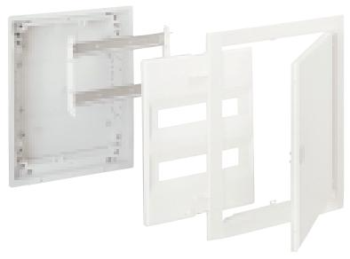
Box design:

Made of non warped, drop resistant, and non combustible plastic material (compliant with UL 94-V2 standard), with a large internal space and equipped with cable strain relief comb. There are pre formed cable entrances on the side and back.

Wall mounted grip is a standard configuration that can reduce installation depth or serve as a spacer for multiple distribution boxes installed side by side. It can be flipped to provide two insertion depths.

Installation method:

Support embedded installation, hollow wall installation can be achieved through the UZ 90 E hollow wall installation kit, without the need for a dedicated distribution box.

The equipment bracket adopts a snap on system, which can be quickly installed without tools. The DIN rail is double insulated, and the N/PE terminals and N-RCD terminals are plug-in. All clips comply with VBG 4 standards to prevent accidental contact.

Cover plate and door frame:

The cover plate is fixed with two 900 quick action locking screws, which can be sealed, and the slot width can be expanded from 12 modules to 14 modules.

The decorative frame and door are easy to disassemble and can adapt to uneven surfaces.

Product series and models

Basic version: No decorative frame and door, including box body, equipment bracket, movable DIN rail, cover plate, N/PE terminal, N-RCD clamp terminal, wall clamp, label system, etc. It is divided into four types according to module width: 12 (14), 24 (28), 36 (42), 48 (56), corresponding models are UK 510 BE, UK 520 BE, UK 530 BE, UK 540 BE, and the dimensions (HxWxD), niche dimensions, wall cut dimensions, and weight are given respectively.

Standard version and options: with decorative frame and door, there are various styles of decorative frame and door, such as:

Standard version: Alpine white (RAL 9003) powder coated steel plate material.

Art line “: Made of brushed stainless steel material.

“Additional line”: Photo frame doors made of brushed aluminum or coated with anodized color.

Color line “: There are metal coatings such as Bordeaux red, anthracite, midnight blue, etc.

Transparent door design.

Different styles are compatible with different base models and have corresponding internal and external dimensions.

control panel:

The front-end control panel can be used to monitor and operate building functions (such as lighting systems), using standard UK 500 components, with a sturdy aluminum frame and anodized front panel and safety lock.

There are three models (FPT 510 E, FPT 520 E, FPT 530 E) with different external dimensions, which can be decorated by the user or pre installed and printed by the factory.

Accessories and replacement parts

Including enclosure, wall clamp, quick action screws, hollow wall installation kit, surface installation kit, N and PE terminals, N-RCD terminals, labeling system, cable ties, screws, mounting plates, snap closures, safety locks, slot covers, cable entrances, vertical and horizontal partitions, etc., the product models that each accessory is compatible with are listed in detail.

Technical Standards and Certification

Compliant with DIN VDE 0603, DIN 43

871, German Institute of Engineers standard VDE 0100/729, etc., with an IP protection level of IP 30 and a rated current of 63A.

image.png

ABB contactors and overload relays

Product Series Overview

The document covers multiple contactor and overload relay series under ABB, with core products including:

Contactor:

AX series: suitable for low-voltage distribution and motor control, with a current range of 6A-1000A, supporting AC/DC coils, featuring compact design and high mechanical life (≥ 10 million cycles).

AF series: designed for frequent operation scenarios such as elevators and cranes, with a current range of 9A-400A and a mechanical lifespan of up to 30 million cycles.

A-series: Classic series, covering 12A-630A, supports multiple coil voltages, and is compatible with global standards.

Overload relay:

TA series: Thermal overload relay, used in conjunction with contactors, with a current range of 0.1A-630A, providing manual/automatic reset function.

TF series: Electronic overload relay with precise protection (overload, phase loss, locked rotor, etc.), supporting communication functions (such as Modbus), current range of 0.1A-800A.

Combination product: Pre assembled units for contactors and overload relays (such as AX+TA, AF+TF), simplifying selection and installation.

Core technical parameters and performance

Key indicators of parameter categories

Electrical performance – rated voltage: AC below 690V, DC below 250V (some models support higher voltages).

-Breaking capacity: It can reach 10 times the rated current under AC-3 load (such as AX18 with a breaking capacity of 100A at 400V).

-Coil power consumption: AC coil ≤ 15VA, DC coil ≤ 10W, energy-saving coil power consumption reduced by more than 50%.

Mechanical performance – Operating frequency: up to 1200 times/hour (AX series), AF series supports higher frequencies (such as 3600 times/hour).

-Protection level: The contactor body is IP20, and after installing a casing, it can reach IP65.

-Installation method: DIN rail installation (35mm) or screw fixation, supporting vertical/horizontal installation.

Protection Function – Overload Relay: The TA series achieves overload protection through bimetallic strips, while the TF series has an electronic trip curve (Class 10/20/30) and customizable protection parameters.

-Contactor: equipped with an arc extinguishing cover to reduce damage to the contacts caused by the arc, and supports reversible control (through mechanical interlocking).

Environmental adaptability – Operating temperature: -25 ° C to+70 ° C (some models -40 ° C to+70 ° C).

-Vibration resistance: 10-55Hz, amplitude 0.75mm; Impact resistance: 30g (11ms).

Selection and Application Guide

Selection criteria: Select the model based on the load type (motor, lighting, electric heating, etc.), rated current, operating frequency, protection requirements (overload, short circuit, etc.), and environmental conditions (temperature, humidity). The document provides a detailed selection table, including the current matching relationship under different load types (such as AC-1 resistive load, AC-3 motor load).

Typical application scenarios:

Industrial motor control (pumps, fans, conveyors).

Low voltage distribution system (distribution box, switchgear).

Building automation (air conditioning, elevators).

Renewable energy sources (photovoltaic inverters, wind power converters).

Installation and maintenance

Installation points:

Wiring: The main circuit uses copper or aluminum cables (with copper aluminum transition terminals), and the cross-sectional area of the control circuit wires is 0.5-2.5mm ², with a tightening torque of 0.5-2.5Nm (depending on the terminal specifications).

Spacing requirement: Contactors of different current levels must maintain a certain electrical clearance (such as 100A or above ≥ 15mm) to ensure heat dissipation and insulation.

Maintenance suggestion: Regularly check contact wear (replace when thickness ≤ 1mm), clean the arc extinguishing cover, test the accuracy of overload relay action, and avoid long-term operation in dusty and corrosive environments.

Certification and Standards

Compliant with international standards: IEC 60947-1/4 (contactors), IEC 60947-5-1 (overload relays).

Certification coverage: CE, UL, CSA, CCC, GL (Classification Society), etc., applicable to the global market.

Additional Information

Provide technical charts such as product size diagrams, wiring diagrams, trip curves (overload relays), and lifespan curves to assist in installation and debugging.

Contains environmental information: The product materials comply with the RoHS directive, and the proportion of recyclable parts is ≥ 90%.

Emphasize safety reminder: Installation should be operated by professional electricians, and maintenance should be carried out after power failure to avoid electric shock or mechanical injury.

ABB NTAC-0x pulse encoder interface module

Safety instructions

Warning types: including dangerous voltage warning, general warning, electrostatic discharge warning, reminding users to have professional electricians perform electrical installation and maintenance. Drivers and related equipment must be properly grounded. After power failure, wait for 5 minutes for the intermediate circuit capacitor to discharge, and use voltage indicating instruments to confirm the completion of discharge. At the same time, be aware of the risks that may arise from the automatic reset function of the driver.

Attention: Emphasize following the manufacturer’s operating instructions to avoid hazards such as electric shock.

Overview

Scope of application: Applicable to NTAC-02 (revised version C and above), NDIO-02 (revised version A and above), NAIO-03 (revised version A and above), and includes reference information from earlier versions (NTAC-01, NDIO-01, NAIO-01/02).

Module function:

NTAC-02: Provides a digital pulse encoder interface for obtaining precise speed or position feedback of the motor shaft.

NDIO-02: Provides 2 digital inputs and 2 relay outputs.

NAIO-03: Provides 2 analog inputs and 2 analog outputs, with signal resolution (12 bits) superior to standard analog I/O.

Communication link: Connected to the frequency converter through an optical DDCS protocol communication link, the module and NIOC standard I/O board usually form a circular connection on the CH1 channel of the NAMC board, which acts as the main station to cyclically poll other stations.

install

Module Node Number Setting: Different modules (NTAC, NDIO, NAIO) have their own node numbering rules set through DIP switches inside the module casing. The new settings will take effect when the module is powered on next time.

Mechanical installation: It can be installed inside or outside the drive. When installing outside, attention should be paid to wiring, space, environmental conditions, and grounding requirements. When installing inside, it should be operated by a professional electrician, following steps such as power-off, discharging, and removing the cover plate.

ACS 600 connection: Use fiber optic cables to connect to the NAMC/NDCO board of the driver, paying attention to the color coding of the connectors (blue for RXD, gray/black for TXD). Multiple modules are connected in a circular manner on the same channel, and the terminals connected to different modules vary depending on the application.

Detailed installation and configuration of each module

NTAC-02 pulse encoder interface module: introduces terminal identification, current consumption, wiring requirements (cable type, length, shielding grounding, etc.), encoder output type connection diagram (push-pull, collector open circuit, emitter open circuit), and programming method (set through driver parameters).

NDIO-02 digital I/O expansion module: including terminal identification, wiring recommendations, DI1 hardware filter suppression settings, and programming methods (activating communication through driver parameters).

NAIO-03 Analog I/O Expansion Module: Includes mode selection (unipolar/bipolar), input signal type selection (current/voltage), terminal identification, wiring requirements, programming methods (activates communication through driver parameters to ensure parameter settings correspond to module mode switches).

Appendix Information

Technical data: including detailed technical parameters such as I/O expansion links, enclosure of each module, installation, connectors, input and output.

Environmental conditions: lists the environmental requirements for temperature, humidity, vibration, impact, etc. of the module during operation, storage, and transportation.

Early version information: Introduces the differences, terminal identification, settings, and other information between NTAC-01, NDIO-01, NAIO-01/02 and their corresponding new versions.

​Install and start ABB NTAC-0x module

Installation preparation

Confirm compatibility

The module needs to be used in conjunction with the ACS 600 series frequency converter, and the application version must be ≥ V5.0 (standard application) or ≥ V4.2 (system application).

Check the encoder type (push-pull, open collector or open emitter) and prepare matching connecting cables.

Safe power outage

Disconnect the main power supply of the frequency converter and wait for 5 minutes until the intermediate circuit capacitor discharges completely.

Use a voltage indicator to confirm that there is no residual voltage.

Physical installation steps

1. Node number setting

Open the module casing and set the node number (range: 1-31) through the DIP switch.

Rule:

The NTAC module number needs to be an even number (such as 2, 4, 6…).

Node numbers within the same channel cannot be duplicated.

After the setting is completed, it will take effect when powered on again.

2. Mechanical installation

Internal installation (recommended):

Remove the cover plate of the frequency converter and insert the module into the CH1 channel of the NAMC board or NDCO board.

Connect the RXD (blue interface) and TXD (gray/black interface) of the module using fiber optic cables to form a circular topology.

External installation:

Choose a dry and ventilated location to ensure that the ambient temperature is between -25 ° C and+55 ° C.

Fix the module with M4 screws and maintain a minimum spacing of 50mm.

3. Encoder connection

Select the corresponding terminal based on the encoder type (such as A+/A -, B+/B -).

Wiring requirements:

Use shielded cables with both ends of the shielding layer grounded.

The encoder cable should be kept at least 100mm away from the power cord to avoid interference.

Maximum cable length: push-pull encoder ≤ 100m, differential encoder ≤ 300m.

Electrical connection

1. Power connection

The module is powered internally by the frequency converter and does not require additional power supply.

2. Fiber optic communication connection

Connect the RXD (receiver) of the module to the TXD (transmitter) of the previous node to form a circular link.

The TXD of the last module needs to be connected back to the NAMC board or NDCO board of the frequency converter.

3. Encoder signal connection

Push pull encoder: directly connected to the digital input terminal of the module.

Differential encoder: Connected after conversion by a differential receiver.

Troubleshooting

communication failure

Check if the fiber optic connection is secure and if the interface is clean.

Confirm that there are no conflicts in the node numbers and that all module numbers are even.

Encoder signal loss

Check if the encoder power supply is normal (usually+5V or+24V).

Use an oscilloscope to check if the encoder output waveform is stable.

Parameter not effective

Restart the frequency converter and ensure that the parameters are saved to non-volatile memory.

Precautions

Static protection: Wear an anti-static wristband before operation to avoid touching the circuit board.

Environmental requirements: Avoid installation in damp, dusty, or strong electromagnetic interference environments.

Maintenance: Regularly clean the module’s heat dissipation holes and check for dust or damage to the fiber optic interface.

ABB electronic timer CT-APS.22

Basic characteristics of the product

Function: Single function delay shutdown timer with 2 conversion contacts (2 c/o contacts).

Power supply voltage: Supports 24-48 V DC and 24-240 V AC.

Time Range: 10 time ranges are available, covering 0.05 s to 300 h. The time range can be pre selected by rotating the switch, and the front-end potentiometer has a direct reading scale for fine adjustment.

Status indication: 2 LED indicator lights, green LED (U/T) displays the control power supply voltage application and timing status (flashing during timing), yellow LED (R) displays the output relay power status.

Size: Width 22.5 mm, compact design.

Protection function: Optional sealable transparent cover (COV.01) to prevent unauthorized changes to time values; Integrated Tag Label (MAR.01).

Certification: Passed UL 508, CAN/CSA C22.2 No.14, GL, GOST, CB scheme, CCC and other certifications, with CE and C-Tick marks.

Working mode and function

Delay shutdown function: Continuous control of power supply voltage timing is required. When the control inputs A1-Y1/B1 are closed, the output relay is immediately powered on; When the input is disconnected, there is a delay and the green LED flashes; After the delay is over, the output relay will be powered off and the green LED will remain on. If the input closes again before the delay ends, the delay will reset and the output relay status will remain unchanged; When the control power supply is interrupted, the output relay will be powered off and reset with a delay.

Terminal description: The first conversion contact is 15-16/18, the second is 25-26/28, the control power is connected to A1-A2, and the control input is A1-Y1/B1.

Technical Parameter

Input circuit:

Control power supply voltage tolerance: 24-48 V DC is -15…+10%, 24-240 V AC is -15…+10%.

Typical current/power consumption: 16 mA at 24 V DC, 60 mA at 24-48 V DC (as needed), 36 mA at 115 V AC (as needed), etc.

Frequency range (AC): 47-63 Hz.

Power failure buffer time: 24 V DC minimum 15 ms, 230 V AC minimum 20 ms.

Control circuit: The control input is voltage dependent trigger, anti reverse polarity, non polarized, switchable parallel load, maximum cable length of 50 m (100 pF/m), minimum control pulse length of 20 ms, control input current of 1.2 mA at 24 V DC and 8 mA at 230 V AC.

Timing circuit: Recovery time<80 ms, repeatability accuracy (constant parameter) Δ t<± 0.2%, accuracy within voltage tolerance Δ t<0.004%/V, accuracy within temperature range Δ t<0.03%/° C.

Output circuit: rated working voltage of 250 V, minimum switching voltage/current of 12 V/10 mA, AC rated working current (IEC/EN 60947-5-1) AC12 (230 V, resistive) 4 A, AC15 (230 V, inductive) 3 A, DC rated working current DC12 (24 V, resistive) 4 A, DC13 (24 V, inductive) 2 A; mechanical life of 30 × 10 ⁶ switching cycles, electrical life (AC12230 V, 4 A) 0.1 × 10 ⁶ times; The maximum rated value of the short-circuit protection fuse is 6 A for normally closed contacts and 10 A for normally open contacts.

General data: Duty cycle 100%, dimensions (width x height x depth) 22.5 × 78 × 100 mm, weight 0.128 kg, installation position arbitrary, minimum distance from other equipment not required during normal operation, installed on DIN rail (IEC/EN 60715), enclosure/terminal protection level IP50/IP20.

Electrical connection: Screw connection, wire specification (fine stranded wire with wire end sleeve) 2 × 0.75-2.5 mm ² (2 × 18-14 AWG), wire stripping length 7 mm, tightening torque 0.6-0.8 Nm.

Environment and Isolation Data

Environmental data: working environment temperature -25…+60 ° C, storage environment temperature -40…+85 ° C, withstand 6 × 24-hour cycles of humidity and heat (55 ° C, 95% RH); The tolerance to vibration, impact and other environmental factors meets relevant standards.

Isolation data: rated insulation voltage of output circuit 300 V, input/output circuit 500 V; power frequency withstand voltage test (routine/type) 2.0 kV (50 Hz, 1 s)/2.5 kV (50 Hz, 1 min); Basic insulation (input/output) 500 V, protective isolation 250 V; pollution level 3, overvoltage category III.

Standards and Compatibility

Compliant with product standards such as IEC 61812-1, EN 61812-1+A11, as well as directives such as EMC, low voltage, RoHS, etc.

In terms of electromagnetic compatibility, both anti-interference and interference emission comply with relevant standards and level requirements.

ABB Small, compact Thermostat KTO 011 / KTS 011

Basic Product Information

KTO 011: Normally closed thermostat, which can be used as a contact circuit breaker for heaters.

KTS 011: Normally open thermostat, which can be used to adjust the contact closure of filter fans and heat exchangers, or switch signal devices when the temperature exceeds the limit.

Features: Large setting range, small size, easy installation, high switch performance.

Technical Parameter

Switch temperature difference: 7K (tolerance ± 4K)

Sensor element: Thermostatic bimetallic strip

Contact type: Quick acting contact

Contact resistance:<10mOhm

Service life:>100000 cycles

Maximum switch capacity: 250VAC, 10 (2) A; 120VAC,15(2)A; DC 30W

Electromagnetic compatibility: compliant with EN 55014-1-2, EN 61000-3-2, EN 61000-3-3 standards

Connection method: 2-pole terminal, suitable for 2.5mm ², clamping torque 0.8Nm

Installation method: Suitable for clamp on 35mm DIN rail (EN50022) or for EF 118 series outlet filter

Shell: UL94 V-0 grade plastic, light gray

Size: 60 × 33 × 43mm

Weight: Approximately 40g

Installation location: Variable

Working/Storage Temperature: -20 to+80 ° C (-4 to+176 ° F)/-45 to+80 ° C (-49 to+176 ° F)

Protection level:IP20

Model and certification information

The models and certifications corresponding to different setting ranges are shown in the following table:

Setting range, normally closed (NC) model, normally open (NO) model, certification:

0 to+60 ° C, 01140.0-00, 01141.0-00, VDE

-10 to+50 ° C, 01142.0-00, 01143.0-00, VDE

+20 to+80 ° C, 01159.0-00, 01158.0-00, VDE

+32 to+140 ° F, 01140.9-00, 01141.9-00, UL File No. E164102

+14 to+122 ° F, 01142.9-00, 01143.9-00, UL File No. E164102

0 to+60 ° C, 01146.9-00, 01147.9-00, UL File No. E164102

Installation and Commissioning

Installation related basic information

Installation method: It can be installed using clips suitable for 35mm DIN rails (compliant with EN50022 standard), or it can be installed on the EF 118 series outlet filter.

Connection method: Using 2-pole terminals, suitable for 2.5mm ² wires, with a clamping torque of 0.8Nm.

Installation position: Flexible selection, not fixed position.

Debugging related tips

Due to the lack of clear debugging steps in the document, combined with the general usage logic of thermostats, the following aspects can be focused on during debugging:

Temperature setting: Adjust the temperature threshold within the specified setting range of the product according to actual needs (different models have different setting ranges, such as 0 to+60 ° C, -10 to+50 ° C, etc.).

Functional testing: By changing the ambient temperature, observe whether the switch status of the thermostat meets expectations (KTO 011 is normally closed and opens when the set temperature is reached); KTS 011 is a normally open type that closes when the set temperature is reached to verify its proper functioning.

ABB low-voltage AF contactor AF400… AF460

Product overview

Product positioning: ABB’s AF contactor series is a benchmark product in the industry. Its integrated electronic control coil has multiple advantages compared to traditional products, and combined with ABB’s rich product portfolio, it can achieve the optimization of each configuration.

Scope of application: AF400… AF460 three pole contactors are designed to control motors ranging from 200 to 250 kW (AC-3) at 400V AC or 250 to 400 hp at 480V AC UL, as well as switch power circuits up to 700A (AC-1) or 650A UL/CSA universal.

Product features:

Using AF technology, the control voltage range is wide (48… 500V 50/60Hz and 24… 500V DC), and only 4 coils are needed to cope with large control voltage changes, reducing panel energy consumption and ensuring stable operation in unstable networks.

Built in PLC control and surge protection, the solution is compact.

Adopting a block design, it is easy to expand additional auxiliary contact blocks and various accessories.

Product compliance

REACH regulation: AF contactors and related accessories are classified as articles and will not intentionally release any substances or preparations under normal and reasonably foreseeable conditions of use. ABB continues to communicate with the supply chain and collect information on suppliers’ compliance with REACH regulations.

SVHC substances: ABB continuously evaluates the content of highly concerned substances (SVHC) in its products. As far as we know, the content of SVHC substances in AF contactors and related accessories does not exceed 0.1% by weight.

RoHS II Directive: AF contactors and related accessories fall within the scope of the 2011/65/EU Directive (RoHS II) and its 2015/863 amendments, and are applicable from July 22, 2019.

WEEE Directive: Compliant with the 2012/19/EU Directive of the European Community on Waste Electrical and Electronic Equipment (WEEE Directive).

Product Safety

Ensure basic health and safety requirements are met by complying with applicable product and safety standards.

The third-party testing laboratory (STIEE/TL030) has conducted product and safety standard validation in accordance with EN ISO/IEC 17025 European standards and the IECEE CB program, and has issued a CB certificate.

Material Declaration

Taking AF460-30-11-70 (representing AF400… AF460 series contactors) as an example, the total weight is 9621 grams, and its composition materials and proportions (weight percentage) are as follows:

Proportion of materials

Steel: 51.2%

Copper: 8.5%

BMC:24.9%

Precious metals: 0.1%

PA:8.4%

SMC:4.0%

PCBA:1.0%

FRP:0.9%

PBT:0.7%

HNBR:0.1%

POM:0.1%

FKM:0.02%

Total: 100.0%

Packaging

Taking AF460-30-11-68 as an example, the total weight of the packaging is 205 grams, and the material composition and proportion are:

Cardboard: 72%

Plastics: 28%

Total: 100%

Among them, the cardboard and paper used for product packaging are made of recycled fibers and are 100% recyclable; The polymer film used is labeled with an appropriate identification code and is recyclable.

ABB KPM Sheet Break Detector – KB2 

Product overview

KPM KB2 is a non-contact paper breakage detector launched by ABB, with hundreds of installation cases worldwide, recognized as an excellent paper breakage detection device in the market. It can be installed above or below the paper web, suitable for environments with high dust, steam, high temperature, and limited space. It keeps the sensor head clean through air blowing and can reliably monitor paper breakage in harsh environments.

Core functions and features

Flexible detection light source: equipped with RGB or infrared light sources, it can perform well in various paper and cardboard products and applications regardless of the color of the paper and cardboard. RGB color measurement can handle all paper, mesh, and woolen colors, ensuring reliable fracture detection. In addition to open traction applications, it can also detect fractures in woolen, mesh, and even drum backgrounds.

Fast fracture detection: Using digital signal processing technology, thousands of measurements are taken of all signals per second, and the backlight intensity is measured to resist the influence of environmental light changes. The minimum delay for fracture detection is only 15ms, and users can select the number of measurement cycles for fracture alarm through digital filtering.

Convenient setup and operation: Equipped with a large display screen and a logical user interface, the fracture detection setup can be easily completed by selecting the measurement value with the largest signal difference. The fracture and maintenance alarm can be connected to PLC or DCS, and color measurement PC software can also be selected for monitoring, including data collection function.

Adapt to harsh environments: It can maintain high reliability even in high humidity environments. When the sensor head is exposed to high temperatures, the electronic unit can be installed outside the machine cover through fiber optic cables.

Specification parameters

Environmental temperature sensor head and fiber optic cable: -10-180 º C (15-356 º F); Electronic unit: -10-60 º C (15-140 º F)

Fiber optic cable KPM KB2/6:6m (20ft); KPM KB2/9:9m(30ft); KPM KB2/12:12m(40ft)

Fiber optic cable conduit requires a flexible airtight conduit with an inner diameter of at least 19mm (3/4 “), which can be optionally selected

19mm (three-quarters “) BSP conduit connection

Install the sensor 5-30cm (2-12 “) away from the paper web

LED pulse frequency 1kHz

Power supply 90-264VAC, 50/60Hz or 24VDC

Power consumption 15W

Shell protection level IP 66 (Nema 4x)

Blow air connection dry instrument air, 6-4mm (¼ “) connector, normal consumption 80l/min (21gpm)

Digital output with 2 normally open or normally closed contacts, maximum 250VAC, 2A; 220VDC、2A, Used for breaking signals and maintenance alarms

Alarm output delay: minimum 15ms after actual fracture

Analog output (optional) 3 4-20mA, maximum 600 Ω (ohms), isolated

Dimensions (length x height x width) and weight: Electronic unit: 323 x 237 x 70mm (12.7 x 9.3 x 2.8 “), 3kg (6.6lbs); Sensor head: diameter 33mm (1 1/4 “), stainless steel 316, tube length 1500mm (59”), 4kg (9lbs)

Application scenarios

Mainly used in the pulp and paper industry, it is used to monitor the breakage of paper sheets during the production process of paper and cardboard. It can be installed in different positions of the paper machine, such as the mesh section, press section, drying section, etc., to detect paper sheet breakage in a timely manner and issue alarm signals, so that operators can quickly take measures to reduce production losses caused by paper sheet breakage, improve production efficiency and product quality.

Brand background

This product is produced by ABB, a leading global electrical and automation enterprise with operations in multiple countries and regions around the world. ABB has deep technological accumulation and extensive influence in the fields of power, industry, transportation, and infrastructure. It has always been committed to technological innovation and provides advanced solutions for various industries. KPM KB2 paper breakage detector is one of ABB’s important products in the automation solutions of pulp and paper industry, reflecting ABB’s technical strength in this field and deep understanding of industry needs.

KPM Sheet Break Detector - KB2 Ranger model - Process measurements ...

ABB TP854 base plate

ABB TP854 base plate

Product Overview

AO845A is an analog output module specially designed by ABB for industrial automation scenarios, belonging to the S800 I/O family. This module is mainly used to convert the digital signals inside the controller into analog signals, in order to drive actuators or other analog devices. It plays a key role in industrial automation and control systems, and can achieve precise control of various industrial processes. It supports single redundancy or redundant applications and has 8 unipolar analog output channels, which can meet the diverse control needs of complex industrial systems. At the same time, the module has a periodic self diagnostic function, which can monitor the real-time operation status of the module and ensure the stable and reliable operation of the system.

Brand background

ABB, as a globally renowned technology leader in the field of electrical and automation, has a long history of over 140 years. The company operates globally and has over 105000 employees. ABB has always focused on technological innovation, deeply integrating engineering experience with digital technology to provide advanced solutions for various industries, helping customers achieve efficient operations, improve energy efficiency and production efficiency, and promote sustainable development in various industries. In the field of industrial automation, ABB relies on its profound technical accumulation and rich project experience, and its products are widely used in various industries, trusted by global customers.

Basic information

Product model: TP854 (or TP854A, TP854B)

Product Code: 3BSE025349R1

Product Description: A base plate designed specifically for CI854, CI854A, and CI854B, belonging to the Modular Termination-Unit.

Package: Yes CI854K01(3BSE025961R1)、CI854AK01(3BSE030220R1)、CI854BK01(3BSE069449R1) The components of the kit.

​Size and weight

Product net depth/length: 216mm

Product net height: 49.5mm

Product net width: 72mm

Net weight of product: 0.234kg

Core functions

Analog signal output: It can output 4… 20 mA standard analog signals, which are used to drive devices that require continuous adjustment such as regulating valves, frequency converters, and motor controllers, achieving precise control of industrial processes.

HART communication: Supports HART pass through communication function, facilitating device status monitoring and remote parameter configuration, and improving system management efficiency. Only point-to-point communication is supported, and the channel used for HART communication requires an output filter to be enabled.

Self diagnostic function: Periodically perform self diagnosis, monitor and report multiple faults in real time. External channel errors, such as low output circuit supply voltage, output current less than the set value, and set value greater than 1 mA (open circuit), will be reported (only reported on active channels); Internal channel error, reported when the output circuit cannot provide the correct current value, the redundant centering module will be instructed by the module bus master device to enter an error state; Module errors, including output transistor errors, short circuits, checksum errors, internal power supply errors, status link errors, watchdog or erroneous OSP behavior, will be reported.

Working principle

The control system sends digital signals to the AO845A module, and the digital to analog converter (DAC) inside the module converts the received digital signals into analog signals. Afterwards, the analog signal is output to the external control device through the analog output channel. For example, in a temperature control system, the PLC calculates a control signal based on the difference between the current temperature value and the set temperature, and sends it in digital form to the AO845A module. The AO845A module converts it into a corresponding 4-20 mA analog current signal output to control the working power of the heater and adjust the temperature.

Key advantages

High reliability: Equipped with comprehensive self diagnostic functions and short-circuit protection mechanisms, it can promptly detect and handle faults, ensuring stable operation in complex industrial environments. Through various international certifications such as CE, UL, etc., it meets strict electrical safety standards and can adapt to the safety requirements of different regions and industries.

Flexible compatibility: Supports single redundancy or redundant applications, can be used in conjunction with multiple MTU (module terminal units), suitable for industrial automation systems of different architectures, and has strong universality and compatibility.

Convenient communication: With the help of HART communication technology, seamless integration with various devices can be achieved, facilitating real-time data exchange and device diagnosis, facilitating remote management and maintenance, reducing manual intervention, and improving overall system operation and maintenance efficiency.

Precise control: With a resolution of 12 bits and a maximum error as low as 0.1%, it can accurately output analog signals, meeting the extremely high requirements for control accuracy in industrial application scenarios.

Precautions

Installation aspect: During installation, relevant electrical specifications and operation guidelines should be followed to ensure the correct installation of modules and correct circuit connections, in order to prevent malfunctions caused by improper installation. The module size is compact, and the installation space should be reasonably planned to ensure good heat dissipation.

Signal configuration: It is necessary to correctly configure the signal mode (such as active or passive mode) according to the actual application scenario. For equipment operating in different explosion-proof areas, corresponding configuration rules should be followed.

Wiring requirements: Use shielded cables for process connections, especially when using HART communication, to reduce electromagnetic interference and ensure the stability and accuracy of signal transmission.

Address setting: For devices with PROFIBUS PA, the bus address should be checked or configured before startup to ensure that the address is within the valid range (0… 125) and unique within the network segment.

Maintenance: Regularly check the working status of the module, observe the front LED indicator lights, and promptly troubleshoot and handle any abnormalities. When the system malfunctions, targeted maintenance can be carried out based on the diagnostic information of the module.

ABB AO845A Analog Output Module

Product overview

AO845A is an analog output module suitable for System 800xA systems, supporting single redundancy or redundant applications, equipped with 8 unipolar analog output channels. The module has a periodic self diagnostic function, which can monitor various fault states such as external channel errors, internal channel errors, and module errors, ensuring operational reliability.

Core functions and features

Output capability: 8 channels of 4-20 mA, meeting the analog signal output requirements of industrial sites.

Redundancy support: can be used in redundant application scenarios to enhance system stability.

Isolation protection: 8 channels are isolated from ground as a group, and the analog output has short-circuit protection function (for ZP or+24 V).

Communication function: Supports HART pass through communication, facilitating device status monitoring and parameter configuration.

Self diagnosis: Periodically self diagnose and promptly report various faults, including external channel errors (such as low supply voltage, open circuit, etc.), internal channel errors (such as abnormal output circuit), and module errors (such as output transistor faults, short circuits, checksum errors, etc.).

Specification parameters

Basic parameter model: AO845A; Product Code: 3BSE045584R1; Type: Analog output; Signal specification: 4.20 mA; Number of channels: 8; Does it support HART: Yes; Does it support SOE: No; Redundancy: Support; High integrity: No; Intrinsic safety: No; Mechanical specification: S800

Performance parameter resolution: 12 bits; Isolation method: Group level and grounding isolation; Over/under range: ± 15%; Maximum output load: 750 Ω; Maximum error: 0.1%; Temperature drift: maximum 50 ppm/° C; rise time: 23 ms when output filter is disabled, maximum 4 mA/12.5 ms when enabled; Input filter (0-90% rise time): 23 ms (0-90%), maximum 4 mA/12.5 ms; Update cycle: 10 ms; Current limit: Short circuit protection current limiting output; Maximum on-site cable length: 600 meters (656 yards)

Electrical parameters: Rated insulation voltage: 50 V; Dielectric test voltage: 500 V AC; Power consumption: typical 3.5 W;+5 V Modulus current consumption: maximum 125 mA;+24 V external current consumption: 218 mA

Diagnosis and indication front-end LED: F (fault), R (operation), W (warning) O(SP); Monitoring status indication: module error, module warning, channel error

Environment and Certification CE Mark: Yes; Electrical safety: compliant with IEC 61131-2, UL 61010-1, UL 61010-2-201; Dangerous Place Certification: C1 Div2 cULus, C1 Zone2 cULus, ATEX Zone 2; Classification society certification: BV, DNV-GL, LR; Protection level: IP20 (according to IEC 60529); Corrosive environment grade: ISA-S71.04 G3; Working climate conditions: 0 to+55 ° C (storage -40 to+70 ° C), relative humidity 5-95%, no condensation (compliant with IEC/EN 61131-2); Pollution level: Level 2 (according to IEC 60664-1); Mechanical working conditions: comply with IEC/EN 61131-2; EMC: Complies with EN 61000-6-4 and EN 61000-6-2; Overvoltage category: compliant with IEC/EN 60664-1 and EN 50178; Equipment category: Class I (according to IEC 61140, grounding protection); Maximum ambient temperature: 55 ° C (131 ° F), 40 ° C (104 ° F) for compact MTU vertical installation; Compliant with RoHS (Directive 2011/65/EU) and WEEE (Directive 2012/19/EU)

Compatible with MTU: TU810, TU812, TU814, TU830, TU833, TU842, TU843, TU852; Key control code: DB

Size and weight width: 45 mm (1.77 inches); Depth: 102 mm (4.01 inches), including connector 111 mm (4.37 inches); Height: 119 mm (4.7 inches); Weight: 0.21 kg (0.46 pounds)

Related products

Including TU810V1, TU812V1, TU814V1, TU830V1, TU833, TU842, TU843, TU852, etc.

Key advantages

High reliability: Equipped with comprehensive self diagnostic functions and short-circuit protection, it can promptly detect and report faults, ensuring stable system operation.

Flexible compatibility: Can be used in conjunction with multiple MTUs, suitable for single redundant or redundant application scenarios, and adaptable to different system architecture requirements.

Convenient communication: Supports HART protocol, facilitating remote monitoring and configuration, and improving system management efficiency.

Strong environmental adaptability: capable of working in a wide range of temperature, humidity, and corrosive environments, compliant with multiple international standards and certifications, suitable for complex industrial environments.

AO845A 3BSE045584R1 ABB PLC Analog Output Module S/R HART 8 CH S800 I/O DCS

ABB FS450R12KE3+AGDR-71C Integrated Circuit

Product Overview

FS450R12KE3+AGDR-71C is an integrated circuit product launched by ABB, which belongs to the IGBT related module combination. At present, there are 500 pieces of brand new original inventory, which can provide key circuit control functions for various electronic devices and industrial control systems. It plays an important role in the field of electronic component applications and can meet the circuit control needs in different scenarios.

Brand background

This product is manufactured by ABB company. ABB is a globally renowned electrical and automation enterprise with a history of over 130 years. Its business covers multiple countries and regions around the world, and it has deep technological accumulation and extensive influence in fields such as power, industry, transportation, and infrastructure. ABB has always been committed to technological innovation. Its products are known for their high quality, high reliability and progressiveness. They occupy an important position in the global market and provide advanced solutions and product support for many industries.

Specification parameters

Due to the lack of detailed specifications for the product in the existing information, combined with the relevant categories of IGBT modules and common industry standards, it is speculated that the product may have the following similar specifications (specific to the product datasheet):

Voltage level: may be suitable for medium to high voltage scenarios, such as 1200V commonly seen in related product series.

Current capacity: As a power device, it may have a high current carrying capacity to meet the power requirements of industrial equipment.

Packaging form: Adopting packaging suitable for industrial applications, with good heat dissipation performance and mechanical strength to adapt to complex industrial environments.

Core functions

As an integrated circuit product, its core functions may include achieving efficient switch control of the circuit. In scenarios such as power conversion and motor drive, it can quickly switch circuit states, control current on/off, and effectively manage and distribute power. At the same time, it may have certain protection functions, such as overcurrent protection, overvoltage protection, etc., to ensure the safe operation of circuits and related equipment.

Working principle

It is speculated that its working principle is based on the working characteristics of IGBT (Insulated Gate Bipolar Transistor), which controls the gate voltage to achieve the on and off of the transistor. When a forward voltage is applied to the gate, the device conducts and current can pass through; When the gate voltage is removed or a reverse voltage is applied, the device is turned off and the current is cut off. AGDR-71C may serve as a driving module to provide suitable driving signals for FS450R12KE3, ensuring its stable and reliable operation and achieving precise control of the circuit.

Key advantages

Reliable Quality: Made by ABB, following strict quality control standards, ensuring 100% functional integrity and maintaining stable performance over long periods of use.

Stable supply: Currently, there are 500 pieces in stock, and delivery can be made within 2-3 days after payment, which can quickly respond to customer needs and reduce project delays caused by stock shortages.

Widely applicable: As a universal integrated circuit product, it can be applied to various electronic devices and industrial control systems, with strong universality and compatibility.

Precautions

Installation and use: During installation, it is necessary to follow relevant electrical specifications and operating instructions to ensure correct connection of circuits and avoid product damage or circuit failure caused by improper installation.

Storage conditions: It should be stored in a dry, ventilated, and non corrosive gas environment, avoiding direct sunlight and high temperature environments to prevent product performance from being affected.

Static electricity protection: Effective static electricity protection measures should be taken during the handling process, such as wearing anti-static wristbands, to prevent static electricity from damaging the product.

Application scenarios

FS450R12KE3+AGDR-71C can be widely used in the field of industrial automation, such as motor drive systems, power converters, uninterruptible power supplies (UPS) and other equipment, to achieve power conversion, control and distribution. In the field of new energy, inverters such as wind and photovoltaic power generation may also play an important role in ensuring efficient and stable energy conversion processes. In addition, there is potential application value in electronic devices related to rail transit, household appliances, and other fields.

全新FS450R17KE3/AGDR-71CS AGDR-72CS 450A 1700V 电源模块配套-阿里巴巴

Search for products

Back to Top
Product has been added to your cart