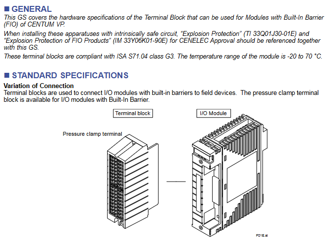
Product type: Pressure Clamp Terminal Block, a key intermediate component for signal transmission in industrial control systems
Applicable system: Designed specifically for the Yokogawa CENTUM VP control system, only compatible with FIO modules with built-in In Barrier in this system
Core function: To achieve stable circuit connection between I/O modules with built-in barriers and field devices, playing a role in signal conversion, fixed wiring, and ensuring transmission reliability. It is widely used in signal acquisition and control scenarios of industrial automation
Compliance standard: Compliant with ISA S71.04 class G3 standard, which specifies requirements for the environmental adaptability and safety performance of industrial process measurement and control equipment, ensuring stable operation of terminal blocks in complex industrial environments
Temperature adaptation range: -20 ℃ to 70 ℃, covering the temperature conditions of most industrial sites (such as factory workshops, control rooms, outdoor equipment areas, etc.), with strong environmental adaptability
Model system and core specifications
(1) Model classification logic
This series of terminal blocks is divided into two core series based on redundancy design. Each series is subdivided into specific models according to application types. The suffix code for all models is fixed at -0, with no other optional configurations. The classification logic is clear, making it easy for users to quickly select according to their actual needs
Single series: The model suffix is “S”, suitable for conventional industrial scenarios without redundancy requirements, with a simple structure and controllable cost
Dual Redundancy Series: The model suffix is “D” and is suitable for critical industrial scenarios that require extremely high system stability and reliability (such as core control links in industries such as chemical, power, and petroleum). The dual redundancy design ensures signal continuity in the event of a failure
(2) Detailed explanation of core specifications for all models
Model Application Type Channel Number Adaptation I/O Module Name Weight Core Adaptation Scenario
ATSA3S Analog Input (Single) 8-Point (8-Channel) ASI133 0.2 kg Analog Signal Acquisition in Conventional Scenarios, such as Input of Continuous Variables such as Temperature, Pressure, Flow, etc
ATSA3D analog input (Dual Redundant) 8-Point (8-channel) ASI133 analog signal acquisition under critical scenarios of 0.3 kg, ensuring uninterrupted signal acquisition, such as temperature acquisition of chemical reaction kettle
ATSS3S analog output (Single) 8-Point (8-channel) ASI533 0.2 kg analog signal output in conventional scenarios, such as controlling valve opening, adjusting pump speed, etc
ATSS3D analog output (Dual Redundant) 8-Point (8-channel) ASI533 analog signal output under critical scenarios of 0.3 kg, such as emergency stop control signal and core equipment speed control signal output
ATST4S thermocouple/mV (Single) 16 Point (16 channel) AST143 0.2 kg Temperature measurement signal or millivolt level small signal acquisition for thermocouples in conventional scenarios, such as furnace temperature and pipeline temperature monitoring
ATST4D thermocouple/mV (Dual Redundant) 16 Point (16 channel) AST143 high-precision temperature or small signal acquisition in critical scenarios of 0.3 kg, such as temperature monitoring in aerospace component processing
ATSR3S RTD/PAT (Single) 8-Point (8-Channel) ASR133 0.2 kg Thermal Resistance (RTD) temperature measurement or Potentiometer (POT) signal acquisition in conventional scenarios, such as equipment bearing temperature monitoring
ATSR3D RTD/PAT (Dual Redundancy) 8-Point (8-channel) ASR133 high-precision temperature or potentiometer signal acquisition in critical scenarios of 0.3 kg, such as temperature monitoring of nuclear power equipment
ATSB4S Digital Input (Single) 16 Point (16 Channel) ASD143 0.2 kg Digital Signal Input for Conventional Scenarios, such as Limit Switch Status and Equipment Operation Status (Run/Stop) Detection
ATSB4D Dual Redundant 16 Point ASD143 0.3 kg digital signal input for critical scenarios, such as emergency stop button signal and safety door switch status detection
ATSD3S digital output (Single) 8-Point (8-channel) ASD533 0.2 kg digital signal output in conventional scenarios, such as control indicator light on/off, relay on/off, small pump start/stop, etc
ATSD3D Digital Output (Dual Redundancy) 8-Point (8-channel) ASD533 Digital Signal Output for 0.3 kg Key Scenarios, such as Fire Alarm Signal Output, Emergency Cut off Valve Control Signal, etc
(3) Summary of Key Characteristics of Specifications
Channel number pattern:
8-channel models: a total of 8 types (4 single channel+4 dual redundant), covering analog input/output RTD/POT、 Four major categories of applications for digital output, meeting most conventional signal transmission needs
16 channel models: 4 types in total (2 single channel+2 dual redundant), only suitable for thermocouple/mV and digital input applications, suitable for scenarios requiring high-density signal acquisition, reducing the number of terminal block installations
Reason for weight difference: The single channel series is uniformly 0.2kg, and the dual redundancy series is uniformly 0.3kg. The weight increase is due to the additional hardware components such as circuits and wiring terminals required for the dual redundancy design, ensuring the implementation of redundancy functions
Module adaptation uniqueness: Each terminal block model corresponds to only one specific I/O module and cannot be mixed across models to avoid signal transmission failures or equipment damage caused by module and terminal block incompatibility
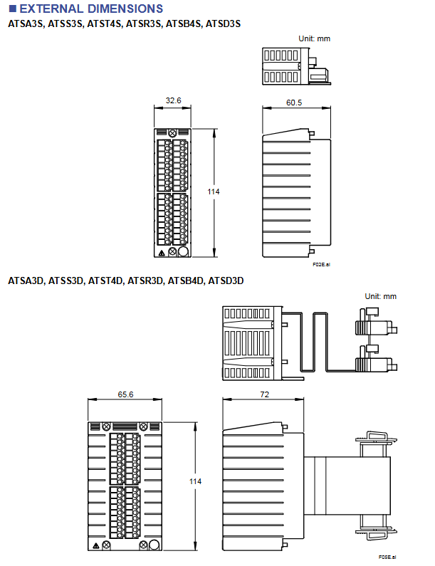
External dimensions and installation compatibility
(1) Size specification classification
The size of the terminal block is directly related to the redundancy design, and all models within the same series have identical dimensions for standardized installation layout. The specific specifications are as follows:
Series types include model size parameters (unit: mm), reference drawings, installation and adaptation scenarios
Single channel series ATSA3S, ATSS3S, ATST4S, ATSR3S, ATSB4S, ATSD3S length x width x height: 32.6 x 60.5 x 114 F02E.ai is suitable for control cabinet layouts with limited installation space and no need for redundant design, and can be densely arranged
The dual redundant series ATSA3D, ATSS3D, ATST4D, ATSR3D, ATSB4D, ATSD3D length x width x height: 65.6 x 72 x 114 F05E.ai is suitable for the layout of control cabinets in critical control areas and requires a certain amount of installation space to ensure the heat dissipation and maintenance convenience of redundant components
(2) Dimensional design features
Height uniformity: All models have a height of 114mm, which facilitates the planning of installation positions according to the floor height inside the standard control cabinet and improves the cleanliness of the installation layout
Width differentiation: The width of the dual redundant series (72mm) is greater than that of the single channel series (60.5mm), and the length (65.6mm) is greater than that of the single channel series (32.6mm), adapting to the spatial requirements of its internal redundant structure
Standardized design: The dimensions comply with industrial equipment installation specifications and can seamlessly adapt to other supporting equipment of the Yokogawa CENTUM VP system (such as I/O modules, control cabinet rails, etc.), reducing installation difficulty
Model coding rules and ordering requirements
(1) Detailed explanation of coding rules
Explanation of optional/fixed values for the meaning of coding components
The prefix (such as ATSA, ATSS, etc.) application type identification ATSA (analog input), ATSS (analog output), ATST (thermocouple/mV), ATSR (RTD/PAT), ATSB (digital input), ATSD (digital output) prefix directly corresponds to the core application functions of the terminal block, making it easy to quickly identify
Intermediate numbers (such as 3S, 3D, 4S, 4D, etc.) indicate the number of channels and redundancy types. 3S (8 channels+single channel), 3D (8 channels+double redundancy), 4S (16 channels+single channel), 4D (16 channels+double redundancy) numbers “3” correspond to 8 channels, and “4” corresponds to 16 channels; The letters “S” and “D” distinguish redundant types
Suffix code configuration identifier -0 (fixed value) All models use a unified suffix code, with no additional optional configurations, simplifying the selection and ordering process
(2) Ordering requirements
Users need to specify the complete model (including suffix code) when placing an order, for example:
Conventional simulation input scenario: Order “ATSA3S-0”
Key scenario digital output: Order “ATSD3D-0”
Due to the fixed suffix code of -0, the core needs to confirm the model body composed of the prefix and the middle digit to ensure a complete match with the actual application type, channel number, and redundancy requirements.
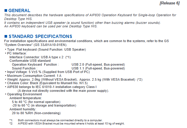
Product Name: AIP830 Single Circuit Operation Keyboard
Applicable equipment: Desktop HIS (Human Interface Station)
Core features: Integrated independent USB speaker (sound function)+buzzer alarm (electronic buzzer), 1 HIS corresponds to 1 keyboard
Manufacturer: Yokogawa Electric Corporation (2-9-32 Nakamachi, Musashino City, Tokyo, Japan)
Document version: Release 6, early February 2015, second edition on January 17, 2020 (document number GS 33J50C32-01EN)
Core technical specifications
Category key parameter details
Type Keyboard Type Tablet keyboard (with USB speaker)
The interface specification is USB A-type × 2, and it needs to be directly connected to a computer; The keyboard function follows USB 2.0 (full speed, bus powered), and the sound function follows USB 1.1 (full speed, bus powered)
Power input voltage 5V ± 5% (powered by the USB port of the PC)
Maximum power consumption: 1A
Physical characteristics Weight without VESA bracket: ≈ 2.0kg; with VESA bracket: ≈ 2.5kg
Physical Characteristics Color Black (Equivalent Munsell Color N1.5)
Safety level installation category IEC 61010-1 Class I (not directly connected to the main power supply)
Environmental requirements
Range of environmental type parameters
Working environment ambient temperature 5-40 ℃
Storage/transportation environment ambient temperature -20-60 ℃
Key composition: alphanumeric keys+dedicated operation keys+window call keys grouped by function+64 user-defined function keys (for process control and factory monitoring)
Key components:
Optional component: Mode selection switch (select whether to configure through suffix code)
Note: The EN 61000-3-2 and EN 61000-3-3 standards in CE Marking are not applicable to AIP830; The PC needs to have corresponding markings in order for the keyboard to comply with this standard
Key issues
Question 1: What are the core interfaces, power parameters, and physical characteristics of the AIP830 keyboard?
Answer: The core interface consists of two USB A-type interfaces (keyboard function USB 2.0, sound function USB 1.1, both powered by bus), which need to be directly connected to a computer; The power input is 5V ± 5% (provided by the PC USB port), with a maximum current consumption of 1A. In terms of physical characteristics, the color is black (Munsell color code N1.5), about 2.0kg without VESA bracket, and about 2.5kg with bracket. The installation category is IEC 61010-1 Class I.
Question 2: What are the core features of the key layout of AIP830 keyboard and what combination functions are supported?
Answer: The button layout includes alphanumeric keys, dedicated operation keys, window call keys for function grouping, and 64 user-defined function keys (adapted for process control and factory monitoring); Support mode selection switch (optional) and 2 types of operation confirmation keys (type A/B optional); The combination function needs to be implemented with the Fn key: the page turning key becomes the volume control key, the cursor movement key becomes the scroll key, and the clear screen key takes effect (the Fn key can be cancelled through hardware settings).
Question 3: What is the model coding rule for AIP830 keyboard and how do I choose to configure it?
Answer: The model code consists of “basic model+suffix code+option code”: the basic model is AIP830; The suffix code -0/-1 indicates the absence/presence of a mode selection switch, 0/1 indicates the A-type/B-type operation confirmation key, and is fixed with the number 1; Option code/VESA for VESA bracket,/EIM for English instruction manual,/JIM for Japanese instruction manual. When selecting, it is necessary to combine the corresponding codes based on whether a mode switch is needed, the type of operation confirmation key, whether a bracket is required, and the language of the instruction manual.
Product ownership: Foxboro Evo ™ Compact 200 Series I/O subsystem for process automation systems, launched by Schneider Electric
Core function: Provides analog measurement, digital sensing, analog/discrete control capabilities, supporting continuous, batch, and discrete control solutions
Compatibility: Fully compatible with existing I/A Series ® The system’s 200 Series I/O devices and traditional 100 Series I/O devices support upgrading and replacing existing standard 200 Series subsystems
Core value: Distributed deployment reduces on-site wiring, trunking, and conduit installation costs, and adapts to the flexible deployment needs of industrial scenarios
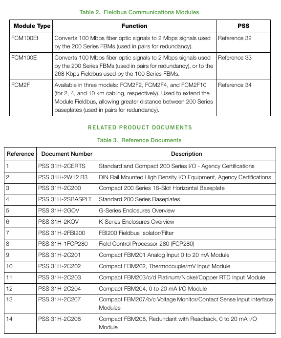
Control processor FCP280 200/100 Series FBMs control interface, supporting 4 HDLC buses and up to 128 FBMs
FCP270 is compatible with dual baud rates (2Mbps/268Kbps) and requires FBI100 to adapt to 100 Series. It supports 32 200 Series FBMs without FEM100
ZCP270 is compatible with 100 Series racks and supports up to 128 FBMs per module through FCMs communication
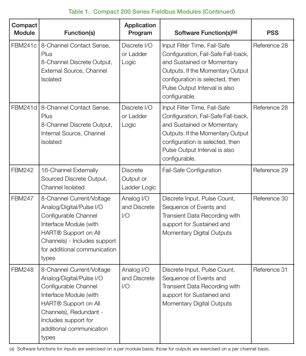
Fieldbus Modules (FBMs) Analog Input Class FBM201 (0-20mA), FBM214b (HART) ® Input channel isolation/differential isolation, 8-32 channels
Analog output class FBM215 (HART) ® Output), FBM237 (redundant 0-20mA) and other fail safe configurations (hold/fallback), 4-8 channels
Discrete I/O class FBM217 (32 channel input), FBM219 (24DI+8DO) and other group isolation/channel isolation, 8-32 channels
Hybrid I/O classes such as FBM227 (analog+discrete) and FBM247 (current/voltage/pulse) support HART ®、 Multi signal type adaptation
Auxiliary component base plate 16 slot horizontal base plate (RH101AA) supports 16 FBMs, DIN rail/19 inch rack installation
Communication module FCM100E/Et (fiber to bus conversion), FCM2F (fiber extension) FCM2F supports up to 10km single-mode fiber
Isolator FBI200 extends bus distance to 305m, isolation filtering
Shell G/K series G13/G14 (system/terminal shell), K13/K14 IP43/54 protection, suitable for ordinary/harsh environments
Key technical characteristics and advantages
performance
The analog input adopts SigmaDelta fast integration ADC, with an update speed of up to 25ms, suitable for high-speed regulation and control
Built in configurable moving average filter effectively removes electromagnetic noise
System communication speed: 100Mbps Ethernet (control network), 2Mbps/268Kbps HDLC module bus
Reliability Design
Integrating logic functions into a single ASIC chip reduces the number, volume, heat dissipation, and cost of components
Single module availability 0.999974 (redundant power supply+2-hour MTTR), redundant module availability 0.9999964
Optional redundancy: power supply, control network FCMs、 Control processors, module bus cables, and some FBMs
Deployment flexibility
Compact size: 1 16 slot compact base plate+16 FBMs space<2 standard 200 Series base plates+16 standard FBMs
Installation method: Horizontal DIN rail installation or 19 inch rack installation, supporting distributed small cabinet deployment
Cable length: shielded twisted pair 0.12-60m, fiber optic extension up to 20km (2 pairs of FCM2F10)
environmental adaptability
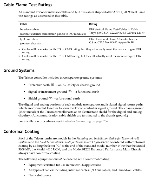
Pollution protection: Class G3 (ISA S71.04), suitable for harsh industrial pollution environments
Working temperature: FBMs up to 60 ℃ (140 ° F)
Safety certifications: UL (US Canada), ATEX (Explosion proof), CE (Low Voltage/EMC/ATEX Directive), RoHS compliance
System configuration and upgrade requirements
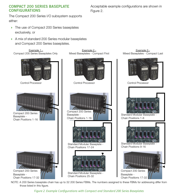
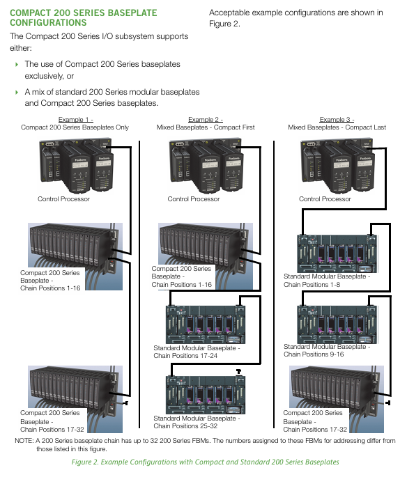
configuration scheme
Pure compact chassis configuration: only using Compact 200 Series chassis
Mixed configuration: Compact mixed with standard 200 Series baseboard (supports compact in front/back)
Maximum scale: Up to 32 FBMs per single bottom chain, 4 bottom chains supported per FCP280
Upgrade requirements
Space requirement: The installation location should have sufficient horizontal DIN rails
Power Requirements: Supports FPS480-24/FPS400-24/FPS220-24/FPS120-24 power supplies
Cooling requirement: 1 fan tray is required for every 2 adjacent compact baseboards (1 for each baseboard when deployed separately)
Cable replacement: The terminal cable of the standard 200 Series FBMs needs to be replaced with a Compact series adapter cable
Electrical and safety regulations
Grounding requirements: comply with IEC 61000-5-1/5-2 standard (or regional equivalent standard)
Power configuration: 24V DC power supply, supports single/redundant power distribution, triggers icon color change, system alarm, and print notification in case of power failure
Isolation level: FBMs support channel isolation, differential isolation, and group isolation, with some terminal components (TA) providing additional channel isolation
Wiring characteristics: FBMs are hot swappable and do not affect external field device wiring and internal cable connections
Key questions and answers
Question 1: What are the core advantages of the Compact 200 Series I/O subsystem? What scenarios are applicable?
Answer: The core advantages are concentrated in three points: ① High reliability and availability, achieved through ASIC integrated design with high availability of single module 0.999974 and redundant module 0.9999964, suitable for continuous operation requirements; ② Flexible deployment and compact design, with a volume only half of the standard 200 Series, supporting distributed DIN rail/rack installation, reducing wiring costs; ③ Strong environmental adaptability and compatibility, Class G3 pollution protection, 60 ℃ high temperature tolerance, and compatibility with existing 100/200 Series I/O devices, supporting seamless system upgrades. Applicable scenarios include: continuous/batch/discrete control tasks in industrial sites, harsh polluted environments (such as chemical and metallurgical industries), large factories that require remote distributed deployment, and existing I/A Series ® System upgrade project.
Question 2: What are the core components of this subsystem? What are the differences in the carrying capacity of FBMs with different control processors?
Answer: The core components include: ① Control processor (FCP280/FCP270/ZCP270); ② 20+FBMs (analog/digital/hybrid I/O types); ③ 16 slot horizontal bottom plate, FBI200 isolator, FCM communication module; ④ G/K series protective casing and terminal components (TA). The differences in the carrying capacity of FBMs among different processors are as follows:
FCP280: Supports up to 128 200 Series FBMs, or 128 (100+200 Series) hybrid FBMs (up to 64 for 100 Series);
FCP270: Up to 32 200 Series FBMs without FEM100, up to 128 with FEM100, and up to 64 with 100 Series;
ZCP270: Supports up to 128 FBMs (100/200 Series) through FCM100E, with a single FCM100Et pair supporting 32 FBMs.
Question 3: What are the components of the system’s redundant configuration? What is the cable length limit during deployment?
Answer: ① Redundant configuration coverage: power supply, control network, FCMs (communication modules), control processors, module bus cables, and some FBMs (such as FBM216b/FBM218); Redundant design can avoid single point failures and ensure the continuous operation of critical process circuits. ② Cable length limit:
Shielded twisted pair cable (module bus/backplane interconnection): 0.12-60m (single segment), total length of the entire 2Mbps HDLC bus ≤ 60m (including FBI200 connection);
Fiber optic cables (FCM2F series): FCM2F2 (2km), FCM2F4 (4km), FCM2F10 (10km), 2 pairs of FCM2F10 can be extended up to 20km;
Terminal Assembly (TA) and Base Plate Connection Cable: 0.5-30m.
Product positioning: Tricon v9-v11 is a high tolerance error controller under Schneider Electric, designed specifically for safety critical applications. Its core advantage is fault tolerance, which can maintain error free control in the event of component hard or transient faults.
Core architecture: Triple Modular Redundancy (TMR) is adopted, with three independent channels executing control programs in parallel. Digital inputs and outputs are subject to majority voting through hardware/software mechanisms, while analog inputs are selected using median selection to ensure data integrity.
Key features: Supports online installation and maintenance, remote I/O expansion (up to 12 kilometers through SRXM module), enhanced diagnostic monitoring, and multi protocol communication interconnection.
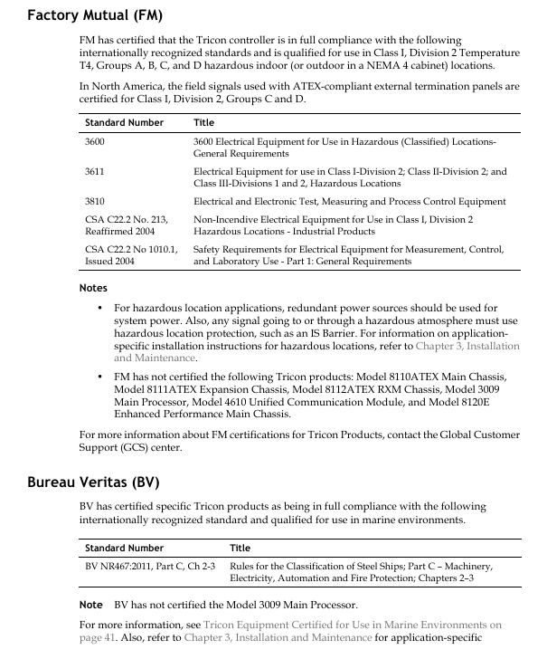
International certification: Passed multiple certifications such as CSA in Canada, FM in the United States, T Ü V Rheinland in Germany, and the Nuclear Regulatory Commission (NRC) in the United States, and meets standards such as IEC 61508 (SIL 1-3) and ATEX Zone 2.
The main chassis 8110 (supporting 6 sets of I/O modules) and 8120E (enhanced, supporting UCM modules) accommodate the main processor, power module, and provide I/O expansion bus
Expansion chassis 8111 (8 sets of I/O modules), 8121 (low density, supporting HART modules) to expand I/O capacity, with a distance of ≤ 30 meters from the main chassis
Remote chassis RXM 8112 supports remote I/O expansion, up to 12 kilometers away
Main processors (MP) 3006/3007 (v9.0-9.5), 3008 (v9.6-10. x), 3009 (v11. x) execute control programs, manage I/O and communication, TriBus speed up to 1000 Mbps
The power module 8310 (120 VAC/DC), 8311 (24 VDC), and 8312 (230 VAC) are designed with dual redundancy. A single module can support the entire chassis load and output 6.5 VDC
The I/O module supports analog input (3700A/3703E), digital output (3604E/3625), thermocouple input (3708E), and supports analog input (0-10 VDC/4-20 mA), digital input (24-115 VAC/DC), pulse signal acquisition and output
Communication modules TCM (supporting Ethernet/Modbus), UCM (compatible with Foxboro Evo), and HART modules (2770H/2870H) enable communication with DCS systems and external devices, and support OPC and GPS time synchronization
Working principle and fault-tolerant mechanism
Redundant workflow: Three main processor channels independently execute control programs, synchronize data through TriBus, perform “2/3 voting” on digital input and output, and take the median of analog input to ensure that faulty channel data does not affect the final result.
Fault tolerance: When a single channel hardware fails, the other two channels automatically take over the function, and the faulty module can be replaced online without interrupting the controlled process; The power module and communication link both support redundant configuration.
Data processing: The input module microprocessor filters signals and diagnoses faults, the output module verifies output status and diagnoses wiring issues, and the main processor achieves data synchronization and error correction through TriBus.
Core functions and technical specifications
Hardware scalability
Chassis extension: up to 15, main chassis+extension chassis+remote chassis combination
I/O Capacity: Analog input/output up to 1024/512 points, digital input/output up to 2048 points, pulse input up to 80 points
Remote Expansion: Supports remote I/O connections up to 12 kilometers through RXM/SRXM modules
Interconnected systems: Foxboro I/A Series/Evo, Honeywell TDC-3000/UCN and other DCS
Communication speed: TriBus (4-1000 Mbps), I/O bus (375 Kbps), Ethernet (10/100 Mbps)
Diagnosis and maintenance
Diagnostic tool: EnDM software integration, real-time monitoring of hardware status, communication links, and program operation
Status indication: Each module is equipped with PASS/AULT/CTIVE indicator lights, supporting fault location
Online maintenance: The module is hot swappable and can be replaced without interrupting the on-site I/O signal
environmental adaptability
Working temperature: 0-60 ℃, storage temperature: -40-75 ℃
Humidity: 5% -95% (without condensation)
Corrosion grade: Class G3 (compliant with ISA S71.04 standard)
Vibration shock: 1 G (8.4-150 Hz), 15 G (6-11 ms)
Applicable scenarios and authentication
Typical Applications
Safety Instrumented System (SIS): Emergency Shutdown Interlock for Chemical and Petroleum Refining
Nuclear power applications: 1E level nuclear safety related controls
Marine environment: Ship automation certified by BV classification society
Other: Fire gas detection, semiconductor manufacturing safety control
Key certification
Electrical safety: CSA C22.2 No. 61010-1, UL 61010-1
Functional safety: T Ü V Rheinland IEC 61508 (SIL 1-3)
Hazardous environment: ATEX Zone 2, Class I Division 2
Nuclear Power Certification: NRC 1E Application Certification
Key issue
Question 1: What is the core redundancy mechanism of the Tricon v9-v11 system? How to ensure fault tolerance?
Answer: The core adopts a Triple Modular Redundancy (TMR) architecture, with three independent channels executing control programs in parallel. Input and output are processed through a hardware voting mechanism – digital quantities use “2/3 majority voting”, and analog quantities use “median selection”; When a single channel fails, the other two channels automatically take over the function, and the faulty module can be replaced online without interrupting the controlled process. The power module and communication link support redundant configuration to ensure that the system has no single point of failure.
Question 2: What key hardware extensions does the Tricon v9-v11 system support? What is the maximum configuration limit?
Answer: Hardware expansion includes chassis expansion (main chassis/expansion chassis/RXM remote chassis), I/O module expansion (analog/digital/pulse/thermocouple, etc.), communication module expansion (TCM/UCM/ACM, etc.), and remote I/O expansion (up to 12 kilometers through SRXM module); The maximum configuration limit is 15 chassis and 118 I/O modules, supporting up to 2048 digital input/output points, 1024 analog input points, and 512 analog output points.
Question 3: What are the applicable scenarios and core certifications for the Tricon v9-v11 system?
Answer: Suitable for safety critical scenarios such as chemical safety instrumented systems (SIS), petroleum refining process control, nuclear power 1E level applications, marine automation, and fire gas detection; Core certifications include electrical safety (CSA, UL), functional safety (T Ü V Rheinland IEC 61508 SIL 1-3), hazardous environments (ATEX Zone 2), nuclear power certification (NRC), marine certification (BV), etc., meeting compliance requirements for industrial applications in multiple global locations.
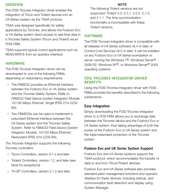
Product Name Foxboro Evo FDSI Triconex Integrated Driver
Brand Foxboro (formerly Invensys, under Schneider Electric)
Document version PSS 31S-3A9 B3
The core positioning is an integrated driver based on the TSAA protocol, which enables data exchange and unified management between the Triconex security controller and the Foxboro system
The core protocol Triconex System Access Application (TSAA) protocol is designed specifically for secure applications
Bidirectional data read and write: Supports real-time data exchange between Foxboro system and Triconex controller, including input and output of analog (integer/IEEE single precision floating-point) and digital quantities.
Efficient access method: The I/O points of the Triconex controller can be directly accessed through the TriStation tag name or Modbus alias without additional adaptation.
Batch operation support: A single write command can achieve multi-point writing, improving data transmission efficiency.
System Function Reuse: Directly supports the standard factory management functions (such as startup and fault detection) and operator display interface of Foxboro Evo/I/A Series, without the need for separate development.
(2) Redundancy and reliability design
Redundant configuration: FBM233 dual modules can form a redundant architecture, which is divided into a master module and a tracker module. The modules monitor the health status and share device information through communication links.
Fault switching: When the main module fails, it automatically switches to the tracking module without data loss during the switching process, and can also be manually triggered through System Manager.
Fault maintenance: When FBM or network faults occur, replacing modules or repairing the network will not affect the normal transmission of on-site I/O signals.
(3) Diagnostic and monitoring capabilities
Enhanced Diagnostic Monitoring (EnDM): Supports the integration of Triconex Enhanced Diagnostic Monitor software, which can be directly launched from Foxboro System Manager to monitor the hardware, communication, and application status of the Triconex controller.
Diagnostic data output: All diagnostic data of Triconex devices are provided through DCI input blocks, which can quickly develop FoxView process graphics to display diagnostic information and status.
Connection detection: System Monitor can detect the real-time connection status of devices. When a device fails, the FDSI ECB201 object will enter a warning state and trigger a system alarm.
(4) SOE event logging function
Event Collection: Sequence of Events (SOE) messages generated by the Triconex system can be collected and recorded to the AIM * Historian or Alarm Provider application through the Aprint mechanism.
Configuration management: SOE configuration information (device IP, event destination, alarm block, time zone, SOE point list) is stored in an XML file, independent of the control application configuration.
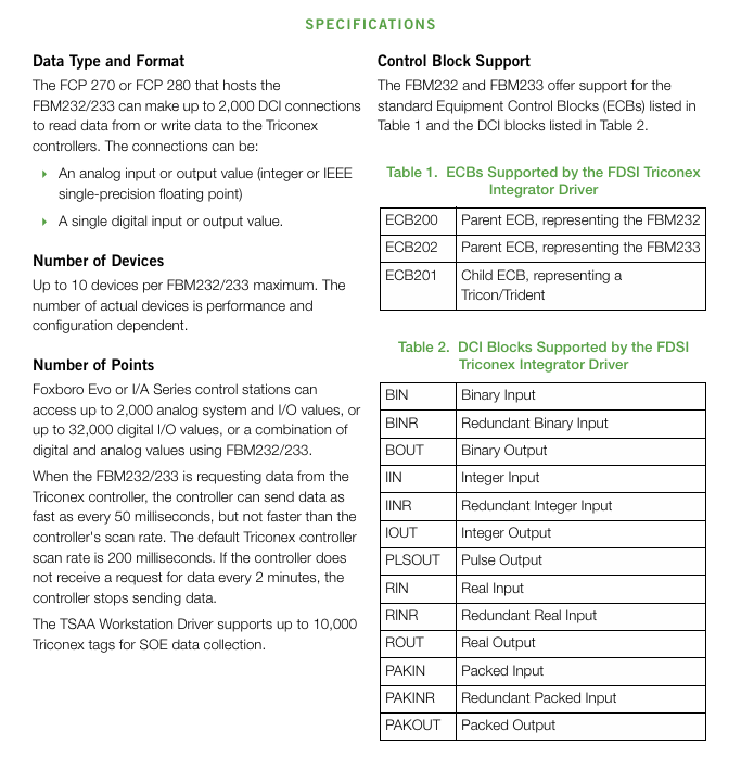
Capacity support: The TSAA workstation driver supports up to 10000 Triconex tags for SOE data collection.
Software and hardware compatibility and requirements
Diagnostic software Triconex EnDM v2.8.0+(requires System Manager v2.5+for direct startup)
Key technical parameters
Parameter category specific specifications
Single FBM supports up to 10 Triconex devices (actual quantity depends on performance and configuration)
DCI connection capacity up to 2000 (used for reading and writing Triconex controller data)
Data point capacity of up to 32000 digital I/O points, or up to 2000 analog systems/I/O values (can be mixed configured)
The fastest data scanning rate is 50 milliseconds per time (not exceeding the Triconex controller’s own scanning rate, default is 200 milliseconds per time)
Communication timeout setting: If the controller does not receive a data request for 2 minutes, it will stop sending data
Support control block ECB block (ECB200/FBM232, ECB202/FBM233, ECB201/Triconex devices); DCI block (13 types including BIN, BOUT, IIN, IOUT, etc., including redundancy types)
Supports 13 core commands of TSAA (such as data request/response, clock read/write/adjust, SOE data request, etc.)
Installation and Configuration
Installation feature: Driver installation does not require shutting down system software or restarting workstations/servers; When updating the driver, it can be directly downloaded to FBM232/FBM233 without affecting the operation of other parts of the Foxboro system.
Configuration tool:
Driver configuration: Use FDSI Configurator (to be installed on a compatible workstation/server);
Device configuration: Use the TriStation Configurator to configure the Triconex controller;
SOE configuration: Maintain SOE point and device configuration information through XML files, independent of control applications.
Network configuration:
The Triconex controller needs to be connected to the FBM through a primary/backup hub/switch;
The Trident V3.0 CIM module only supports switches and does not support hubs.
Key issues
Question 1: What is the core integration value of FDSI Triconex Integrated Driver? How to achieve efficient interconnection between Triconex safety controller and Foxboro system?
Answer: The core integration value lies in the deep integration of Triconex security system and Foxboro automation system without the need for separate interface development. It directly reuses the factory management functions, operating interface, and diagnostic tools of Foxboro system, reducing integration costs and improving system consistency. Efficient interconnection implementation method: ① Based on the TSAA protocol designed by Triconex for secure applications, establish a 10/100 Mbps Ethernet connection through FBM232 (single module) or FBM233 (redundant module); ② Support direct access to device I/O points using TriStation tag names or Modbus aliases, and enable multi-point writing with a single command; ③ Driver installation and updates do not require downtime, the configuration process is simple, and a single FBM can connect up to 10 Triconex devices, meeting the integration requirements of medium and large-scale projects.
Question 2: What are the redundant configuration and fault handling designs of this driver? How to ensure the reliability of data transmission?
Answer: Redundancy and fault handling design: ① Hardware redundancy: FBM233 dual modules are used to form a master-slave architecture, with real-time monitoring of health status and sharing of device information between modules; ② Fault switching: When the main module fails, it automatically switches to the tracking module without data loss, and also supports manual switching; ③ Maintenance convenience: In case of FBM or network failure, replacing modules or repairing the network will not affect on-site I/O signals. Data transmission reliability guarantee: ① Communication link redundancy: Build dual links through primary/backup hubs/switches; ② Data scanning mechanism: a scanning rate of up to 50 milliseconds per scan (adapted to controller capabilities) to ensure real-time performance; ③ Timeout protection: If the controller does not receive a request within 2 minutes, it will stop sending to avoid invalid transmission; ④ Diagnostic warning: System Monitor detects connection status in real-time, DCI block outputs diagnostic data, EnDM tool monitors equipment status, and detects potential faults in advance.
Question 3: What Triconex controller models and system environments does the driver support? How can data processing capabilities match project requirements of different scales?
Answer: Compatibility between controller and system environment: ① Supported Triconex controllers: Tricon v9.7. x and above, Trident v1.2 and above (excluding v2.0-2.1.1), Tri GP v2.1.2 and above; ② Compatible Foxboro systems: I/A Series v8.4 and above, Control Core Services v9.0 and above; ③ Supported operating systems: Windows XP/7/Server 2003/2008 R2. Data processing capability adaptation: ① Equipment capacity: A single FBM can support up to 10 Triconex devices, which can be expanded through multiple FBMs; ② Data point capacity: Supports up to 32000 digital I/O points or 2000 analog values, meeting the signal acquisition needs of small (single device) to medium to large (multi device cluster) projects; ③ Connection capacity: 2000 DCI connections can cover the data exchange needs of multiple devices, SOE logs support the collection of 10000 tags, and are suitable for high demand security event tracing scenarios.
EcoStruxure Foxboro DCS Control Editors is a professional configuration and development tool launched by Schneider Electric for Foxboro distributed control systems (DCS). Its core positioning is to provide full lifecycle control strategy design, editing, configuration, deployment, and operation support for industrial automation projects. Relying on the AVEVA intuitive user interface and Microsoft Visio rendering engine, complex control logic is transformed into visual operations, greatly reducing engineering difficulty and improving configuration quality and efficiency.
The core value of this tool lies in breaking the limitations of traditional DCS configuration and achieving integrated management from strategy design to deployment and operation: on the one hand, it supports multi scenario adaptation, which can not only meet the initial engineering design of new projects, but also support the expansion and technological upgrading of existing systems; On the other hand, through standardization, templating, and automation functions, it reduces repetitive labor, ensures consistency and reliability of control logic, and has strong compatibility and scalability to meet the control needs of different scale industrial scenarios.
Core concepts and architecture system
Before using Control Editors for configuration, it is necessary to clarify its core concepts and architectural hierarchy to ensure the standardization of policy design and system deployment
(1) Core level definition
Control Station: The hardware platform core responsible for executing the adjustment, sequence, logic, and supervisory control strategies assigned to it. It is the physical carrier for the operation of control strategies.
Compound: The top-level logical unit that needs to be bound to a specific control station and contains multiple user designed control policies. It is the intermediate layer of association between policies and hardware.
Control Strategy: A functional reusable control entity composed of multiple control blocks and internal sub strategies, which can be instantiated as specific control circuits and other control units.
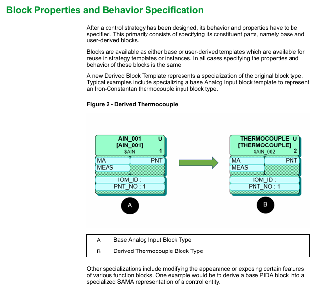
Control Block: The most basic control element, corresponding to specific control functions (such as signal acquisition, logic operation, regulation control, etc.). Foxboro DCS supports over 100 different types of control blocks, divided into two categories: basic templates and user derived templates.
(2) Architectural design features
Modular architecture: All control logic is based on “blocks” and “strategies” as basic modules, supporting free combination, reuse, and expansion. The control system can be flexibly built according to project requirements.
Hierarchical deployment logic: Following the hierarchical allocation mechanism of “policy → composite object → control station”, ensuring precise matching between control logic and hardware resources, facilitating system management and maintenance.
Open compatibility architecture: supports integration with ArchestrA industrial application servers, third-party systems, and various fieldbus devices, follows standardized communication protocols, and ensures system interconnectivity.
Core functions and operational features
(1) Control Strategy Design and Editing
Graphic visualization design: The strategy editor provides a visual canvas, where users can drag and drop basic control blocks or derived templates onto the canvas, connect exposed parameters of the blocks through lines, and quickly build control logic. Support user-defined rendering styles for policy components, including Scientific Apparatus Makers Association (SAMA) standard symbols, to meet industry standards.
Flexible configuration of control blocks:
Basic control block: covering core functions such as signal input, logical operation, and regulation control, and can directly call configuration;
Derivative control block: Users can customize based on the basic block, such as deriving the basic analog input block (AIN) into an iron constantan thermocouple input block, or modifying the appearance and functional exposure of the PIDA block to generate control entities that comply with SAMA standards.
Programmable logic support: For complex control scenarios, multiple types of programmable blocks and exclusive editors are provided:
Text editor: used for High Level Batch Language (HLBL) programming, adapted to batch control scenarios;
Graphic Editor: Supports Sequential Function Charts (FoxSFC) and Ladder Logic Diagram (LLD) programming, visually presenting sequential control and logic control processes;
Universal computing blocks: including MATH, LOGIC, Calc, CalcA and other calculator blocks, to meet various mathematical operations and logical judgment needs.
(2) Data interaction and debugging optimization
Multi dimensional data interface:
Report interface: Supports exporting configuration data from Microsoft SQL Server and Excel for easy data archiving and analysis;
Editing interface: Provides an intuitive Excel interface that allows for direct editing of configuration parameters in Excel, improving batch editing efficiency.
Real time debugging capability: Control strategy drawings can overlay and display real-time updated parameter values, allowing for intuitive observation of control logic operation status without relying on human-machine interface (HMI); Support uploading real-time data from the controller directly to the database, or downloading configurable parameters from the database to the controller, without the need for a complete deployment process, greatly reducing the debugging cycle.
(3) Batch operation and migration upgrade
Batch generation strategy: Supports batch generation of control strategies based on predefined templates and external project data (such as Excel, CSV, SaveAll, IACC Export, SysDef Export, or proprietary XML documents). Users can use Visual Basic scripts to perform targeted editing on imported data grids, such as batch modifying policy parameters and adjusting composite object assignments, to quickly complete large-scale project configurations.
System migration compatibility: Provides the ability to batch migrate control strategies from installed I/A Series systems and Foxboro DCS, seamlessly migrating the control logic and intellectual property of existing systems to new systems, protecting users’ existing investments, and reducing upgrade costs.
Import and export function: Supports the import and export of control strategy design files, facilitating cross project reuse, backup, and sharing, and improving engineering efficiency.
(4) System and equipment configuration
System topology construction: Users can instantiated hardware units such as control stations and fieldbus modules (FBMs) and customize their names. These hardware units can be allocated to designated factory unit areas (such as centrifuge area, purification area, reaction area, solvent recovery area, storage tank area, etc.) through a network view, visually presenting the system hardware layout and ownership relationships.
Intelligent device lifecycle management: supports comprehensive management of digital field devices using FOUNDATION Fieldbus, HART, and PROFIBUS technologies, including device access, parameter configuration, operation monitoring, fault diagnosis, debugging, and troubleshooting, ensuring stable linkage between field devices and DCS systems.
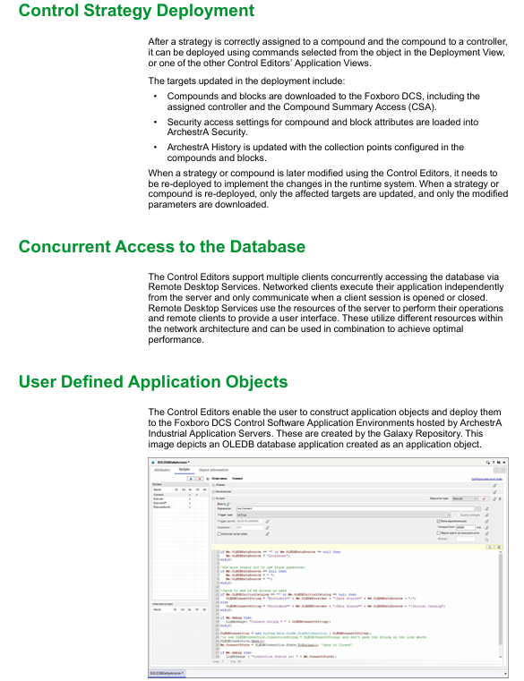
ArchestrA platform deployment: ArchestrA IAS platform, engine, and application objects (such as OLEDB database applications) can be created and deployed to the Foxboro DCS control software application environment to expand the system’s functional boundaries.
(5) Security and Collaboration Management
Role based permission control: ArchestrA’s role-based security model is adopted, where users subscribe to corresponding roles based on job responsibilities, and roles are associated with specific access permissions (such as operations, secure writes, configuration modifications, etc.) and security groups (corresponding to factory areas). Supports three authentication methods: local authentication, host operating system binding authentication, and Microsoft Active Directory authentication (it is recommended to configure at least two redundant domain controllers to enhance security).
Change Tracking and Traceability: Deeply integrated with Foxboro DCS’ System Advisor change tracking function and FoxCTS change tracking software, all control configuration modifications (such as parameter adjustments) and program changes (such as HLBL, FoxSFC, LLD program modifications) will be recorded and synchronized to associated software, meeting industry regulatory requirements and facilitating fault tracing and auditing.
Multi client concurrent access: The server supports multiple clients to access the configuration database simultaneously through remote desktop services, with a record locking mechanism to prevent concurrent operation conflicts. The client runs independently and only communicates with the server when the session is open or closed, fully utilizing network resources and ensuring smooth operation.
Deployment process and operation mechanism
(1) Deploy core processes
Strategy design and configuration: Complete the graphical design, parameter configuration, and logical correlation of control strategies;
Hierarchical allocation: Assign control strategies to composite objects, and then bind the composite objects to the target control station;
Deployment execution: Select the corresponding object through the deployment view, execute the deployment command, and the system automatically completes the following operations:
Download the composite object and control block to the designated control station and Compound Summary Access (CSA);
Load the security access settings of the composite object and control block into the ArchestrA security system;
Update ArchestrA historical database and synchronize the configured collection point information;
Change deployment: After modifying the strategy or composite object, it is necessary to redeploy. The system only updates the affected targets and modified parameters to avoid resource consumption and downtime risks caused by full deployment.
(2) Operation guarantee mechanism
Resource isolation: Client and server resources are isolated, with the client only providing an operating interface and core computing relying on server resources to ensure operational stability;
Fault tolerance: Supports redundant configuration of critical hardware, combined with change tracking and fault diagnosis functions, to quickly locate and handle operational anomalies;
Real time synchronization: Configure data and run data to be synchronized in real-time, ensuring that modified parameters take effect in a timely manner and guaranteeing the accuracy of control logic.
Software and hardware specification requirements
(1) Minimum configuration requirements
Device/Role Memory (RAM) Hard Disk Capacity Special Instructions
Remote desktop services require a minimum of 16GB, with a recommended minimum of 32GB and 150GB for controlling HMI. Virtual machines based on remote desktop services require additional reserved space, with each user requiring 3GB of C drive space for managing applications
Control software Galaxy minimum 16GB, recommended 32GB minimum 250GB for storing system configuration and policy data
The control software Historian has a minimum of 16GB, with a recommended minimum of 32GB and 500GB for storing historical operational data, which needs to be expanded according to the data volume
All other roles require a minimum of 16GB, with a recommended minimum of 32GB and 150GB, covering regular clients, configured workstations, etc
(2) System and hardware compatibility
Operating System: Supports Windows Server IoT 2022 or Microsoft Windows 10 IoT Enterprise LTSC 2021 (64 bit version);
Computer hardware: Hardware devices that require Foxboro DCS certification, such as D96, H90, H92, H94, V91, V95, etc;
Communication network: Require 100 Mbps TCP/IP switched Ethernet to ensure stability and real-time data transmission.
Product advantages and applicable scenarios
(1) Core advantages
Engineering efficiency improvement: Through graphic design, template reuse, batch operation and other functions, the initial design and expansion transformation cycle of the project is significantly shortened, reducing repetitive labor;
Configuration quality assurance: standardized design process, role-based permission control, and change tracking function to ensure consistency, security, and traceability of control logic;
Strong system compatibility: Supports migration from legacy systems (I/A Series, old Foxboro DCS), compatible with multiple fieldbus devices and third-party systems, reducing system upgrade and integration costs;
Full lifecycle support: covering the entire process of project design, deployment, debugging, operation, and upgrade, providing one-stop configuration and management tools to adapt to the needs of different stages of the project.
(2) Applicable scenarios
New industrial automation projects: suitable for new projects in industries such as chemical, power, pharmaceutical, petroleum, etc., quickly build Foxboro DCS control system;
Existing system upgrade and renovation: Provide a technical upgrade path for existing users of Foxboro DCS to achieve smooth migration of control logic and functional expansion;
Large scale project expansion: supports batch generation and configuration strategies, adapting to the control requirements of large factories or cross regional projects;
Multi project reuse scenario: The control strategy and intellectual property of one project can be transferred to other projects, and the new scenario can be adapted through editing tools to improve the efficiency of multi project implementation.
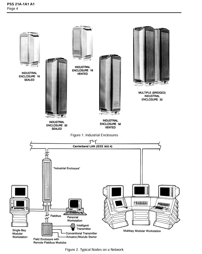
Product Name Foxboro I/A Series Industrial Automation System
Belonging to Foxboro (a brand under Invensys)
Core positioning: The world’s first open industrial system, an automation control solution for industrial manufacturing processes
The core architecture concept is to build modules with “nodes” as the core, achieving flexible deployment and expansion
Key certifications and standards follow international/industrial standards such as ISO, IEEE, Factory Mutual, EEC, ISA, ISO9001, etc
More than 100 types of smart factory equipment have been integrated
Core advantages
(1) Open and compatible architecture with strong adaptability
Wide scale adaptation: Supports small systems that handle local devices, as well as large complex systems distributed across local and wide area networks, covering diverse application scenarios.
Flexible combination of modules: hardware and software modules can be freely matched, and system functions can be customized according to application requirements and installation locations, without being limited by fixed configurations.
Truly distributed deployment: Implementing a dual distributed design at both the functional and physical levels, where each node operates independently and can collaborate with the network, enhancing system stability and response efficiency.
Open compatibility features:
Adhere to OSI communication standard model, IEEE 802.4 and other network standards, do not rely on proprietary communication networks, and support integration with third-party devices/systems;
Having backward compatibility to protect users’ existing investments in system integration and applications;
Support third-party application access and provide unlimited functional flexibility for expansion.
(2) Modular design, reducing the whole life cycle cost
Easy installation and maintenance: The hardware module adopts a sturdy packaging design, which can withstand the harsh conditions of industrial environments (environmental, electrical, physical aspects); The module has intelligent self checking function, which automatically detects each other after being connected to the system. When there is a fault, the problem is accurately located through color coded indicator lights and messages.
Quick replacement and upgrade: After replacing the faulty module, the system will automatically download the adaptation software without the need for complex configuration; Small systems can gradually expand into integrated automation and information systems at the factory level, adapting to business growth and budget planning.
The total cost is controllable: the entire process cost from installation, training, operation to maintenance is relatively low, modular design reduces redundant investment, rapid fault repair reduces downtime losses.
(3) High reliability, ensuring continuous operation
Fault tolerance capability: Key functions can add redundant hardware modules (including LAN/WAN communication redundancy), which are completely transparent to software and enable instantaneous switching, enhancing the system’s ability to withstand faults.
Network fault detection: equipped with network fault detection function, further enhancing system reliability and fault diagnosis efficiency, reducing downtime.
(4) User friendly operation and excellent interactive experience
Adopting high-quality, high-resolution graphical interface and multi window design, the operating interface is unified, safe, and friendly;
The 50 series workstation enhances graphics and window functions, supports concurrent access to multiple applications, and improves operational efficiency;
Interactive elements such as menus and graphics can be configured according to the needs of operators to adapt to different job scenarios.
System architecture and core modules
(1) Core architecture: centered around “nodes”
Nodes are the basic building units of a system, capable of independent operation and execution of automation related functions, and can also connect to other Foxboro or non Foxboro nodes through compatible networks.
A typical node typically consists of a set of book sized modules, workstations, and field devices inside an industrial chassis. The modules are interconnected through Nodebus (a robust serial bus) and can be connected to peripheral devices or other modules through various communication links.
(2) Core module type
1. Processor modules (four major categories)
Module Type Core Function Connection Device/Network
Application processors for historical data collection and archiving, database management, coordination with other processor modules (such as distributed batch control systems), high-capacity storage devices, information networks (such as Ethernet, supporting bidirectional information transmission)
Workstation processors provide interface support, receive and display X Window display CRT, keyboard, alarm keyboard, and other workstation devices and information networks (such as Ethernet) from other computers
Communications processors/interfaces/gateways enable cross device/cross network communication adaptation to RS232/485 devices, local area networks (LAN), wide area networks (WAN), SPECTRUM, and other networks
Control processors execute control logic (such as ladder logic, regulating control, sequential control) for I/A Series fieldbus modules and devices
2. Fieldbus Module
Core function: Connect traditional sensors, actuators, and I/A Series intelligent field devices, serving as a communication bridge between field devices and control processors.
(3) Network and Communication
Communication foundation: Following the Open Systems Interconnection (OSI) standard model and adopting communication standards specified by ISO and IEEE;
Network type: Nodes communicate through a single level or layered IEEE 802.4 network, rather than a proprietary network;
Supporting protocols/networks: TCP/IP, DECnet, NFS and other information network protocols, as well as fieldbus (supporting communication between control processors and remote fieldbus modules/devices).
System scale and deployment form
System scale deployment form, core components
Small system independent personal workstation or single node personal workstation, or single node with a small number of modules
Large scale system multi node distributed deployment with multiple nodes connected via IEEE 802.4 compatible carrier band LAN, enabling geographic distributed deployment of instrument equipment and functions through fieldbus
Modular expansion gradually expands from small-scale systems, gradually adding modules and nodes according to production needs and budgets, and upgrading to a factory level integrated system
Key issues
Question 1: What are the core architectural advantages of Foxboro I/A Series system? How to support its positioning as an “open industrial system”?
Answer: The advantages of core architecture are reflected in three aspects: modular design with “nodes” as the core, open features that follow international standards, and truly distributed deployment. The key to supporting the positioning of “open industrial systems” is to comply with international standards such as ISO, IEEE, OSI, etc., adopt non proprietary communication networks (IEEE 802.4), and seamlessly integrate with third-party devices/systems; Secondly, it supports flexible mixing of hardware and software modules, adapting to diverse scenarios ranging from small to large distributed systems; The third is to have backward compatibility, protect existing investments, and support third-party application access. It can integrate over 100 types of smart factory equipment and continue to expand with technological development.
Question 2: What are the key designs of Foxboro I/A Series system in terms of reliability and operational convenience?
Answer: Reliability design: ① The module adopts sturdy packaging and can withstand harsh industrial environments; ② Equipped with module self detection function, it can accurately locate faults through color coded indicator lights and messages; ③ Redundant hardware configuration that supports critical functions, with hardware redundancy completely transparent to software and instantaneous switching completion; ④ Equipped with network fault detection function to improve the efficiency of fault diagnosis. Convenient operation and maintenance design: ① Modular design, easy installation and replacement, automatic download of adaptation software after replacing faulty modules; ② The system can be modularized and gradually expanded without the need for a one-time large-scale investment; ③ The user interface is unified and friendly, supporting multi window and menu based configuration, reducing training costs.
Question 3: What are the types of processor modules in the Foxboro I/A Series system? What are their respective core functions and connection objects?
Answer: Processor modules are divided into four categories, as follows:
Module Type Core Function Connection Object
Application processor historical data collection and archiving, database management, coordination with other processor modules, high-capacity storage devices, Ethernet and other information networks
The workstation processor provides interface support, displays cross device X Window CRT, keyboard, alarm keyboard and other workstation devices, Ethernet and other information networks
Communication processors/interfaces/gateways enable cross device and cross network communication adaptation to RS232/485 devices, LAN/WAN, SPECTRUM, and other networks
Control processor executes control functions such as ladder logic, adjustment control, sequence control, etc. I/A Series fieldbus modules and equipment
Product positioning: A new generation DGA (Dissolved Gas Analysis) monitoring solution that has been validated on-site
Core mission: Monitor the gas and moisture content in transformer insulation oil, warn of faults, extend equipment life, and reduce unplanned shutdowns
With 40 years of experience in online DGA solutions, we have sold over 50000 units worldwide
Warranty and 7-year product warranty; The sensor has a lifespan of over 10 years (based on accelerated aging testing, MTTF is 11.5 years)
Core advantages
Wide adaptability: supports mineral insulating oil, natural and synthetic ester insulating oil transformers
Low maintenance and convenience: miniaturized design, no moving parts; Can be installed through existing transformer valves, usually without the need for shutdown
Functional scalability:
Sensor options: Traditional composite gas sensors (H ₂, CO, C ₂ H ₄) or single H ₂ sensor (mineral oil only)
Scalable monitoring: Connect sensors to monitor top oil temperature and load current, support IEEE transformer model calculation (such as winding hotspot temperature)
On site upgrade: can add analog signal input to monitor more key parameters
Powerful Integration: Supports multiple communication methods and protocols, seamlessly integrates with GE Perception ™、 PREDIX ™ Waiting for digital platforms and SCADA systems
Intuitive operating experience: Built in backlit LCD display (128 × 64 pixels) and keyboard, supporting local data visualization and device configuration
Key technical parameters
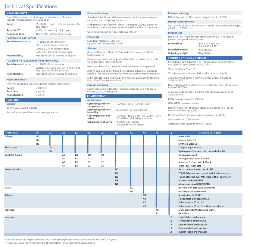
(1) Monitoring sensor parameters
Specific parameters of core indicators for sensor types
Composite gas sensor measurement range 25-2000 ppm (volume/volume H ₂ equivalent)
Accuracy ± 10% Reading ± 25 ppm
Response time of 10 minutes (90% of step change)
Relative sensitivity H ₂: 100% concentration; CO: 15 ± 4% concentration; C ₂ H ₄: 1.5 ± 0.5% concentration
Repeatability ± 5% reading or ± 5 ppm (whichever is greater)
Single H ₂ sensor (mineral oil only) relative sensitivity H ₂: 100% concentration; Affected by CO, C ₂ H ₂, C ₂ H ₄ interference
Repeatability ± 5% reading or ± 10 ppm (whichever is greater); Concentration error<3%
Moisture sensor (thin film capacitive) measuring range 0-100% RH
Accuracy ± 2% RH
Repeatability ± 2% RH
(2) Environmental and physical parameters
Category specific parameters
Working environment temperature -40 ° C~+55 ° C (-40 ° F~+131 ° F)
Working environment humidity 0-95% RH (non condensing)
Oil temperature at valve -40 ° C~+105 ° C (-40 ° F~+221 ° F) (optional fin heat dissipation adapter)
The oil pressure at the valve is 0-700KPa (0-100psi), and the sensor is resistant to vacuum
Protection level NEMA Type 4X, compliant with IP56 requirements
Power requirements: 90-132 Vac or 180-264 Vac switch mode universal power supply, 47-63 Hz, maximum 650VA
Functional characteristics
Alarm function:
Alarm types: gas/moisture warning (Hi), gas/moisture alarm (HiHi), system alarm
Alarm triggering: Gas alarm can be based on concentration, hourly/daily trend (rate of change); Moisture alarm can be based on concentration and average concentration; Support optional simulation input or model calculation result alarm
Data management: compatible with GE Perception ™ Software that supports data download and trend analysis
Insulation monitoring: Built in moisture sensor to monitor moisture in oil, identify paper aging and gasket leakage
Application scenarios
Applicable objects: Transformers in the power industry and industrial sector
Integrated configuration: Can be integrated with Kelman multi gas DGA equipment and Multilin 845 protection and control relays to achieve synchronization of chemical and electrical measurements
Core Value: Providing key data for Asset Performance Management (APM), assisting in maintenance plan development, and avoiding catastrophic transformer failures
key issue
Question 1: What is the core monitoring capability of Hydran M2-X? What types of transformer insulation oil are supported?
Answer: The core monitoring capability is to continuously monitor the gases (composite gases: H ₂, CO, C ₂ H ₄) in the insulation oil of transformers; Or single H ₂ and moisture content, with a gas measurement range of 25-2000 ppm (H ₂ equivalent) and a moisture measurement range of 0-100% RH; supported insulation oil types include mineral insulation oil, natural ester insulation oil, and synthetic ester insulation oil (single H ₂ sensor only supports mineral oil).
Question 2: What are the advantages of Hydran M2-X in communication and integration? Which systems/software are compatible?
Answer: Communication advantages include support for multiple interfaces (RS-232, RS-485, optional Ethernet/fiber) and protocols (standard Modbus) ®、 DNP 3.0; Optional IEC 61850, capable of local configuration and remote communication; In terms of integration compatibility, it can be compatible with the GE digital platform (Perception) ™ Transformer Fleet Management Software PREDIX ™、 The DS Agile substation HMI, SCADA system, historians, and APM software tools seamlessly integrate, and can also synchronize data with Kelman multi gas DGA equipment and Multilin 845 protection control relays.
Question 3: In what aspects is the reliability and maintenance convenience of Hydran M2-X reflected? What are the relevant key indicators?
Answer: Reliability is reflected in 40 years of on-site verification, global sales of over 50000 units, 7-year product warranty, sensor lifespan of over 10 years (MTTF 11.5 years), and protection level of IP56, suitable for wide temperature working environments ranging from -40 ° C to+55 ° C; The convenience of maintenance is reflected in the design of no moving parts, low maintenance requirements, on-site upgradability and expansion. During installation, existing transformer valves can be utilized (usually without shutdown), equipped with intuitive LCD display screens and keyboards, supporting local operation and manual sampling, reducing maintenance costs and downtime.
FBM224 is a product specifically designed for Foxboro Evo ™ Process Automation System and I/A Series ® The core function of the Modbus master communication interface module in system design is to build a communication bridge between Modbus slave devices (such as PLCs, field I/O devices, and smart meters) and system control processors (FCP280, FCP270/ZCP270, CP60), achieving seamless integration of device data from different vendors with the Foxboro system control database.
2. Core values
Multi protocol and multi interface compatibility: Supports RS-232, RS-422, and RS-485 communication interface standards simultaneously, adapting to the communication needs of the vast majority of Modbus slave devices without the need for additional converters;
Flexible redundancy deployment: supports port redundancy configuration (1&2 ports, 3&4 ports can be combined into logical redundancy ports), adapts to dual port Modbus devices, and improves communication link reliability;
Large capacity data exchange: A single module can connect to 64 Modbus slave devices, support 2000 DCI data connections, and can cover up to 32000 digital I/O points, meeting the data transmission needs of medium to large industrial scenarios;
Adaptation to hazardous environments: With the use of specialized terminal components (TA), it can be installed in Class I, Division 2, and Zone 2 hazardous areas, suitable for high-risk industries such as petrochemicals and natural gas;
Plug and play and easy maintenance: supports hot swappable design, module replacement does not require disconnecting on-site wiring, power and communication cables, reducing the risk of system shutdown.
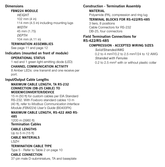
Hardware composition and physical characteristics
(1) Core hardware structure
1. Module body
Shell material: Made of sturdy extruded aluminum alloy shell, it has both physical protection and electrical shielding functions, and can resist vibration, impact, and electromagnetic interference in industrial sites;
Size specifications: Height 102mm (including installation ears 114mm) x Width 45mm x Depth 104mm, Weight approximately 284g (10oz), in compliance with the Compact 200 Series module standard size, suitable for modular base plate installation;
Status indicator lights: The front integrates 10 LED indicator lights, including 1 red (fault) and 1 green (running) status light, as well as 8 amber communication lights (1 transmitter light and 1 receiver light per port), providing real-time feedback on the module’s operating status and port communication activity.
2. Terminal Component (TA)
As the wiring hub between modules and field devices, TA has the following core designs:
Installation method: Supports 32mm or 35mm DIN rail installation, suitable for industrial standard installation scenarios;
Wiring interface:
RS-232: 4 standard DB-25 male connectors, each port is equipped with 24 DIP switches, and RS-232 signal pins can be flexibly configured (such as Clear to Send and Request to Send interconnection);
RS-422/RS-485: Three layer compression or ring terminal block, supporting 0.2-4mm ² solid/multi strand wires (24-12 AWG), suitable for on-site wiring of different wire diameters;
Key function: Built in switchable terminal resistors for each port (used for RS-422/RS-485 bus matching), reducing signal reflection interference; The material is polyamide (PA), which combines temperature resistance and mechanical strength;
Size and weight: Compressed TA length 216mm, weight 320g; Circular wiring TA length 250mm, weight 454g, can be selected according to on-site wiring requirements.
3. Connect the cable
Terminal cable: used for the connection between TA and modular base plate, using 37 pin D-subminiature male head, made of low smoke and halogen-free (LSZH) material, supporting four lengths of 1.0m, 2.0m, 3.0m, 5.0m (corresponding to models RH928AW/AZ, etc.), with a maximum extension of 5m (16 feet), suitable for different installation distance requirements;
On site communication cable:
RS-232: Following EIA standards, custom cables can be up to 15m (50 feet) long, while Foxboro standard cables can be up to 13m (40 feet) long;
RS-422/RS-485: Using shielded twisted pair cables, the longest communication distance can reach 1200m (3960 feet), meeting the requirements of long-distance distributed deployment.
(2) Installation and deployment features
1. Bottom plate installation
The module needs to be installed on the Foxboro modular base plate, which supports 4-slot or 8-slot FBM installation. It can be installed horizontally/vertically on DIN rails or on a 19 inch rack (with accompanying installation kit); The bottom board integrates FBM signal connectors, redundant 24V DC power interfaces, and I/O cable interfaces to ensure stable power supply and signal transmission of the module.
2. Hot swappable design
Modules can be directly plugged and replaced without the need to disassemble on-site equipment wiring, power cables, or communication cables, significantly reducing maintenance downtime and improving system availability.
Communication function and protocol support
1. Modbus protocol adaptation
Working mode: only supports Modbus RTU mode (asynchronous communication), does not support ASCII mode;
Function code support: Covering commonly used core industrial function codes to meet all data reading and writing requirements, as follows:
Function code function description application scenario
01 Read coil status, read digital output status (such as valve switch, indicator light status)
02 Read input status Read digital input status (such as sensor trigger signals, equipment fault feedback)
03 Read and hold registers to read device configuration parameters, cumulative data, etc. (such as cumulative flow rate of flow meters)
04 Read input register to read real-time measurement data (such as analog conversion values of temperature, pressure, and flow)
05 Mandatory single coil control for single digital output (such as starting/stopping motors, opening/closing valves)
06 Preset single register configuration device for individual parameters (such as setting pressure threshold, flow upper limit)
Self check the communication link between the 08 circuit diagnostic testing module and the slave device to troubleshoot connection faults
15. Mandatory batch control of multiple digital outputs with multiple coils (such as simultaneously starting a group of devices)
16 preset multi register batch configuration of device parameters (such as batch setting of measurement ranges for multiple instruments)
Data format: Supports 8-bit characters, configurable parity check (odd check/even check/no check), configurable stop bit (1 bit/2 bits), adaptable to communication parameter settings of different slave devices.
2. Port configuration and communication capability
(1) Port characteristics
The module is equipped with four independent serial communication ports, each of which can be individually configured as an RS-232, RS-422, or RS-485 interface without the need for hardware modification. Switching can be completed through software configurator;
Port redundancy function: Ports 1&2 and 3&4 can be configured as a single logical port, and can be connected to dual port Modbus devices with redundant cables to achieve communication link redundancy and avoid data interruption caused by single point failures.
(2) Communication parameters
Transmission rate: Supports 10 speeds including 300, 600, 1200, 2400, 4800, 9600, 19200, 38400, 57600, and 115200 baud, and can be flexibly selected according to communication distance and device requirements (low-speed is recommended for long-distance communication, high-speed is recommended for short distance high-speed transmission);
From device address: Supports a range of 1-247 addresses, which can cover the addressing requirements of Modbus devices in the vast majority of industrial scenarios.
3. Data interaction capability
(1) Access capacity
A single module can support up to 64 Modbus slave devices (the actual number is affected by device type, data volume, and scanning rate);
A single module can support up to 2000 distributed control interface (DCI) data connections, covering:
2000 analog I/O values (integer or IEEE single precision floating-point type);
32000 digital I/O values (calculated by packing 32 digital points per connection);
Mixed analog and digital data connection.
(2) Data processing and updating
As a Modbus master, the module periodically polls the input data from the device according to the user configured scanning rate, and the output request is immediately executed after being sent by the control processor, without being limited by the polling cycle;
The access speed of the control station to FBM224 data can reach up to 500ms at the fastest, with low data update latency, meeting real-time control requirements;
Support data format conversion: The module automatically converts raw data from the device (2-byte/4-byte signed/unsigned integers, 4-byte IEEE floating point types, binary values) into Foxboro system compatible format and stores it in the system database for use by plant management functions and operator interfaces; Simultaneously supporting byte order and bit order switching, adapting to data storage formats of devices from different manufacturers.
Configuration tools and operating procedures
1. Configuration tool
Provide Windows ® Compared to Solaris ® There are two versions of configurator for operating systems, namely port configurator and device transaction configurator. During the configuration process, the validity of parameters (such as rate range and address legality) is automatically verified to avoid configuration errors.
(1) Port configurator
Used to set communication parameters for each port, including:
Communication interface standard (RS-232/RS-422/RS-485);
Transmission rate, parity check, stop bit;
Enable/disable port redundancy mode (1&2 ports, 3&4 ports).
(2) Device Transaction Configurator
Used to set communication transaction parameters for slave devices, including:
Scanning rate: configurable from 0.5 seconds to 255 seconds, default 500ms, adjustable according to device response speed and real-time data requirements;
Phase setting: When the scanning rate is an integer multiple of the base period, specify the specific scanning period to distribute the communication load between the module and the device;
Transaction details: Function code, starting address of data, amount of data transmitted in a single transaction, up to 64 independent transaction configurations supported by a single device.
2. Control block support
The module is compatible with Foxboro standard DCI control block types, through Foxboro Evo Control Editors、I/A Series Configuration Component(IACC)、Integrated Control Configurator(ICC) Or FoxCAE ™ The software is configured in the control processor, and the control block interacts with Modbus slave devices for data read and write through address mapping. The supported types of control blocks are as follows:
Function description of control block type
BIN binary input
BINR redundant binary input
BOUT binary output
IIN integer input
IOUT integer output
PAKIN packaging input (multi digit point packaging)
PAKOUT packaging output (multi digit point packaging)
PLSOUT pulse output
RIN Real Input (Floating Point Type)
RINR redundant real number input
ROUT Real Output (Floating Point Type)
Core performance parameters and environmental adaptability
1. Electrical performance
Power requirements: Redundant 24V DC power supply, voltage range+5%~-10% (i.e. 21.6V~25.2V DC), maximum power consumption 7W, maximum heat dissipation 7W, compatible with Foxboro standard redundant power supply (such as FPS480-24);
Channel isolation: Galvanic isolation is used between each communication channel and ground, which can withstand 600V AC voltage for 1 minute without damage, effectively avoiding ground loop interference and high voltage intrusion;
Fieldbus communication: Communicate with FCM (fieldbus communication module) or control processor through redundant 2Mbps module fieldbus, support A/B dual path switching, automatically switch to another path when one path fails, ensuring communication continuity.
Relative humidity: 5%~95% (non condensing), suitable for industrial environments with high humidity and large temperature differences.
(2) Anti interference and protection
Electromagnetic Compatibility (EMC): Complies with the European EMC Directive 2004/108/EC, EN61326:2013 Class A emission standards and industrial immunity levels, including:
Electrostatic discharge (ESD): Contact 4kV, air 8kV;
Radiated field immunity: 10V/m at frequencies of 80-1000MHz;
Electric fast transient/pulse group: I/O, DC power supply and communication line 2kV;
Surge immunity: ± 2kV for AC/DC power lines, ± 1kV for I/O and communication lines;
Pollution level: Compliant with ISA S71.04 Class G3 (harsh environment) standard, resistant to industrial dust, oil pollution and other pollution;
Vibration and impact: Can withstand vibrations of 7.5m/S ² (0.75g) and 5-500Hz, suitable for the vibration environment generated by industrial field equipment operation.
Security certification and compliance
The module is certified through multiple regions and standards to ensure compliant use in different countries/regions and hazardous environments
Specific standards and instructions for certification types
Electrical Safety (US Canada) UL/UL-C certification, applicable to Class I, Groups A-D; Division 2; T4 temperature group shell system; As an associated device, provide non flammable communication circuits for Class I, Groups A-D hazardous areas; Meets the Class 2 circuit requirements of the National Electrical Code (NFPA 70 Article 725) and the Canadian Electrical Code (CSA C22.1 Section 16)
European certification for Low Voltage Directive 2006/95/EC and Explosion proof Directive 94/9/EC; DEMKO certification for EEx nA IIC T4, suitable for Zone 2 hazardous areas, as an associated device providing non flammable on-site circuits for Zone 2, Group IIC potentially explosive environments
Environmental compliant terminal components (TA) and terminal cables comply with the EU RoHS Directive 2002/95/EC and revised 2011/65/EU, restricting the use of harmful substances such as lead and mercury
Electromagnetic compatibility complies with CISPR 11 Industrial, Scientific, and Medical (ISM) Radio Frequency Equipment Electromagnetic Disturbance Limits, IEC 61000 series immunity standards (static electricity, radiation, surge, etc.)
Typical application scenarios and topology configuration
1. Applicable industries and scenarios
Core industries: petrochemical, natural gas, power, water treatment, manufacturing (such as automobiles, electronics) and other industrial fields that require multi device interconnection;
Typical applications:
Data exchange between PLCs from different manufacturers and Foxboro systems (such as connecting equipment status data from third-party PLCs to the Foxboro operator interface);
Intelligent instruments (such as flow meters, pressure transmitters) data acquisition (reading instrument measurement values through Modbus RTU);
Distributed I/O device control (controlling the output ports of remote I/O modules through Modbus commands);
Communication of hazardous area equipment (such as safety communication between sensors and systems in Zone 2 of the petrochemical industry).
2. Typical topology configuration
The module supports multiple Modbus network topologies and adapts to different on-site layout requirements. The core configuration is as follows:
(1) Redundant link configuration
Topology: Ports 1 and 2 are configured as redundant logical ports, while ports 3 and 4 are configured as redundant logical ports. They are respectively connected to dual port Modbus slave devices or to redundant links of single port devices through redundant cables;
Advantages: Avoiding data interruption caused by a single communication link failure, improving system reliability, and suitable for critical control circuits.
(2) Mixed interface configuration
Topology structure: Four ports are configured as different interfaces (such as one port for RS-232 connection to a modem, two ports for RS-422 direct connection to devices, and three&four ports for RS-485 multi-point bus connection to multiple instruments);
Advantages: Devices that can adapt to multiple communication interfaces simultaneously, without the need for additional interface converters, reducing system complexity.
(3) Remote distributed configuration
Topology structure: Multiple slave devices (such as flow meters and pressure sensors deployed along pipelines) are connected on a single bus through the 1200m long-distance transmission capability of RS-485 interface. The modules are deployed in the control room and the on-site devices are installed in a distributed manner;
Advantages: Reduce on-site wiring costs, simplify construction difficulties, and adapt to large-scale industrial scenarios.
Key selection and deployment considerations
1. Key selection points
Confirm the communication interface (RS-232/RS-422/RS-485) and Modbus mode (RTU mode required) of the device;
Determine whether the module capacity meets the requirements based on the number of devices (≤ 64) and data points (≤ 2000 DCI connections);
In hazardous environments, it is necessary to confirm the installation area level (Class I, Division 2 or Zone 2) to ensure that the module matches the certification of the TA;
When the communication distance exceeds 15m (RS-232) or requires multi-point connection, RS-485 interface is preferred.
2. Deployment precautions
Wiring specification: RS-422/RS-485 requires shielded twisted pair cables, and terminal resistors (configured through TA’s DIP switch) should be enabled at both ends of the bus to avoid signal reflection; RS-232 wiring needs to match the device pin definition (adjusted through TA’s DIP switch);
Power configuration: It is recommended to use redundant power supply in key scenarios to avoid module shutdown caused by power failure;
Electromagnetic interference protection: Modules and cables should be kept away from strong electromagnetic interference sources such as frequency converters and motors, and the shielding layer should be grounded at one end to reduce interference effects;
Software compatibility: Ensure that the control system software version meets the requirements (I/A Series v8.8+or Foxboro Evo v9.0+) to avoid incompatibility between configuration tools and the system.
The Compact 200 Series I/O subsystem is a distributed control electronic device designed for industrial sites. Its core design goal is to reduce on-site wiring costs and improve system flexibility through distributed deployment, while maintaining compatibility with Foxboro legacy systems, meeting the modern industrial demand for high reliability and high-precision control.
2. Core values
Cost optimization: Distributed deployment significantly reduces the procurement and installation costs of on-site cables, cable trays, and conduits, and lowers the initial project investment;
Strong compatibility: compatible with existing I/A Series ® The system’s 200 Series I/O devices and outdated 100 Series I/O devices are fully compatible, supporting seamless upgrades of existing systems and protecting users’ existing investments;
Flexible deployment: With the help of Fast Ethernet network, device domain communication can be achieved, and I/O points can be flexibly selected for local centralized deployment or remote distributed deployment according to the factory layout;
Environmental adaptation: With the ability to adapt to harsh environments, it can operate stably in complex scenarios such as pollution, high temperatures, and potential explosions.
Hardware composition system
(1) Control processor module
As the “brain” of the subsystem, the control processor is responsible for connecting the fieldbus module (FBM) with the control network, implementing control logic operations and data transmission. It is divided into three core models:
Model Form and Adaptation Scenario Core Functions
FCP280 (Field Control Processor 280) compact module provides control interface between FBM and control network, supports up to 4 HDLC fieldbus, and can connect 128 200 Series FBMs or 100/200 Series hybrid FBMs (up to 64 for 100 Series); Supports dual baud rate function and can work together with FBI200 to adapt to 100/200 Series FBM
FCP270 (Field Control Processor 270) compact module has similar functionality to FCP280, supporting up to 32 200 Series FBMs (without FEM100) or 128 (with FEM100), and up to 64 100 Series FBMs; Need to be paired with FBI100 to achieve dual baud rate communication with 100 Series FBM
ZCP270 (Z-Module Control Processor 270) Z-module form adaptation for 100 Series FBM rack, supporting control operations for 100/200 Series FBM; Through FCM100E/Et expansion, a single ZCP270 can connect up to 128 100/200 Series FBMs
(2) Fieldbus Module (FBM): Core Function Carrier
FBM is the core I/O module of the subsystem, responsible for collecting on-site sensor signals and executing control command outputs. It has high integration and reliability characteristics and can be divided into the following categories according to its functions, covering various signal requirements in industrial sites:
1. Core features of the module
Full coverage of signal types: Supports 0-20mA/4-20mA current signal, 0-10V voltage signal, thermocouple, RTD (platinum/nickel/copper material) HART ® Communication, discrete (digital) input/output, pulse signals, etc;
Isolation level classification:
Channel isolation: Each channel is completely galvanic isolated from other channels, grounding, and module logic, suitable for scenarios with high precision and anti-interference requirements;
Differential isolation: There is no isolation between channels, but they are isolated from grounding and module logic, supporting voltage differences between channels without additional error compensation;
Group isolation: Input channels are isolated from grounding and module logic as a group, and some models can achieve channel level isolation through terminal components (TA);
Redundancy support: Some models support redundant configurations (such as FBM216b, FBM218, FBM248), which need to be installed in pairs and paired with redundant adapters; Some models are “redundancy ready” (such as FBM207b, FBM237), which can flexibly switch between single module/dual module redundancy modes.
2. Key model function details
Module Series Core Model Function Description Typical Applications
Analog input (AI) FBM201 8-channel 0-20mA input, isolated channel for ordinary current signal acquisition (such as pressure and flow sensors)
FBM202 8-channel thermocouple/millivolt input, channel isolation temperature measurement (thermocouple signal)
Discrete Input (DI) FBM207/b/c 16 channel DC voltage monitoring/contact detection (24V/48V), redundant ready switch status, contact signal acquisition
FBM217 32 channel discrete input, group isolated high-density digital signal acquisition (such as equipment operation status)
Discrete I/O (DI/DO) FBM219 24 channel DI+8 channel DO, external power supply, group isolation mixed discrete data acquisition and control (such as valve switch+status feedback)
FBM241/c/d 8-channel voltage monitoring/contact detection+8-channel DO, channel isolation high-precision discrete mixed control scenario
Multi functional I/O FBM247/248 8-channel current/voltage/analog/digital/pulse configurable I/O, supporting HART ®, FBM248 supports redundant complex mixed signal scenarios (such as pulse counting+analog acquisition+digital output)
(3) Auxiliary function module
1. Fieldbus isolator/filter (FBI200)
Core function: Expand the fieldbus distance between FCP and FBM modules, with dual axis cable transmission up to 305 meters (1000 feet);
Adaptation features: When paired with FCP270, it can filter 2Mbps (200 Series) and 268Kbps (100 Series) signals to avoid mutual interference; When used in conjunction with FCP280, it is only used to extend communication distance and does not require filtering isolation.
2. Fieldbus Communication Module (FCM Series)
Responsible for signal conversion and long-distance communication expansion, supporting redundant configuration. The model details are as follows:
Model Core Function Communication Distance Adaptation Scenario
FCM100Et 100Mbps fiber optic signal → 2Mbps electrical signal (for 200 Series FBM) – Short distance extension of fiber optic to electrical signal, requiring paired redundant deployment
FCM100E 100Mbps fiber optic signal → 2Mbps (200 Series) or 268Kbps (100 Series) electrical signal – needs to adapt to mixed scenarios of 100/200 Series FBM simultaneously
FCM2F2/2F4/2F10 module fieldbus fiber optic expansion, divided into 3 models 2km/4km/10km (paired deployment) for long-distance communication between baseboards, with two FCM2F10s connected in series up to 20km
Installation method: Supports horizontal DIN rail installation (standard/non isolated) or 19 inch rack installation (requires installation board);
Key features:
Provide communication backplane and module installation foundation, supporting deployment of 16 Compact FBMs;
Volume optimization: 1 compact base plate+16 compact FBMs occupying approximately 2 standard 200 Series base plates+16 standard FBMs;
Scalability: Supports backplane chain expansion (up to 32 FBMs), allowing for online addition of new baseboards without the need for downtime;
Power and Communication: Provides main/backup 24V DC power interface, dual module fieldbus (A/B) daisy chain interface, supports DIP switch address recognition.
2. Enclosures
Provide environmental protection and equipment integration, divided into G/K series, adapted to different scene requirements:
Series Core Model Protection Level Adaptation Scenarios
G series G13 (system shell), G14 (system+terminal shell), G11 (terminal shell) IP43/54 normal environment, supporting installation of FBM, FCM, FCP and terminal components
The K series K13 (system casing), K14 (system+terminal casing), K11 (terminal casing) have the same IP43/54 functionality as the G series, providing differentiated selection
Common features – built-in DIN rail, power supply interface, terminal block; Support single/redundant power supply deployment; Certified by UL, ATEX, etc., suitable for ordinary and potentially explosive environments
Core technical characteristics and performance parameters
1. High performance and high precision
Analog acquisition: SigmaDelta fast integration ADC is used, with an analog input update rate of up to 25ms, suitable for high-speed regulation and control;
Anti interference capability: Built in configurable moving average filter, effectively suppressing process electromagnetic noise;
Measurement accuracy: Depending on the specific FBM model, the channel isolation module has higher accuracy and error control within the allowable range of industrial grade (such as RTD module supporting 0-320 Ω range, error ≤± 0.1%).
2. High reliability and availability
Component integration: Integrating logic functions such as I/O processing and communication processors through ASIC (Application Specific Integrated Circuit) to reduce the number of module components and lower the probability of failure;
Availability indicators:
Single module (with redundant power supply, MTTR=2 hours): availability ≈ 0.999974;
Redundancy support: Full link redundancy options, including power supply, control network FCM、 Control processor, fieldbus cables, and some FBMs, with no single point of failure risk.
3. Environmental adaptability
Working temperature: The maximum working temperature of Compact FBM is 60 ℃ (140 ° F);
Pollution protection: Class G3 (ISA S71.04) pollution level, resistant to industrial dust, oil pollution and other environments;
Certification compliance: UL (US/Canada), ATEX (DEMKO), CE, RoHS certification, suitable for ordinary areas and potentially explosive environments (Ex certification).
4. Deployment and maintenance convenience
Hot swappable design: FBM modules can be directly plugged and unplugged without disconnecting external field equipment wiring or internal cables;
Online expansion: Supports adding new baseboards to the baseboard chain online, without the need for downtime in redundant HDLC fieldbus environments;
Fault diagnosis: Power supply faults can be indicated through three prompts: SMDH (System Management Interface) icon color change, system monitoring display, and alarm printing; FBM faults can be quickly located by controlling network feedback.
Compatibility and upgrade requirements
1. Software compatibility
Required software version: I/A Series software v8.8 or Foxboro Evo Control Core Services v9.0 or above;
Supporting tools: Corresponding versions of system configuration software (such as SMDH) are required for module configuration, fault monitoring, and maintenance.
2. Hardware compatibility
Control processor: Only supports FCP280, FCP270, and ZCP270, and requires corresponding sizing guidelines (such as FCP280 reference B0700FY) to confirm capacity;
Power supply: Supports four types of 24V DC power supplies: FPS480-24, FPS400-24, FPS240-24, and FPS120-24. The selection should be based on the enclosure power budget;
Terminal Component (TA): Different FBMs require dedicated TAs (such as TAs with relays for high voltage/high current digital outputs), and some TAs provide additional channel isolation functionality.
3. Upgrading Path for Existing Systems
The existing standard 200 Series subsystem can be directly upgraded to Compact 200 Series, with the following steps:
Remove the standard 200 Series horizontal bottom plate and replace it with a Compact 200 Series 16 slot bottom plate;
Confirm installation environment: Ensure sufficient horizontal DIN rails, power capacity, and heat dissipation space (1 fan tray is required for every 2 adjacent Compact baseboards, and 1 tray is required for every 1 baseboard when deployed separately);
Replace cable: Replace the terminal cable of the standard FBM with the dedicated cable corresponding to the Compact FBM (refer to the PSS document of each FBM);
Software adaptation: Upgrade to a compatible version of I/A Series or Foxboro Evo software to complete module configuration.
Application scenarios and industry adaptation
1. Core application scenarios
Continuous process control: continuous production processes in industries such as petrochemicals, chemical engineering, and power (such as reactor temperature/pressure control, pipeline flow regulation);
Batch production control: Batch production processes in industries such as pharmaceuticals, food and beverage (such as ingredient ratio control, batch data collection);
Discrete control: Discrete equipment control in manufacturing industry (such as valve switching, motor start stop, status monitoring);
Existing system upgrade: Performance upgrade and expansion needs of existing Foxboro 100/200 Series system users.
2. Scope of environmental adaptation
Ordinary industrial environment: factory workshop, control room, compatible with IP43/54 protection level;
Adverse environment: Class G3 pollution level, high temperature (60 ℃) environment, such as metallurgical plants and chemical plant sites;
Hazardous environment: Potential explosive atmosphere (ATEX certified), such as explosion-proof areas in the petrochemical industry.